Sign In
Upload
Manuals
Brands
Daikin Manuals
Accessories
DWSC - Vintage C
Daikin DWSC - Vintage C Manuals
Manuals and User Guides for Daikin DWSC - Vintage C. We have
2
Daikin DWSC - Vintage C manuals available for free PDF download: Installation, Operation And Maintenance Manual, Operating Manual
Daikin DWSC - Vintage C Installation, Operation And Maintenance Manual (57 pages)
Brand:
Daikin
| Category:
Accessories
| Size: 2 MB
Table of Contents
Table of Contents
2
Fig. 1 - Typical Oil Circuit
6
Fig. 2 - Description of the Labels Applied to the Electrical Panel
8
Fig. 3 - - Description of the Labels Applied to the Motor Terminal Box
8
Fig. 4 - Label on Compressor
9
1 Introduction
10
Precautions against Residual Risks
11
Description
12
2 Receiving the Unit
13
Fig. 5 - DWSC Major Component Locations
13
3 Operating Limits
14
Storing Storage
14
Operation
14
4 Mechanical Installation
15
Safety
15
Positioning and Assembly
15
System Water Volume
15
Condensation Control with Evaporative Cooling Tower
15
Condensation Control with Well Water
16
Fig. 6 - Condeser Control Scheme with Cooling Tower
16
Fig. 7 - Condensation Control Scheme with Well Water
16
Water Piping
17
Water Pumps
17
Vessel Drains at Start-Up
17
Evaporator and Condenser Water Piping
17
Important Note on Welding
17
Flow Switch
17
Fig. 8 - Flow Switch Mounting
17
Cooling Towers
18
Water Treatment
18
Table 1 - Flow Switch Rates
18
Table 2 - Acceptable Water Quality Limits
18
Field Insulation Guide
19
Physical Data and Weights
21
Evaporator
21
Condenser
21
Pumpdown
21
Table 3 - Evaporator Data
21
Table 4 - Condenser Data
21
Compressor
22
Oil Coolers
22
Table 5 - Compressor Weights
22
Table 6 - DWSC, Oil Cooler Data
22
Fig. 9 - Oil Cooler Piping Across Chilled Water Pump
23
Fig. 10 - Oil Cooler Piping with City Water
23
Fig. 11 - DWSC, Oil Cooling Connections
23
Table 7 - Cooling Water Connection Sizes
23
Oil Heater
24
Relief Valves
24
Refrigerant Vent Piping
24
Fig. 12 - Condenser 3-Way Valve
24
5 Electrical Installation
25
General Specifications
25
Electrical Supply
25
Power Wiring
25
Control Power Wiring
26
Flow Switches
26
Control Panel Switches
26
Cable Requirements
26
Table 8 - Table 1 of EN60204-1 Point 5.2
26
Phase Unbalance
27
6 Prestart System Checklist
28
7 Operation
29
Operator's Responsibilities
29
Standby Power
29
Lubrication System
29
Table 9 - Approved Polyolester Oils for R134A Units
29
Hot Gas Bypass
30
Condenser Water Temperature
30
8 Maintenance
31
Pressure/Temperature Chart
31
Routine Maintenance
32
Lubrication
32
Changing Oil Filters
34
Refrigerant Cycle
34
Electrical System
34
Table 10 - Upper Limit for Wear Metals and Moisture in Polyolester Oils in Daikin Centrifugal Chillers
34
Compressor Maintenance
35
Flanged Joints Disassembly
35
Cleaning and Preserving
36
Annual Shutdown
36
Annual Startup
36
Repair of System
36
Pressure Relief Valve Replacement
36
Pumping down
36
Pressure Testing
37
Leak Testing
37
Evacuation
37
Charging the System
37
9 Maintenance Schedule
38
10 Service Programs and Warranty Statement
40
11 Periodic Checks and Commissioning of Pressure Equipment
40
12 Disposal
40
13 Important Information Regarding the Refrigerant Used
41
Factory and Field Charged Units Instructions
41
14 Annex A: Variable Frequency Drive
42
Acceptance of the Product
42
Checks
42
Abbreviations
42
VFD Nomenclature for C Series
42
Vfds and Distortion
43
VFD Line Harmonics
43
Current Harmonics
43
Voltage Harmonics
43
EMI and RFI Filter
43
Safety
44
Avoid Electrocution
44
Fig. 13 - Label: Risk of Electric Shock
44
Residual Risks
45
Handling and Transport
45
Mechanical Installation
46
Shipping
46
Cabinet Handling and Lifting
46
Fig. 14 - Angle to Respect for Lifting Operation
46
Positioning and Assembly
47
Minimum Space Requirements
47
Fig. 15 - Lifting the VFD
47
Fig. 16 - Minimum Space Requirements for VFD
47
General Specifications
48
Product Identification
48
Fig. 17 - VFD Identification Label
48
Fig. 18 - Electrical Panel (Mono) Identification Label
48
Fig. 19 - Electrical Panel (Dual) Identification Label
48
Individuation of Parts
49
Fig. 20 - Inverter Panel Parts (Mono)
49
Fig. 21 - Inverter Panel Parts (Dual)
49
Specification
50
Fig. 22 - VFD Replaceable Parts Highlighted
50
Directives and Standards
51
VFD Terminals
52
Piping Connections
52
Fig. 23 - P&ID Diagram of the Unit with Inverter Cooling Line Detail
52
Maintenance
53
Ordinary Maintenance
53
Extraordinary Maintenance
54
Vfd Communication
54
Modbus RTU Configuration
54
Modbus Parameters
55
Advertisement
Daikin DWSC - Vintage C Operating Manual (39 pages)
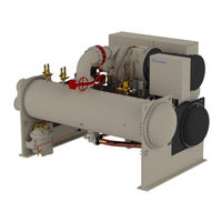
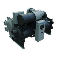
WATER COOLED CENTRIFUGAL CHILLERS
Brand:
Daikin
| Category:
Accessories For Chillers & Freezers
| Size: 2 MB
Table of Contents
Table of Contents
2
Safety Considerations
4
General
4
Before Switching the Unit
4
Avoid Electrocution
4
General Description
5
Basic Information
5
Abbreviations Used
5
Controller Operating Limits
5
Controller Architecture
5
Communication Modules
6
LIST of FIGURES Figure 1 - Controller Architecture
6
Using the Controller
7
Figure 2 - Microtech POL688.80 Controller
7
Figure 3 - Using the Controller
7
Figure 4 - Inbuilt HMI
7
Navigating
8
Passwords
8
Editing
9
Basic Control System Diagnostic
9
Controller Maintenance
10
Optional Remote User Interface
10
Embedded Web Interface
11
Menu Structure
12
Main Menu
12
View/Set Unit
12
Thermostat Ctrl
13
Network Ctrl
13
Pumps
13
Condenser
13
Evaporator
14
Master/Slave
14
Data
14
Options
15
Thermostat Ctrl
15
Timers
15
Standby Chiller
16
Rapid Restart
16
Date/Time
16
Scheduler
16
Power Conservation
17
Demand Limit
17
Current Limit
17
Softload
17
Setpoint Reset
17
Controller IP Setup
17
Daikin on Site
18
Software Options
18
Changing the Password for Buying New Software Options
18
Inserting the Password in a Spare Controller
19
Modbus MSTP Software Option
20
Bacnet Mstp
21
Bacnet Ip
22
Menu Password
23
Active Setpoint
23
Evaporator LWT
23
Condenser LWT
23
Unit Capacity
23
Unit Mode
24
Unit Enable
24
Timers
24
4.10 Alarms
24
4.11 Commission Unit
25
Alarm Limits
25
Calibrate Sensors
25
Unit Calibrate Sensors
25
Compressor Calibrate Sensors
26
Scheduled Maintenance
26
4.12 about this Chiller
26
Working with this Unit
27
Unit Setup
27
Control Source
27
Available Mode Setting
27
Temperature Settings
28
LWT Setpoint Setting
28
Thermostat Control Settings
28
Pumps
29
Power Conservation
29
Demand Limit
29
Figure 5 - Thermostat Control Settings
29
Current Limit
30
Setpoint Reset
30
Setpoint Reset by External 4-20 Ma Signal
30
Setpoint Reset by Evaporator Return Temperature
30
Soft Load
31
Scheduler
31
Unit Start-Up
31
Unit Status
31
Prepare the Unit to Start
32
Unit Switch Enable
32
Keypad Enable
32
BMS Enable
32
Condensation Control (Optional)
32
Figure 6 - Condenser Water Temperatur
33
Operator Interface Touchscreen-Oits
34
Overview
34
Set User Level
35
Homepage
35
Global Settings
36
Tab
37
Live Trend
37
Options
38
Energy Meter Including Current Limit (Optional)
38
Rapid Restart (Optional)
38
Advertisement
Related Products
Daikin DFC Series
Daikin DFG180
Daikin DFG240
Daikin DFG300
Daikin DFG Series
Daikin DFG090
Daikin DFG102
Daikin DFG120
Daikin DFG150
Daikin DP3G Series
Daikin Categories
Air Conditioner
Heat Pump
Remote Control
Chiller
Air Handlers
More Daikin Manuals
Login
Sign In
OR
Sign in with Facebook
Sign in with Google
Upload manual
Upload from disk
Upload from URL