Table of Contents
Advertisement
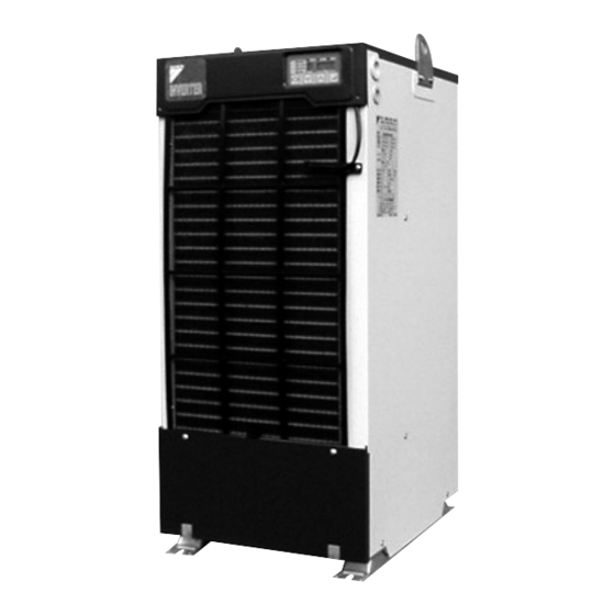
DAIKIN Oil Cooling Unit
("OILCON")
AKZ8 Series
Models
Menu
Built-in
Standard
breaker
model
model (-B)
Series
AKZ148
AKZ328
AKZ438
AKZ568
AKZ908
Thank you for purchasing DAIKIN Oil Cooling Unit ("OILCON").
This instruction manual includes instructions for using the Oil
Cooling Unit.
To ensure proper use of this product, be sure to read through this
instruction manual before using it.
After reading this manual, keep it handy for your future reference.
Proper use results in power saving
If the air filter is clogged, the cooling performance deteriorates,
causing excess power consumption.
Clean the air filter periodically to reduce power consumption.
Instruction Manual
Circulating type
Built-in heater
Built-in tank
model
model
Built-in breaker
model
CE model
Built-in
Different-
CE model
heater
voltage
(-C)
model (-H)
model (-E)
Installation
Handling
Different-voltage
model
(or Machine Temperature)
Built-in
tank model
(-T1, -T)
Devices (Installed by User)
Maintenance
• When the unit operation seems abnormal
although no alarm is activated
CONTENTS
1
4
5
6
7
12
14
15
16
18
19
20
21
22
23
24
25
27
30
33
33
34
35
36
37
38
Advertisement
Table of Contents


Need help?
Do you have a question about the AKZ8 Series and is the answer not in the manual?
Questions and answers