Table of Contents
Advertisement
Quick Links
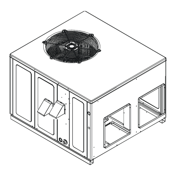
DP3G 13.4 SEER2 "M" SERIES
S
P
ingle
AckAge
O
NLY PERSONNEL THAT HAVE BEEN TRAINED TO INSTALL
(
, "
REPAIR
HEREINAFTER
SERVICE
MANUAL SHOULD SERVICE THE EQUIPMENT
BE RESPONSIBLE FOR ANY INJURY OR PROPERTY DAMAGE ARISING FROM
IMPROPER SERVICE OR SERVICE PROCEDURES
ASSUME RESPONSIBILITY FOR ANY INJURY OR PROPERTY DAMAGE WHICH MAY
. I
,
RESULT
N ADDITION
IN JURISDICTIONS THAT REQUIRE ONE OR MORE
LICENSES TO SERVICE THE EQUIPMENT SPECIFIED IN THIS MANUAL
LICENSED PERSONNEL SHOULD SERVICE THE EQUIPMENT
,
,
INSTALLATION
ADJUSTMENT
SERVICING OR REPAIR OF THE EQUIPMENT
,
SPECIFIED IN THIS MANUAL
OR ATTEMPTING TO INSTALL
REPAIR THE EQUIPMENT SPECIFIED IN THIS MANUAL WITHOUT PROPER
TRAINING MAY RESULT IN PRODUCT DAMAGE
.
INJURY OR DEATH
IOD-3024
06/2022
g
-e
AS
lectRic
,
ADJUST
")
THE EQUIPMENT SPECIFIED IN THIS
. T
HE MANUFACTURER WILL NOT
. I
F YOU SERVICE THIS UNIT
. I
MPROPER
,
ADJUST
,
PROPERTY DAMAGE
Our continuing commitment to quality products may mean a change in specifications without notice.
19001 Kermier Road, Waller, TX 77484
W
R-410A
ith
h
& c
eAting
ooling
Users Information Manual adjacent to the unit.
RECOGNIZE THIS SYMBOL AS A SAFETY PRECAUTION.
These installation instructions cover the outdoor installation
of self contained package air conditioners and heating units.
See the Specification Sheets applicable to your model for
information regarding accessories.
*NOTE: Please contact your distributor or our website for
the applicable Specification Sheets referred to in this manual.
This Forced Air Central Unit Design Complies With Require-
ments Embodied In The American National Standard / Na-
tional Standard of Canada Shown Below.
ANSI Z21.47•CSA-2.3 Central Furnaces.
,
SERVICE OR
DO NOT BYPASS SAFETY DEVICES
,
YOU
,
ONLY
,
SERVICE OR
,
PERSONAL
www.daikincomfort.com
1
INSTALLATION INSTRUCTIONS
U
nit
Affix this manual and
WARNING
Advertisement
Table of Contents

Related Manuals for Daikin DP3G Series


Summary of Contents for Daikin DP3G Series
- Page 1 INSTALLATION INSTRUCTIONS DP3G 13.4 SEER2 “M” SERIES R-410A & c ingle AckAge lectRic eAting ooling Affix this manual and Users Information Manual adjacent to the unit. RECOGNIZE THIS SYMBOL AS A SAFETY PRECAUTION. These installation instructions cover the outdoor installation of self contained package air conditioners and heating units.
-
Page 2: Table Of Contents
Index FLAME SENSOR (QUALIFIED SERVICER ONLY)..... 22 FLUE PASSAGES (QUALIFIED SERVICER ONLY) ....22 REPLACEMENT PARTS ..............3 CLEANING FLUE PASSAGES ORDERING PARTS ..............3 (QUALIFIED SERVICER ONLY) ........... 23 SAFETY INSTRUCTIONS..............3 MAIN BURNER FLAME (QUALIFIED SERVICER ONLY)..23 TO THE INSTALLER..............3 CLEANING BURNERS ............23 GENERAL INFORMATION ..............5 ACCESSORIES AND FUNCTIONAL PARTS ........23 TRANSPORTATION DAMAGE .......... -
Page 3: Replacement Parts
For the location of your nearest distributor, consult the white business pages, the yellow page section of the local telephone book or contact: HOMEOWNER SUPPORT DAIKIN NORTH AMERICA LLC 19001 KERMIER ROAD WALLER, TEXAS 77484 WARNING... - Page 4 CARBON MONOXIDE POISONING HAZARD RISQUE D’INTOXICATION AU MONOXYDE DE CARBONE Failure To Follow The Steps Outlined Below For Each Appliance Si les étapes décrites ci-dessous ne sont pas suivies pour chacun Connected To The Venting System Being Placed Into Operation des appareils raccordés au système de ventilation au moment Could Result In Carbon Monoxide Poisoning Or Death.
-
Page 5: General Information
Specification sheets can be found at www.daikincomfort.com 3. In case of concealed damage, carrier should be for Daikin brand products. Within the website, please select notified as soon as possible-preferably within 5 days. the residential or commercial products menu and then select 4. -
Page 6: Unit Location
Unit location should be a minimum of 48” clearance and provisions made to deflect the warm discharge air out from the WARNING overhang. • Close to the wall application assures free, unobstructed O PREVENT POSSIBLE E QUIPMENT D AMAGE, P ROPERTY DAMAGE, PERSONAL air to the other two sides. -
Page 7: Roof Curb Installations Only
• The unit may be installed directly on wood floors or on Refer to the Roof Curb Installation Instructions for proper curb Class A, Class B, or Class C roof covering material. installation. Curbing must be installed in compliance with the National Roofing Contractors Association Manual. -
Page 8: High Altitude Derate (U.s. Installations Only)
joint compound must be resistant to the action of the Inlet Gas Pressure Must be within the minimum and Maximum fuel used. Value Shown in Table Above. The minimum supply pressure should not vary from that 3. Use ground joint unions. shown in the table above because this could prevent the unit 4. -
Page 9: Gas Piping Checks
Gas Piping Checks Tanks and Piping Complete information regarding tank sizing for vaporization, CAUTION recommended regulator settings and pipe sizing is available from most regulator manufacturers and propane O PREVENT PROPERTY DAMAGE OR P ERSONAL INJURY D UE T O FIRE, THE gas suppliers. -
Page 10: Electrical Wiring
WARNING Thermostat O PREVENT PROPERTY D AMAGE OR S ERIOUS P ERSONAL INJURY D UE T O Two-Stage Heating FIRE O R EXPLOSION CAUSED B Y A PROPANE GAS LEAK, I NSTALL A GAS with DETECTING WARNING DEVICE. Two-Stage Cooling F THE PROPANE GAS UNIT I S INSTALLED IN A N EXCAVATED AREA OR A CONFINED S PACE, A WARNING DEVICE I S REQUIRED D UE T O: •... -
Page 11: Unit Voltage
Single phase models are shipped without horizontal duct 208/230V covers. If needed, these kits may be ordered through Daikin’s Service Parts department. All line voltage connections must be made through For 3-phase models only, remove supply and return duct weatherproof fittings. All exterior power supply and covers which are attached to the unit as shown below. -
Page 12: Ductwork
For duct flange dimensions on the unit refer to the Unit Dimension illustration in the appendix. For down-discharge applications, the ductwork should be attached to the roof curb prior to installing the unit. Ductwork dimensions are shown in the roof curb installation manual. -
Page 13: Installation - Combustion Air Intake Hood
NORMAL SEQUENCE OF OPERATION Heating HOOD This unit is equipped with an ignition control that automatically lights the main burner. DO NOT attempt to light the main burners by any other method. Single Stage Models: LOWER NOTE: Ignition control begins timing the HEAT FAN OFF FLUE HOOD delay. -
Page 14: Cooling
Cooling Rollout Protection Control The rollout protection device opens, cutting power to Thermostat calls for cooling. The compressor and the gas valve, if the flames from the burners are not outdoor fan are energized. properly drawn into the heat exchanger. The rollout protection device is located on the burner bracket. -
Page 15: Gas Supply Pressure Measurement
3. Set the room thermostat to its lowest possible setting. pressure on White-Rodgers 36J22 and 36G54 gas valves. 4. Remove the heat exchanger door on the side of the Gas Supply Pressure Measurement unit by removing screws. 5. This unit is equipped with an ignition device which CAUTION automatically lights the main burner. -
Page 16: Gas Manifold Pressure Measurement And Adjustment
1. Turn OFF gas to furnace at the manual gas shutoff valve external to the furnace. 2. Turn OFF all electrical power to the system. 3. Inlet pressure tap connections: White-Rodgers 36J22 or 36G54 valve: Back inlet pressure test screw (inlet pressure boss) out one turn (counterclockwise, not more than one turn). - Page 17 Single Stage Models (White-Rodgers 36J22 valves): Close thermostat “R” and “W” contacts. Entergize the “R”, “W1”, and “W2” contacts for high stage heat. Remove regulator cover screw from the HI Two-Stage Models (White-Rodgers 36G54 valve): outlet pressure regulator adjust tower and turn screw Close thermostat contacts “R”...
- Page 18 to the unit as possible. Thermometers must not be able to sample temperature directly from the unit heat exchangers, or false readings could be obtained. Checking Temperature Rise 1. All registers must be open; all duct dampers must be Blower Speed Adjustments in their final (fully or partially open) position and the unit operated for 15 minutes before taking readings.
-
Page 19: Cooling Startup
2. Circulating Air Blower will continue to run for 120, Compressor Protection Devices 135 or 150 seconds, (single stage models) or 90, The compressor includes components which are 120, 150, or 180 seconds (two-stage models), designed to protect the compressor against abnormal depending on the setting. -
Page 20: Troubleshooting
Before checking superheat run the unit in cooling for 10-15 Design Superheat & Subcool minutes or until refrigerant pressues stabilize. Use the fol- Superhe Subcooli Outdoor Expansion Cooling lowing guidelines and methods to check unit operation and Model Ambient Device Stage ensure that the refrigerant charge is within limits. - Page 21 be established within three (3) consecutive ignition blower heat off cycle begins, and the induced draft blower attempts. If flame is not established within the seven (7) remains on. The diagnostic fault code is two flashes. second trial for ignition, the gas valve is de-energized, Pressure Switch Stuck Closed 15 second inter-purge cycle is completed, and ignition A stuck closed pressure switch can be caused by a faulty...
-
Page 22: Abnormal Operation - Cooling
Low Flame Signal (Two-Stage Models ONLY) filter(s) may be located in the return air duct(s), or return air filter grille(s). Consult with your installing dealer for Under some conditions, the fuel or air supply can create a the actual location of the return air filter(s) for your unit. nearly invisible coating on the flame sensor. -
Page 23: Cleaning Flue Passages (Qualified Servicer Only)
Cleaning Flue Passages (Qualified Servicer Cleaning Burners Only) 1. Shut off electric power and gas supply to the unit. 1. Shut off electric power and gas supply to the unit. 2. Remove the screws securing the manifold to the burner retention bracket. Remove the manifold and 2. -
Page 24: Functional Parts
Functional Parts FUNCTIONAL PARTS Auxiliary Limit Switch Flame Roll-out Switch Blower Housing Flame Sensor Circulator Blower Motor Gas Orifice Blower Wheel Gas Valve Burner Heat Exchanger Capacitor High Limit Switch Compressor Igniter Condenser Coil Ignition Control Condenser Fan Blade Induced Draft Blower Condenser Fan Motor Pressure Switch Contactor... -
Page 25: Blower Performance Data
BLOWER PERFORMANCE DATA - SINGLE PHASE DP3GM2404041** - Rise Range: 25° - 55° T4 COOLING T5 COOLING T1 HEATING SPEED T2 HEATING SPEED T3 HEATING SPEED SPEED SPEED E.S.P. WATTS RISE WATTS RISE WATTS RISE WATTS WATTS 1050 1020 1119 1010 1110 1083... - Page 26 BLOWER PERFORMANCE DATA - SINGLE/THREE PHASE DP3GM3604041** - Rise Range: 25° - 55° T4 COOLING T5 COOLING T1 HEATING SPEED T2 HEATING SPEED T3 HEATING SPEED SPEED SPEED E.S.P. WATTS RISE WATTS RISE WATTS RISE WATTS WATTS 1115 1265 1448 1440 1075 1230...
- Page 27 BLOWER PERFORMANCE DATA - SINGLE/THREE PHASE DP3GM4806041** - Rise Range: 30° - 60° T4 COOLING T5 COOLING T1 HEATING SPEED T2 HEATING SPEED T3 HEATING SPEED SPEED SPEED E.S.P. WATTS RISE WATTS RISE WATTS RISE WATTS WATTS 1055 1380 1415 1851 1780 1000...
- Page 28 BLOWER PERFORMANCE DATA - SINGLE/THREE PHASE DP3GM6108041/43** - Rise Range: 30° - 60° T1 LOW STAGE HEATING T2 HIGH STAGE HEATING T3 LOW STAGE T4 HIGH STAGE T5 COOLING SPEED SPEED HEATING SPEED COOLING SPEED E.S.P. SPEED WATTS RISE WATTS RISE WATTS WATTS...
-
Page 29: Ignition Control Diagnostic Indicator Chart
IGNITION CONTROL DIAGNOSTIC INDICATOR CHART (SINGLE STAGE MODELS ONLY) Light Signal Refer to Abnormal Heating or Cooling Operation Sections of this Manual Internal Control Failure 1 Flash External Lockout 2 Flashes Pressure Switch Stuck Open 3 Flashes Pressure Switch Stuck Closed 4 Flashes Thermal Protection Device Open 5 Flashes... -
Page 30: Ignition Control Diagnostic Indicator Chart
IGNITION CONTROL DIAGNOSTIC INDICATOR CHART (TWO-STAGE MODELS ONLY) Red Light Signal Refer to Abnormal Heating or Cooling Operation Sections of this Manual Internal Control Failure 1 Flash External Lockout 2 Flashes Pressure Switch Stuck Open 3 Flashes Pressure Switch Stuck Closed 4 Flashes Thermal Protection Device Open 5 Flashes... -
Page 31: Appendix
APPENDIX UNIT DIMENSIONS Unit Dimensions (Inches) Chassis Model Size Height Unit Dimensions (Inches) Chassis Model Height Size GPD1424060M41** 34 1/2 Medium GPD1430080M41** 34 1/2 Medium POWER WIRE ENTRANCE GPD1436080M41** 34 1/2 Medium DP3GM24***41** 34 1/2 Medium 1.375 4.125 GPD1442100M41** 42 1/2 Large 2.125 DP3GM30***41**... -
Page 32: Wiring Diagrams
DP3GM [24/30/36]41A* WIRING DIAGRAM HIGH VOLTAGE! DISCONNECT ALL POWER BEFORE SERVICING OR INSTALLING THIS UNIT. MULTIPLE POWER SOURCES MAY BE PRESENT. FAILURE TO DO SO MAY CAUSE PROPERTY DAMAGE, PERSONAL INJURY OR DEATH. Wiring is subject to change. Always refer to the wiring diagram on the unit for the most up-to-date wiring. - Page 33 DP3GM [24/30/36]41A* WIRING DIAGRAM HIGH VOLTAGE! DISCONNECT ALL POWER BEFORE SERVICING OR INSTALLING THIS UNIT. MULTIPLE POWER SOURCES MAY BE PRESENT. FAILURE TO DO SO MAY CAUSE PROPERTY DAMAGE, PERSONAL INJURY OR DEATH. COMPONENT LEGEND SUPPLY VOLTAGE 208-230/1/60 AUXILLARY LIMIT SWITCH WIRING SEE NOTE 1 CONTACTOR...
- Page 34 DP3GM[42/48]***41A* WIRING DIAGRAM HIGH VOLTAGE! DISCONNECT ALL POWER BEFORE SERVICING OR INSTALLING THIS UNIT. MULTIPLE POWER SOURCES MAY BE PRESENT. FAILURE TO DO SO MAY CAUSE PROPERTY DAMAGE, PERSONAL INJURY OR DEATH. COMP CH OPTIONAL CONNECTED AT L1, L2 CH OPTIONAL NOTE 3 SEE NOTE 3 POWER SUPPLY...
- Page 35 DP3GM[42/48]***41A* WIRING DIAGRAM HIGH VOLTAGE! DISCONNECT ALL POWER BEFORE SERVICING OR INSTALLING THIS UNIT. MULTIPLE POWER SOURCES MAY BE PRESENT. FAILURE TO DO SO MAY CAUSE PROPERTY DAMAGE, PERSONAL INJURY OR DEATH. COMPONENT LEGEND SUPPLY VOLTAGE AUXILLARY LIMIT SWITCH 208-230/1/60 COMP COMPRESSOR NOTE 3...
- Page 36 DP3GM61***41A* WIRING DIAGRAM HIGH VOLTAGE! DISCONNECT ALL POWER BEFORE SERVICING OR INSTALLING THIS UNIT. MULTIPLE POWER SOURCES MAY BE PRESENT. FAILURE TO DO SO MAY CAUSE PROPERTY DAMAGE, PERSONAL INJURY OR DEATH. SEE NOTE 6 SEE NOTE 3 COMP POWER SUPPLY BL BK 208-230/1/60 SEE NOTE 3...
- Page 37 DP3GM61***41A* WIRING DIAGRAM HIGH VOLTAGE! DISCONNECT ALL POWER BEFORE SERVICING OR INSTALLING THIS UNIT. MULTIPLE POWER SOURCES MAY BE PRESENT. FAILURE TO DO SO MAY CAUSE PROPERTY DAMAGE, PERSONAL INJURY OR DEATH. FACTORY WIRING COMPONENT LEGEND AUXILLARY LIMIT SWITCH LINE VOLTAGE TRANSFORMER HIGH SUPPLY VOLTAGE COMP...
- Page 38 DP3GM36***43** WIRING DIAGRAM HIGH VOLTAGE! DISCONNECT ALL POWER BEFORE SERVICING OR INSTALLING THIS UNIT. MULTIPLE POWER SOURCES MAY BE PRESENT. FAILURE TO DO SO MAY CAUSE PROPERTY DAMAGE, PERSONAL INJURY OR DEATH. COMP CH OPTIONAL CONNECTED AT L1, L2 CH OPTIONAL NOTE 3 SEE NOTE 3 POWER SUPPLY...
- Page 39 DP3GM36***43** WIRING DIAGRAM HIGH VOLTAGE! DISCONNECT ALL POWER BEFORE SERVICING OR INSTALLING THIS UNIT. MULTIPLE POWER SOURCES MAY BE PRESENT. FAILURE TO DO SO MAY CAUSE PROPERTY DAMAGE, PERSONAL INJURY OR DEATH. COMPONENT LEGEND SUPPLY VOLTAGE AUXILLARY LIMIT SWITCH WIRING 208-230/3/60 CONTACTOR SEE NOTE 1...
- Page 40 DP3GM48***43** WIRING DIAGRAM HIGH VOLTAGE! DISCONNECT ALL POWER BEFORE SERVICING OR INSTALLING THIS UNIT. MULTIPLE POWER SOURCES MAY BE PRESENT. FAILURE TO DO SO MAY CAUSE PROPERTY DAMAGE, PERSONAL INJURY OR DEATH. COMP CH OPTIONAL CONNECTED AT L1, L2 CH OPTIONAL NOTE 3 SEE NOTE 3 POWER SUPPLY...
- Page 41 DP3GM48***43** WIRING DIAGRAM HIGH VOLTAGE! DISCONNECT ALL POWER BEFORE SERVICING OR INSTALLING THIS UNIT. MULTIPLE POWER SOURCES MAY BE PRESENT. FAILURE TO DO SO MAY CAUSE PROPERTY DAMAGE, PERSONAL INJURY OR DEATH. COMPONENT LEGEND SUPPLY VOLTAGE 208-230/3/60 AUXILLARY LIMIT SWITCH SEE NOTE 1 COMP COMPRESSOR...
- Page 42 DP3GM61***43** WIRING DIAGRAM HIGH VOLTAGE! DISCONNECT ALL POWER BEFORE SERVICING OR INSTALLING THIS UNIT. MULTIPLE POWER SOURCES MAY BE PRESENT. FAILURE TO DO SO MAY CAUSE PROPERTY DAMAGE, PERSONAL INJURY OR DEATH. SEE NOTE 6 SEE NOTE 3 COMP SEE NOTE 2 POWER SUPPLY BL BK 208-230/3/60...
- Page 43 DP3GM61***43** WIRING DIAGRAM HIGH VOLTAGE! DISCONNECT ALL POWER BEFORE SERVICING OR INSTALLING THIS UNIT. MULTIPLE POWER SOURCES MAY BE PRESENT. FAILURE TO DO SO MAY CAUSE PROPERTY DAMAGE, PERSONAL INJURY OR DEATH. COMPONENT LEGEND FACTORY WIRING AUXILLARY LIMIT SWITCH PRESSURE SWITCH LINE VOLTAGE SUPPLY VOLTAGE COMP...
-
Page 44: Homeowner's Routine Maintenance
PACKAGE UNITS - DUAL FUEL & GAS HOMEOWNER’S ROUTINE MAINTENANCE RECOMMENDATIONS We strongly recommend a bi-annual maintenance checkup be performed by a qualified service agency before the heating and cooling seasons begin. Annual Inspection (Qualified Servicer Only) Your package unit should be inspected by a qualified installer, or service agency at least twice every year. -
Page 45: Start-Up Sheet
Residential Package - (Indoor Section) Model Number Serial Number ELECTRICAL Line Voltage (Measure L1 and L2 Voltage) L1 - L2 Secondary Voltage (Measure Transformer Output Voltage) R - C Blower Amps Heat Strip 1 - Amps Heat Strip 2 - Amps BLOWER EXTERNAL STATIC PRESSURE Return Air Static Pressure IN. - Page 46 THIS PAGE IS INTENTIONALLY LEFT BLANK...
- Page 47 THIS PAGE IS INTENTIONALLY LEFT BLANK...
- Page 48 CUSTOMER FEEDBACK Daikin is very interested in all product comments. Please fill out the feedback form on the following link: https://daikincomfort.com/contact-us You can also scan the QR code on the right to be directed to the feedback page. Our continuing commitment to quality products may mean a change in specifications without notice.
Need help?
Do you have a question about the DP3G Series and is the answer not in the manual?
Questions and answers