Daikin DFG Series Installation Instructions Manual

Daikin DFG Series Installation Instructions Manual

Packaged gas / electric unit 7.5-12.5 ton direct drive
Hide thumbs Also See for DFG Series:

Advertisement

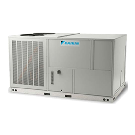
Packaged Gas / Electric Unit 7.5-12.5 Ton Direct Drive
Light Commercial DFG Models
Installation Instructions
This forced air central unit design complies with
requirements embodied in The American National Standard
/ National Standard of Canada ANSI Z21.47•CSA-2.3 Gas-
fired central furnaces.
©2022
IOD-1059
12/2022
ナンバー :
B150
会社名 :
DAIKIN COMFORT TECHNOLOGIES MANUFACTURING, L.P.
作 成日 :
2022/2/25
Our continuing commitment to quality products may mean a change in specifications without notice.
19001 Kermier Rd., Waller, TX 77484
ONLY PERSONNEL THAT HAVE BEEN TRAINED TO INSTALL, ADJUST,
SERVICE, MAINTENANCE OR REPAIR
(HEREINAFTER, "SERVICE") THE EQUIPMENT SPECIFIED IN THIS
MANUAL SHOULD
SERVICE THE EQUIPMENT. THE MANUFACTURER WILL NOT BE
RESPONSIBLE FOR ANY INJURY OR PROPERTY DAMAGE ARISING
FROM IMPROPER SERVICE OR SERVICE PROCEDURES. IF YOU SERVICE
THIS UNIT, YOU ASSUME RESPONSIBILITY FOR ANY INJURY OR
PROPERTY
DAMAGE WHICH MAY RESULT. IN ADDITION, IN
JURISDICTIONS THAT REQUIRE ONE OR MORE LICENSES TO SERVICE
THE EQUIPMENT SPECIFIED IN THIS
MANUAL, ONLY LICENSED PERSONNEL SHOULD SERVICE THE
EQUIPMENT.
IMPROPER INSTALLATION, ADJUSTMENT, SERVICING, MAINTENANCE
OR REPAIR OF THE EQUIPMENT SPECIFIED IN THIS MANUAL,
OR ATTEMPTING TO INSTALL, ADJUST, SERVICE OR REPAIR THE
EQUIPMENT SPECIFIED IN THIS MANUAL WITHOUT PROPER
TRAINING MAY RESULT IN PRODUCT DAMAGE, PROPERTY DAMAGE,
PERSONAL
INJURY OR DEATH.
DO NOT BYPASS SAFETY DEVICES
www.daikincomfort.com
INSTALLATION INSTRUCTIONS
WARNING
WARNING

Advertisement

Table of Contents
loading
Need help?

Need help?

Do you have a question about the DFG Series and is the answer not in the manual?

Questions and answers

Subscribe to Our Youtube Channel

Summary of Contents for Daikin DFG Series

  • Page 1 / National Standard of Canada ANSI Z21.47•CSA-2.3 Gas- fired central furnaces. ナンバー : B150 会社名 : DAIKIN COMFORT TECHNOLOGIES MANUFACTURING, L.P. 作 成日 : 2022/2/25 Our continuing commitment to quality products may mean a change in specifications without notice. ©2022 19001 Kermier Rd., Waller, TX 77484...
  • Page 2: Table Of Contents

    Electrical wiring ............10 gas supply piping ............13 EQUIPMENT SUPPORT Propane gas installations ........15 Daikin North America LLC Circulating Air and Filters ........16 19001 Kermier Road Venting ................16 Waller, Texas 77484 Condensate Drain Connection .........
  • Page 3 WARNING WARNING FIRE OR EXPLOSION HAZARD To avoid property damage, personal injury or death, do not use this unit if any part has been Failure to follow the safety warnings exactly could result in under water. Immediately call a qualified service serious injury, death or property damage.
  • Page 4 WARNING CARBON MONOXIDE POISONING HAZARD Failure to follow the steps outlined below for each appliance connected to the venting system being placed into operation could result in carbon monoxide poisoning or death. The following steps shall be followed with each appliance connected to the venting system placed in operation, while any other appliances connected to the venting system are not in CARBON MONOXIDE POISONING HAZARD...
  • Page 5: General Information

    Specification sheets can be found at www. du Code d’installation du gaz naturel et du propane, CSA B149.1 daikinac.com for Daikin brand products. Within the website, et à ces instructions. Vérifier qu’il n’y a pas d’obstruction ou please select the residential or commercial products menu de restriction, de fuite, de corrosion et d’autres problèmes qui...
  • Page 6 Obtain from: American National Standards Institute WARNING www.ansi.org System design and installation should also, where To prevent possible equipment damage, property applicable, follow information presented in accepted damage, personal injury or death, the following industry guides such as the ASHRAE Handbooks. The bullet points must be observed when installing the unit.
  • Page 7 • Allow minimum clearances from the enclosure for • Do not skid or slide on any surface as this may fire protection, proper operation, and service access damage unit base. The unit must be stored on a flat, (see unit clearances). These clearances must be level surface.
  • Page 8: Clearances

    See the manual shipped with the roof curb for assembly and installation instructions. CLEARANCES Roof Curb Installation Figure 2 ROOF CURB POST-INSTALLATION CHECKS After installation, check the top of the curb, duct connection frame and duct flanges to make sure gasket has been applied properly.
  • Page 9: Rigging Details

    • Two spreader bars must span over the unit to prevent damage to the cabinet by the lift cables. Spreader bars must be of sufficient length so that cables do not come in contact with the unit during transport. 1" Remove wood struts mounted beneath unit base frame before setting unit on roof curb.
  • Page 10: Weights And Center Of Gravity

    Refer to the Roof Curb Installation Instructions for proper DFG Weights (lbs) curb installation. Curbing must be installed in compliance Data with the National Roofing Contractors Association Manual. Corner Weight - A Corner Weight - B Corner Weight - C Corner Weight - D Unit Shipping Weight 1140...
  • Page 11 Main power wiring should be sized for the minimum circuit ampacity shown on the unit’s database. Size wires in WARNING accordance with the ampacity tables in Article 310 of the National Electrical Code. If long wires are required, it HIGH VOLTAGE! may be necessary to increase the wire size to prevent To avoid personal injury or death due to electrical shock, do not...
  • Page 12 Areas Without Convenience Outlet It is recommended that an independent 115V power source be brought to the vicinity of the roof top unit for portable lights and tools used by the service mechanic. NOTE: Refer to local codes for requirements. These outlets can also be factory installed.
  • Page 13: Gas Supply Piping

    "Through the Base Pan Kit" Part Numbers WARNING TTBCKHE02 To avoid property damage, personal injury or TTBCKHE02FI (Factory Kit) death when either using propane gas alone or at higher altitudes, obtain and install the Low Voltage Control Wiring proper conversion kit(s). Failure to do so can result in unsatisfactory operation and/or 1.
  • Page 14 The gas line installation must comply with local codes, or • In the prior two methods above the connector in the absence of local codes, with the latest edition of the or tubing must be protected from physical National Fuel Gas Code NFPA 54 / ANSI Z223.1. and thermal damage.
  • Page 15: Propane Gas Installations

    Tanks and Piping Complete information regarding tank sizing for WARNING vaporization, recommended regulator settings and pipe sizing is available from most regulator manufacturers and To avoid property damage or personal injury, be propane gas suppliers. sure there is no open flame in the vicinity during air bleeding.
  • Page 16: Circulating Air And Filters

    NOTE: The gas connection size at the unit does NOT 7. There must be no obstruction to prevent the flow of establish the size of the supply line. combustion and ventilating air. A vent stack is not 3. These units are designed for either natural or required and must never be used.
  • Page 17: Startup, Adjustments, And Checks

    Pre-Startup Instructions - General Base Rail CAUTION Open Vent 2” Min To prevent property damage or personal injury, do not start the unit until all necessary pre- checks and tests have been performed. See NOTE Prior to the beginning of Startup, Adjustments, and Checks procedures, the following steps should be completed in the building.
  • Page 18: Air Flow Adjustments

    range as indicated in Appendix B Electrical Data. Contractor Responsibility System Voltage - That nominal voltage value assigned The installing contractor must be certain that: to a circuit or system for the purpose of designating its • All supply and return air ductwork is in place, properly voltage class.
  • Page 19 DFG Model Wiring GR (FAN) Energized during Heat Mode BR (Heating Stage 2) PU (Cooling Stage 2) ** TB1-DH is energized when the unit is in heat mode. When TB1-DH is energized, the blower motor WH (Heating Stage 1) operates at a new group of programmed speeds, T6-T10, in place of T1-T5.
  • Page 20: Gas System Check

    The supply gas pressure should be adjusted to 7.0” w.c. How to set Fan Speed on natural gas and 11.0” on LP gas with the gas burners operating. If there is more than one unit on a common gas Set Evaporator Fan Rpm line, the pressures should be checked with all units under Actual RPM’s must be set and verified with a tachometer full fire.
  • Page 21 manifold pressure to obtain rating, it is mandatory INLET GAS PRESSURE that the input be adjusted at the installation site. NATURAL Mi n. 5.0" W.C., Ma x. 10.0" W.C. All installations should be made as outlined in the latest edition of the National Fuel Gas Code PROPANE Mi n.
  • Page 22 2. With the unit operating, time the smallest dial on the meter for one complete revolution. If this is a 2 cubic To remove manometer from gas valve: foot dial, divide the seconds by 2; if it is a 1 cubic foot 1.
  • Page 23: Normal Sequence Of Operation

    NOTE: Blower speed MUST be set to give the fan circulates air across the heat exchanger and correct air temperature rise through the unit as delivers heated air to the conditioned space. marked on the rating plate. 10. When the space temperature rises, the thermostat will open R-W.
  • Page 24 Refrigeration System Checks 1. Current through primary winding of transformer This unit is equipped with thermal expansion valves. TRANS1 energizes the 24-volt control circuit. 2. To simulate a mechanical call for cooling from the wall Ensure the hold-down bolts on the compressor are secure thermostat, place a jumper across terminals R and Y1 and have not vibrated loose during shipment.
  • Page 25 8. With all safety devices closed, the system will Refrigeration Performance Check continue cooling operation until the thermostat is Check that compressor RLA corresponds to values shown satisfied. in Appendix B. RLA draw can be much lower than values 9. Disconnecting the jumper wire between R and Y1 and listed at low load conditions and low ambient condensing Y2 and between R and G on TB1 terminal block will temperatures.
  • Page 26: Maintenance

    CHECKING SUBCOOLING coil liquid line. See Design Superheat and Subcooling table NOTE: Units with a TXV should be charged to for targets on each model. Subcooling only. Make sure the air flow is correct before making any adjustments. (Units with Expansion Valve (TXV)) EXAMPLE: a.
  • Page 27 Filters WARNING CAUTION HIGH VOLTAGE! To prevent property damage due to fire and loss Disconnect all power before of equipment efficiency or equipment damage due servicing or installing this unit. to dust and lint build up on internal parts, never Multiple power sources may be operate unit without an air filter installed in the present.
  • Page 28: Troubleshooting

    Lubrication The fan shaft bearings, the supply fan motors, the WARNING condenser fan motors and compressors are permanently lubricated. To avoid personal injury or death due to electric shock, do not remove any internal compartment Inspection & Cleaning covers or attempt any adjustment. Contact a qualified servicer at once if an abnormal flame All flue product carrying areas of the furnace, its vent should develop.
  • Page 29 cycle begins, and the induced draft blower remains on. If flame is established but lost, the control will energize The diagnostic fault code is two flashes. the circulator blower at the heat speed and then begin a new ignition sequence. If flame is established then lost on Pressure Switch Stuck Closed (3 FLASH CODE) subsequent attempts, the control will recycle for four (4)
  • Page 30: Appendix A Blower Performance Data

    APPENDIX A BLOWER PERFORMANCE DATA 7.5 TON GE 7.5T 130K 5 burner Standard Static Motor 2.4 HP Model: DFG090_STD DOWNSHOT HORIZONTAL TAP SPEED SCFM R.P.M. WATTS TAP SPEED SCFM R.P.M. WATTS 2085.3 507.0 211.3 0.33 2077.0 497.6 226.7 0.33 1907.6 574.2 247.2 0.38...
  • Page 31 APPENDIX A BLOWER PERFORMANCE DATA 7.5 TON GE 7.5T 130K 5 burner Medium Static Motor 2.4 HP Model: DFG090_MED DOWNSHOT HORIZONTAL TAP SPEED SCFM R.P.M. WATTS Torque TAP SPEED SCFM R.P.M. WATTS Torque 2159.2 517.7 233.9 0.37 3.70 2152.5 508.0 245.4 0.36 3.70...
  • Page 32 APPENDIX A BLOWER PERFORMANCE DATA 7.5 TON GE 7.5T 130K 5 burner High Static Motor 2.4 HP Model: DFG090_HIGH DOWNSHOT HORIZONTAL TAP SPEED SCFM R.P.M. WATTS TAP SPEED SCFM R.P.M. WATTS 2304.2 538.8 279.5 0.43 2298.6 528.4 283.9 0.42 2132.0 601.7 314.8 0.48...
  • Page 33 APPENDIX A BLOWER PERFORMANCE DATA 7.5 TON GE 7.5T 180K 6 burner Standard Static Motor 2.4 HP Model: DFG090_STD DOWNSHOT HORIZONTAL TAP SPEED SCFM R.P.M. WATTS TAP SPEED SCFM R.P.M. WATTS 1888.7 503.5 209.1 0.30 1995.7 475.9 199.1 0.28 1815.1 537.9 218.3 0.32...
  • Page 34 APPENDIX A BLOWER PERFORMANCE DATA 7.5 TON GE 7.5T 180K 6 burner Medium Static Motor 2.4 HP Model: DFG090_MED DOWNSHOT HORIZONTAL TAP SPEED SCFM R.P.M. WATTS TAP SPEED SCFM R.P.M. WATTS 2136.4 542.3 272.9 0.41 2249.8 511.9 258.3 0.39 2047.0 579.6 287.7 0.44...
  • Page 35 APPENDIX A BLOWER PERFORMANCE DATA 7.5 TON GE 7.5T 180K 6 burner High Static Motor 3.5 HP Model: DFG090_HIGH DOWNSHOT HORIZONTAL TAP SPEED SCFM R.P.M. WATTS TAP SPEED SCFM R.P.M. WATTS 2307.0 568.9 321.4 0.49 2424.7 536.7 303.8 0.46 2207.7 608.1 339.8 0.52...
  • Page 36 APPENDIX A BLOWER PERFORMANCE DATA 7.5 TON GE 7.5T 225K 7 burner Standard Static Motor 2.4 HP Model: DFG090_STD DOWNSHOT HORIZONTAL TAP SPEED SCFM R.P.M. WATTS TAP SPEED SCFM R.P.M. WATTS 1929.7 526.8 419.1 0.31 1990.9 484.9 392.3 0.29 1730.8 593.8 459.0 0.35...
  • Page 37 APPENDIX A BLOWER PERFORMANCE DATA 7.5 TON GE 7.5T 225K 7 burner Medium Static Motor 2.4 HP Model: DFG090_MED DOWNSHOT HORIZONTAL TAP SPEED SCFM R.P.M. WATTS TAP SPEED SCFM R.P.M. WATTS 2136.3 560.5 505.7 0.40 2210.0 514.7 472.7 0.37 1958.0 620.0 548.5 0.44...
  • Page 38 APPENDIX A BLOWER PERFORMANCE DATA 7.5 TON GE 7.5T 225K 7 burner High Static Motor 3.5 HP Model: DFG090_HIGH DOWNSHOT HORIZONTAL TAP SPEED SCFM R.P.M. WATTS TAP SPEED SCFM R.P.M. WATTS 2284.0 584.7 572.2 0.47 2366.4 536.1 534.4 0.43 2119.7 639.1 617.1 0.51...
  • Page 39 APPENDIX A BLOWER PERFORMANCE DATA 8.5 TON GE 8.5T 130K 5 burner Standard Static Motor 2.4 HP Model: DFG102_STD DOWNSHOT HORIZONTAL TAP SPEED SCFM R.P.M. WATTS TAP SPEED SCFM R.P.M. WATTS 2071.2 505.1 208.1 0.33 2062.9 495.5 222.9 0.32 1893.1 572.5 243.9 0.37...
  • Page 40 APPENDIX A BLOWER PERFORMANCE DATA 8.5 TON GE 8.5T 130K 5 burner Medium Static Motor 3.5 HP Model: DFG102_MED DOWNSHOT HORIZONTAL TAP SPEED SCFM R.P.M. WATTS TAP SPEED SCFM R.P.M. WATTS 2246.3 530.4 260.9 0.40 2240.6 520.3 268.4 0.39 2072.7 594.4 296.3 0.45...
  • Page 41 APPENDIX A BLOWER PERFORMANCE DATA 8.5 TON GE 8.5T 130K 5 burner High Static Motor 3.5 HP Model: DFG102_HIGH DOWNSHOT HORIZONTAL TAP SPEED SCFM R.P.M. WATTS TAP SPEED SCFM R.P.M. WATTS 2388.0 550.9 305.7 0.47 2384.4 540.3 307.5 0.46 2218.0 612.2 340.9 0.52...
  • Page 42 APPENDIX A BLOWER PERFORMANCE DATA 8.5 TON GE 8.5T 180K 6 burner Standard Static Motor 2.4 HP Model: DFG102_STD DOWNSHOT HORIZONTAL TAP SPEED SCFM R.P.M. WATTS TAP SPEED SCFM R.P.M. WATTS 1996.1 520.4 235.8 0.34 2106.0 491.5 223.8 0.32 1915.5 556.0 247.5 0.37...
  • Page 43 APPENDIX A BLOWER PERFORMANCE DATA 8.5 TON GE 8.5T 180K 6 burner Medium Static Motor 3.5 HP Model: DFG102_MED DOWNSHOT HORIZONTAL TAP SPEED SCFM R.P.M. WATTS TAP SPEED SCFM R.P.M. WATTS 2239.4 558.4 301.7 0.45 2355.4 526.9 285.3 0.43 2143.9 596.8 318.7 0.48...
  • Page 44 APPENDIX A BLOWER PERFORMANCE DATA 8.5 TON GE 8.5T 180K 6 burner High Static Motor 3.5 HP Model: DFG102_HIGH DOWNSHOT HORIZONTAL TAP SPEED SCFM R.P.M. WATTS TAP SPEED SCFM R.P.M. WATTS 2393.6 582.5 347.5 0.54 2513.3 549.4 328.4 0.50 2289.5 622.4 367.8 0.57...
  • Page 45 APPENDIX A BLOWER PERFORMANCE DATA 8.5 TON GE 8.5T 225K 7 burner Standard Static Motor 2.4 HP Model: DFG102_STD DOWNSHOT HORIZONTAL TAP SPEED SCFM R.P.M. WATTS TAP SPEED SCFM R.P.M. WATTS 2037.9 544.4 463.5 0.36 2105.6 500.5 433.5 0.33 1849.9 607.5 504.9 0.40...
  • Page 46 APPENDIX A BLOWER PERFORMANCE DATA 8.5 TON GE 8.5T 225K 7 burner Medium Static Motor 3.5 HP Model: DFG102_MED DOWNSHOT HORIZONTAL TAP SPEED SCFM R.P.M. WATTS TAP SPEED SCFM R.P.M. WATTS 2298.5 587.1 579.0 0.48 2381.8 538.2 540.7 0.44 2135.6 641.0 624.1 0.52...
  • Page 47 APPENDIX A BLOWER PERFORMANCE DATA 8.5 TON GE 8.5T 225K 7 burner High Static Motor 3.5 HP Model: DFG102_HIGH DOWNSHOT HORIZONTAL TAP SPEED SCFM R.P.M. WATTS TAP SPEED SCFM R.P.M. WATTS 2377.5 600.0 616.6 0.52 2465.4 549.7 575.5 0.47 2221.9 651.4 662.8 0.56...
  • Page 48 APPENDIX A BLOWER PERFORMANCE DATA 10 TON GE 10T 130K 5 burner Standard Static Motor 3.5 HP Model: DFG120_STD DOWNSHOT HORIZONTAL TAP SPEED SCFM R.P.M. WATTS TAP SPEED SCFM R.P.M. WATTS 2115.6 500.0 227.8 0.35 2044.3 494.2 367.1 0.34 PL Rated TAP 1 PL Rated TAP 1...
  • Page 49 APPENDIX A BLOWER PERFORMANCE DATA 10 TON GE 10T 130K 5 burner Medium Static Motor 5 HP Model: DFG120_MED DOWNSHOT HORIZONTAL TAP SPEED SCFM R.P.M. WATTS TAP SPEED SCFM R.P.M. WATTS 2371.4 572.6 546.2 0.51 2468.4 525.2 497.3 0.47 2176.8 639.0 599.8 0.57...
  • Page 50 APPENDIX A BLOWER PERFORMANCE DATA 10 TON GE 10T 130K 5 burner High Static Motor 5 HP Model: DFG120_HIGH DOWNSHOT HORIZONTAL TAP SPEED SCFM R.P.M. WATTS TAP SPEED SCFM R.P.M. WATTS 2536.5 594.3 627.3 0.58 2640.5 545.2 573.6 0.53 2351.7 657.9 683.0 0.64...
  • Page 51 APPENDIX A BLOWER PERFORMANCE DATA 10 TON GE 10T 180K 6 burner Standard Static Motor 3.5 HP Model: DFG120_STD DOWNSHOT HORIZONTAL TAP SPEED SCFM R.P.M. WATTS TAP SPEED SCFM R.P.M. WATTS 2163.8 528.9 460.1 0.37 2304.4 479.3 358.6 0.33 2064.6 562.5 411.8 0.39...
  • Page 52 APPENDIX A BLOWER PERFORMANCE DATA 10 TON GE 10T 180K 6 burner Medium Static Motor 3.5 HP Model: DFG120_MED DOWNSHOT HORIZONTAL TAP SPEED SCFM R.P.M. WATTS TAP SPEED SCFM R.P.M. WATTS 2409.6 560.9 551.4 0.47 2548.5 505.6 437.4 0.42 2232.9 621.9 593.2 0.52...
  • Page 53 APPENDIX A BLOWER PERFORMANCE DATA 10 TON GE 10T 180K 6 burner High Static Motor 5 HP Model: DFG120_HIGH DOWNSHOT HORIZONTAL TAP SPEED SCFM R.P.M. WATTS TAP SPEED SCFM R.P.M. WATTS 2589.3 586.0 654.7 0.56 2516.5 535.8 541.4 0.51 2393.4 657.8 716.2 0.63...
  • Page 54 APPENDIX A BLOWER PERFORMANCE DATA 10 TON GE 10T 240K 7 burner Standard Static Motor 3.5 HP Model: DFG120_STD DOWNSHOT HORIZONTAL TAP SPEED SCFM R.P.M. WATTS TAP SPEED SCFM R.P.M. WATTS 2168.6 554.6 276.5 0.43 2325.3 498.4 255.7 0.38 2029.1 591.7 294.1 0.46...
  • Page 55 APPENDIX A BLOWER PERFORMANCE DATA 10 TON GE 10T 240K 7 burner Medium Static Motor 3.5 HP Model: DFG120_MED DOWNSHOT HORIZONTAL TAP SPEED SCFM R.P.M. WATTS TAP SPEED SCFM R.P.M. WATTS 2435.1 597.2 365.7 0.56 2576.3 538.6 339.0 0.50 2204.6 670.2 411.4 0.63...
  • Page 56 APPENDIX A BLOWER PERFORMANCE DATA 10 TON GE 10T 240K 7 burner High Static Motor 5 HP Model: DFG120_HIGH DOWNSHOT HORIZONTAL TAP SPEED SCFM R.P.M. WATTS TAP SPEED SCFM R.P.M. WATTS 2634.8 629.7 455.0 0.67 2794.6 567.9 415.8 0.60 2422.9 697.1 499.5 0.74...
  • Page 57 APPENDIX A BLOWER PERFORMANCE DATA 12.5 TON GE 12.5T 130K 5 burner Standard Static Motor 3.5 HP Model: DFG150_STD DOWNSHOT HORIZONTAL TAP SPEED SCFM R.P.M. WATTS TAP SPEED SCFM R.P.M. WATTS 2212.1 510.9 226.7 0.33 2299.1 481.1 216.7 0.31 1878.6 608.8 270.5 0.40...
  • Page 58 APPENDIX A BLOWER PERFORMANCE DATA 12.5 TON GE 12.5T 130K 5 burner Medium Static Motor 5 HP Model: DFG150_MED DOWNSHOT HORIZONTAL TAP SPEED SCFM R.P.M. WATTS TAP SPEED SCFM R.P.M. WATTS 2495.8 542.1 291.5 0.44 2431.2 514.9 276.5 0.42 2223.1 623.7 330.1 0.51...
  • Page 59 APPENDIX A BLOWER PERFORMANCE DATA 12.5 TON GE 12.5T 130K 5 burner High Static Motor 5 HP Model: DFG150_HIGH DOWNSHOT HORIZONTAL TAP SPEED SCFM R.P.M. WATTS TAP SPEED SCFM R.P.M. WATTS 2703.7 571.6 367.7 0.54 2652.8 543.4 348.2 0.51 PL Rated TAP 1 PL Rated TAP 1...
  • Page 60 APPENDIX A BLOWER PERFORMANCE DATA 12.5 TON GE 12.5T 180K 6 burner Standard Static Motor 3.5 HP Model: DFG150_STD DOWNSHOT HORIZONTAL TAP SPEED SCFM R.P.M. WATTS TAP SPEED SCFM R.P.M. WATTS 2192.9 557.2 268.9 0.39 2396.2 492.8 242.2 0.35 1886.6 632.8 302.4 0.45...
  • Page 61 APPENDIX A BLOWER PERFORMANCE DATA 12.5 TON GE 12.5T 180K 6 burner Medium Static Motor 5 HP Model: DFG150_MED DOWNSHOT HORIZONTAL TAP SPEED SCFM R.P.M. WATTS TAP SPEED SCFM R.P.M. WATTS 2459.5 565.5 313.6 0.49 2601.3 527.1 317.0 0.45 2245.1 639.9 355.8 0.55...
  • Page 62 APPENDIX A BLOWER PERFORMANCE DATA 12.5 TON GE 12.5T 180K 6 burner High Static Motor 5 HP Model: DFG150_HIGH DOWNSHOT HORIZONTAL TAP SPEED SCFM R.P.M. WATTS TAP SPEED SCFM R.P.M. WATTS 2636.4 591.6 378.5 0.57 2780.4 549.9 374.0 0.53 2434.3 661.5 420.5 0.64...
  • Page 63 APPENDIX A BLOWER PERFORMANCE DATA 12.5 TON GE 12.5T 240K 7 burner Standard Static Motor 3.5 HP Model: DFG150_STD DOWNSHOT HORIZONTAL TAP SPEED SCFM R.P.M. WATTS TAP SPEED SCFM R.P.M. WATTS 2200.9 591.0 313.5 0.45 2475.9 504.7 276.2 0.39 1963.0 656.1 344.1 0.50...
  • Page 64 APPENDIX A BLOWER PERFORMANCE DATA 12.5 TON GE 12.5T 240K 7 burner Medium Static Motor 5 HP Model: DFG150_MED DOWNSHOT HORIZONTAL TAP SPEED SCFM R.P.M. WATTS TAP SPEED SCFM R.P.M. WATTS 2550.8 625.2 415.3 0.60 2756.2 546.9 361.5 0.53 2344.9 687.2 450.1 0.66...
  • Page 65 APPENDIX A BLOWER PERFORMANCE DATA 12.5 TON GE 12.5T 240K 7 burner High Static Motor 5 HP Model: DFG150_HIGH DOWNSHOT HORIZONTAL TAP SPEED SCFM R.P.M. WATTS TAP SPEED SCFM R.P.M. WATTS 2550.8 625.2 415.3 0.60 2756.2 546.9 361.5 0.53 2344.9 687.2 450.1 0.66...
  • Page 66: Appendix B Electrical Data

    APPENDIX B ELECTRICAL DATA Electrical Data Optional Powered Optional Power Electrical Compressor Outdoor Fan Motor Indoor Fan Motor Optional Electric Heat Power Supply Model Number Convienience Outlet Exhaust Rating Type Part # Direct 41.6/41.6 50/50 Drive 9.6/8.7 51.2/50.3 60/60 DFG0903D 208/230/3/60 13.1 83.1...
  • Page 67 APPENDIX B ELECTRICAL DATA Electrical Data Optional Powered Optional Power Electrical Compressor Outdoor Fan Motor Indoor Fan Motor Optional Electric Heat Power Supply Model Number Convienience Outlet Exhaust Rating Type Part # Direct 44.6/44.6 50/50 Drive 9.6/8.7 54.2/53.3 60/60 DFG1023D 208/230/3/60 14.5 0.33...
  • Page 68 APPENDIX B ELECTRICAL DATA Electrical Data Optional Powered Optional Power Electrical Compressor Outdoor Fan Motor Indoor Fan Motor Optional Electric Heat Power Supply Model Number Convienience Outlet Exhaust Rating Type Part # Direct 50.1/50.1 60/60 Drive 9.6/8.7 59.7/58.8 70/70 DFG1203D 208/230/3/60 15.6 0.33...
  • Page 69 APPENDIX B ELECTRICAL DATA Electrical Data Optional Powered Optional Power Electrical Compressor Outdoor Fan Motor Indoor Fan Motor Optional Electric Heat Power Supply Model Number Convienience Outlet Exhaust Rating Type Part # Direct 59.1/59.1 70/70 Drive 9.6/8.7 68.7/67.8 80/80 DFG1503D 208/230/3/60 10.9 Standard...
  • Page 70: Appendix C Unit Dimensions

    APPENDIX C UNIT DIMENSIONS MODEL 59-3/4" DFG090-150 93-1/4" 54-58 54-5/8" 5-7/8" 93-7/8" 60-3/8" 1" Figure 17 13" RETURN 12.5" X 36.4" SUPPLY 13.9" X 28.3" 9-1/2" Horizontal Discharge Figure 16 19-11/16 NOTE NOTE For horizontal discharge, remove supply and return For horizontal discharge, remove supply and return 6-5/8 RETURN...
  • Page 71: Appendix D Min-Max Airflow

    APPENDIX D MIN-MAX AIRFLOW RECOMMENDED MIN-MAX AIRFLOW RANGE HIGH FIRE RATE HEATING COOLING UNIT MAXIMUM SCFM BTU/HR MINIMUM SCFM MINIMUM SCFM DFG090 210,000 2250 2360 3690 DFG102 210,000 2550 2680 4230 DFG120 210,000 3000 3150 4860 DFG150 210,000 3750 3940 6070...
  • Page 72 Wiring is subject to change. Always refer to the wiring diagram on the unit for the most up-to-date wiring.
  • Page 75 PAGE LEFT INTENTIONALLY BLANK...
  • Page 76 CUSTOMER FEEDBACK Daikin is very interested in all product comments. Please fill out the feedback form on the following link: https://daikincomfort.com/contact-us You can also scan the QR code on the right to be directed to the feedback page. PRODUCT REGISTRATION Thank you for your recent purchase.

This manual is also suitable for:

Dfg090Dfg102Dfg120Dfg150

Table of Contents

Save PDF