Daikin DFC Series Installation Instructions Manual
Packaged heating and cooling unit
Hide thumbs
Also See for DFC Series:
- Installation instructions manual (72 pages) ,
- Installation instructions manual (60 pages)
Advertisement
Table of Contents
- 1 Table of Contents
- 2 Safety Instructions
- 3 Replacement Parts
- 4 General Information
- 5 Unit Location
- 6 Clearances
- 7 Roof Curb Post-Installation Checks
- 8 Roof Top Duct Connections
- 9 Rigging Details
- 10 Electrical Wiring
- 11 Circulating Air and Filters
- 12 Condensate Drain Connection
- 13 Startup, Adjustments, and Checks
- 14 Air Flow Adjustments
- Download this manual
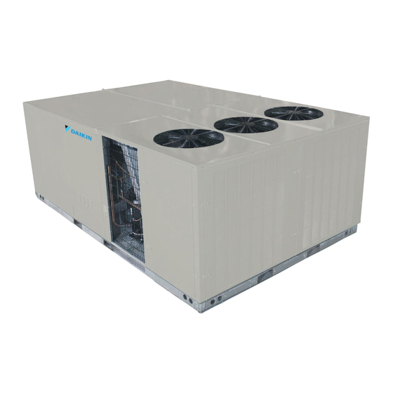
DFC
SERIES
P
H
ackaged
eating and
15 to 25 t
on
NOTE: 25 ton model shown in picture.
20 ton model has 4 fans
15 ton model has 3 fans
RECOGNIZE THIS SYMBOL
AS A SAFETY PRECAUTION.
These installation instructions cover the outdoor installation of
single package heating and cooling units. See the Specification
Sheet applicable to your model for information regarding
accessories.
*NOTE: Please contact your distributor or our website for the
applicable Specification Sheet referred to in this manual.
©2022
IOD-1054A
09/2022
c
U
ooling
nit
Our continuing commitment to quality products may mean a change in specifications without notice.
19001 Kermier Rd. Waller, TX 77484
www.daikincomfort.com
INSTALLATION INSTRUCTIONS
ONLY PERSONNEL THAT HAVE BEEN TRAINED TO INSTALL,
ADJUST, SERVICE, MAINTENANCE OR REPAIR
(HEREINAFTER, "SERVICE") THE EQUIPMENT SPECIFIED IN
THIS MANUAL SHOULD
SERVICE THE EQUIPMENT. THE MANUFACTURER WILL
NOT BE RESPONSIBLE FOR ANY INJURY OR PROPERTY
DAMAGE ARISING FROM IMPROPER SERVICE OR SERVICE
PROCEDURES. IF YOU SERVICE THIS UNIT, YOU ASSUME
RESPONSIBILITY FOR ANY INJURY OR PROPERTY
DAMAGE WHICH MAY RESULT. IN ADDITION, IN
JURISDICTIONS THAT REQUIRE ONE OR MORE LICENSES
TO SERVICE THE EQUIPMENT SPECIFIED IN THIS
MANUAL, ONLY LICENSED PERSONNEL SHOULD SERVICE
THE EQUIPMENT.
IMPROPER INSTALLATION, ADJUSTMENT, SERVICING,
MAINTENANCE OR REPAIR OF THE EQUIPMENT SPECIFIED
IN THIS MANUAL, OR ATTEMPTING TO INSTALL, ADJUST,
SERVICE OR REPAIR THE EQUIPMENT SPECIFIED IN THIS
MANUAL WITHOUT PROPER TRAINING MAY RESULT IN
PRODUCT DAMAGE, PROPERTY DAMAGE, PERSONAL
INJURY OR DEATH.
DO NOT BYPASS SAFETY DEVICES
Safety Instructions .................................................................2
Replacement Parts ................................................................2
General Information ..............................................................2
Unit Location .........................................................................4
Clearances .............................................................................6
Roof Curb Post-Installation Checks.........................................6
Roof Top Duct Connections ....................................................6
Rigging Details .......................................................................6
Electrical Wiring ....................................................................7
Circulating Air and Filters .......................................................9
Condensate Drain Connection ...............................................9
Startup, Adjustments, and Checks .......................................10
Air flow Adjustments ...........................................................11
WARNING
WARNING
Index
Advertisement
Table of Contents

Related Manuals for Daikin DFC Series


Summary of Contents for Daikin DFC Series
-
Page 1: Table Of Contents
INSTALLATION INSTRUCTIONS SERIES WARNING ackaged eating and ooling 15 to 25 t ONLY PERSONNEL THAT HAVE BEEN TRAINED TO INSTALL, ADJUST, SERVICE, MAINTENANCE OR REPAIR (HEREINAFTER, “SERVICE”) THE EQUIPMENT SPECIFIED IN THIS MANUAL SHOULD SERVICE THE EQUIPMENT. THE MANUFACTURER WILL NOT BE RESPONSIBLE FOR ANY INJURY OR PROPERTY DAMAGE ARISING FROM IMPROPER SERVICE OR SERVICE PROCEDURES. -
Page 2: Safety Instructions
Specification sheets can be tified by the manufacturer for use with this unit. Serious found at www.daikinac.com for Daikin brand products. Within the property damage, personal injury, reduced unit performance website, please select the residential or commercial products menu and/or hazardous conditions may result from the use of such non-approved devices. -
Page 3: Unit Location
EPA Regulations c. Original invoice or certified copy thereof, showing trade and other discounts or reductions. Important: The United States Environmental Protection d. Copy of the inspection report issued by the carrier Agency (EPA) has issued various regulations regarding representative at the time damage is reported to the the introduction and disposal of refrigerants in this carrier. - Page 4 Unit Precautions construction and remodeling. Various commercial and industrial processes may also be sources of chlorine/ • Do not stand or walk on the unit. fluorine compounds. • Do not drill holes anywhere in panels or in the base frame •...
-
Page 5: Clearances
• Sufficient structural support must be determined prior to locating and mounting the curb and package unit. • Ductwork must be constructed using industry guidelines. The duct work must be placed into the roof curb before LIFT OVER APPROXIMATE CENTER OF UNIT mounting the package unit. -
Page 6: Roof Curb Post-Installation Checks
CAUTION Do not lift units two at a time. Provisions for forks have been included in the unit base fram. Minimum fork length is 72” to prevent damage to the unit. Provisions for forks have been included in the unit base frame. No other fork locations are approved. -
Page 7: Electrical Wiring
Remove spreader bars, lifting cables and other rigging equipment. CAUTION ELECTRICAL WIRING When unit is suspended, boards and shipping brace will drop when screws are removed. To prevent personal injury, STAND CLEAR. Remove fork hole brackets, boards and WARNING shipping brace from bottom of unit before placing units onto curb. - Page 8 CAUTION To avoid property damage or personal injury due to fire, use only copper conductors. CAUTION To prevent improper and dangerous operation due to wiring errors, label all wires prior to disconnection when servic- ing controls. Verify proper operation after servicing. NOTE: A weather-tight disconnect switch, properly sized for the unit total load must be installed.
-
Page 9: Circulating Air And Filters
be provided with an access panel large enough to inspect the air chamber downstream of the heat exchanger. A cover should be tightly attached to prevent air leaks. Ductwork dimensions are shown in the roof curb installation manual. If desired, supply and return duct connections to the unit may be made with flexible connections to reduce possible unit operating sound transmission. -
Page 10: Startup, Adjustments, And Checks
Contractor Responsibility airborne bacteria and spores. Periodic cleaning is necessary to prevent this build-up from plugging the drain. The installing contractor must be certain that: • All supply and return air ductwork is in place, properly sealed, and corresponds with installation instructions. STARTUP, ADJUSTMENTS, AND CHECKS •... -
Page 11: Air Flow Adjustments
Three Phase Models Note: On units with DDC controls installed, air flow adjustments 2) MAXIMUM VOLTAGE DEVIATIONS are made through settings in the DDC controller and speed tap FROM AVERAGE VOLTAGE 3) PERCENT VOLTAGE = 100 X adjustments are not required. Refer to the DDC User Manual for UNBALANCE 1) AVERAGE VOLTAGE details on making airflow adjustments. - Page 12 DRC Model Wiring GR (FAN) Energized during Heat Mode BR (Heating Stage 2) PU (Cooling Stage 2) ** TB1-DH is energized when the unit is in heat mode. When TB1-DH is energized, the blower motor WH (Heating Stage 1) operates at a new group of programmed speeds, T6-T10, in place of T1-T5.
- Page 13 Electrical Input Check ing superheat, run the unit in cooling for 15-20 minutes or until refrigerant pressures stabilize. Use the following guidelines and Make preliminary check of evaporator fan ampere draw and verify methods to check unit operation and ensure that the refrigerant that motor nameplate amps are not exceeded.
- Page 14 cooling operation until the thermostat is satisfied. Design Superheat & Subcooling 8. Disconnecting the jumper wire between R and Y1 and Y2 Expan- Outdoor Superheat Subcooling and between R and G on TB1 terminal block will simulate Model Circuit sion Ambent ±...
- Page 15 Filters STEP 1: Remove Surface Debris CAUTION Remove surface dirt, leaves, fibers, etc. with a vacuum cleaner (preferably with a brush or other soft attachment rather TO PREVENT PROPERTY DAMAGE DUE TO FIRE AND LOSS OF than a metal tube), compressed air blown from the inside EQUIPMENT EFFICIENCY OR EQUIPMENT DAMAGE DUE TO out, and/or a soft bristle (not wire!) brush.
- Page 16 & fin coils. It is advised to blow off or vacuum out the residual water from the coil to speed up drying and prevent pooling. Daikin recommends a quarterly cleaning of the coils, as the minimum. The cleaning frequency should be increased depending on the level of dirt/dust accumulation and the environment (e.g.,...
- Page 17 APPENDIX A BLOWER PERFORMANCE DATA DIRECT DRIVE - STANDARD DFC1803D Standard Static DFC2403D Standard Static Speed Tap Static Airflow RPM 1 RPM 2 BHP 1 BHP 2 Speed Tap Static Airflow RPM 1 RPM 2 BHP 1 BHP 2 3198 0.19 0.20 4426...
- Page 18 APPENDIX A BLOWER PERFORMANCE DATA DIRECT DRIVE - STANDARD DFC3003D Standard Static Speed Tap Static Airflow RPM 1 RPM 2 BHP 1 BHP 2 5835 0.57 0.56 5496 0.63 0.62 5095 0.67 0.70 4723 0.72 0.75 4182 0.79 0.81 3784 0.83 0.84 7123...
- Page 19 APPENDIX A BLOWER PERFORMANCE DATA DIRECT DRIVE - HIGH STATIC DFC1803D High Static Speed Tap Static Airflow RPM 1 RPM 2 BHP 1 BHP 2 Speed Tap Static Airflow RPM 1 RPM 2 BHP 1 BHP 2 6622 0.25 0.25 8163 1.33 1.23...
- Page 20 APPENDIX A BLOWER PERFORMANCE DATA DIRECT DRIVE - HIGH STATIC DFC2403D High Static Speed Tap Static Airflow RPM 1 RPM 2 BHP 1 BHP 2 Speed Tap Static Airflow RPM 1 RPM 2 BHP 1 BHP 2 6412 0.71 0.69 9125 1.74 1.65...
- Page 21 APPENDIX A BLOWER PERFORMANCE DATA DIRECT DRIVE - HIGH STATIC DFC3003D High Static Speed Tap Static Airflow RPM 1 RPM 2 BHP 1 BHP 2 Speed Tap Static Airflow RPM 1 RPM 2 BHP 1 BHP 2 7629 1.07 1.03 10268 2.58 2.41...
- Page 22 APPENDIX A BLOWER PERFORMANCE DATA MODELS: DFG1803WL, DFG1804WL, DFG1807WL STANDARD STATIC TO 3.5HP (0.2 ~1.2 ESP) RPM1 RPM2 DDC% BHP1 BHP2 RPM1 RPM2 DDC% BHP1 BHP2 RPM1 RPM2 DDC% BHP1 BHP2 3600 0.52 0.44 0.52 0.49 0.56 0.53 3900 0.50 0.42 0.52 0.48...
- Page 23 APPENDIX A BLOWER PERFORMANCE DATA MODELS: DFG1803DM, DFG1803DH, DFG1804DM, DFG1804DH, DFG1807DM, DFG1807DH STANDARD STATIC TO 3.5HP (0.2 ~1.2 ESP) RPM1 RPM2 DDC% BHP1 BHP2 RPM1 RPM2 DDC% BHP1 BHP2 RPM1 RPM2 DDC% BHP1 BHP2 3600 0.52 0.44 0.52 0.49 0.56 0.53 3900 0.50...
- Page 24 APPENDIX A BLOWER PERFORMANCE DATA MODELS: DFC1803D, DFC1804D, DFC1807D STANDARD STATIC TO 3.5HP (0.2 ~1.2 ESP) RPM1 RPM2 DDC% BHP1 BHP2 RPM1 RPM2 DDC% BHP1 BHP2 RPM1 RPM2 DDC% BHP1 BHP2 3600 0.36 0.38 0.41 0.41 0.52 0.50 3900 0.36 0.37 0.43 0.43...
- Page 25 APPENDIX A BLOWER PERFORMANCE DATA MODELS: DFG2403WL, DFG2404WL, DFG2407WL STANDARD STATIC TO 3.5HP (0.2 ~1.2 ESP) RPM1 RPM2 DDC% BHP1 BHP2 RPM1 RPM2 DDC% BHP1 BHP2 RPM1 RPM2 DDC% BHP1 BHP2 4800 0.47 0.42 0.59 0.53 0.70 0.65 5200 0.58 0.52 0.71 0.64...
- Page 26 APPENDIX A BLOWER PERFORMANCE DATA MODELS: DFG2403DM, DFG2403DH, DFG2404DM, DFG2404DH, DFG2407DM, DFG2407DH STANDARD STATIC TO 3.5HP (0.2 ~1.2 ESP) RPM1 RPM2 DDC% BHP1 BHP2 RPM1 RPM2 DDC% BHP1 BHP2 RPM1 RPM2 DDC% BHP1 BHP2 4800 0.47 0.42 0.59 0.53 0.70 0.65 5200 0.58...
- Page 27 APPENDIX A BLOWER PERFORMANCE DATA MODELS: DFC2403D, DFC2404D, DFC2407D STANDARD STATIC TO 3.5HP (0.2 ~1.2 ESP) RPM1 RPM2 DDC% BHP1 BHP2 RPM1 RPM2 DDC% BHP1 BHP2 RPM1 RPM2 DDC% BHP1 BHP2 4800 0.42 1.18 0.53 1.07 0.66 1.05 5200 0.48 1.17 0.61 1.07...
- Page 28 APPENDIX A ECONOMIZER PRESSURE DROP Airflow Pressure Drop of Downflow Economizer for 15 to 25 Ton Rooftop Units (100% Return Air) SCFM 4500 5000 5500 6000 6500 7000 7500 8000 8500 9000 9500 10000 (In WG) 0.15 0.18 0.22 0.27 0.32 0.37 0.42...
- Page 29 APPENDIX B ELECTRICAL DATA Optional Powered Optional Power Optional Power Exhaust Model Compressor Outdoor Fan Motor Indoor Fan Motor Optional Electric Heat Power Supply Electrical Rating Convienience Outlet Exhaust (Modulating) Number Part # 84.0/84.0 100/100 88.8/88.8 110/110 13.9 97.9/97.9 110/110 9.6/8.7 93.6/92.7 110/110...
- Page 30 APPENDIX B ELECTRICAL DATA Optional Powered Optional Power Optional Power Exhaust Model Compressor Outdoor Fan Motor Indoor Fan Motor Optional Electric Heat Power Supply Electrical Rating Convienience Outlet Exhaust (Modulating) Number Part # 32.2 34.2 40.5 35.7 37.7 44.0 47.1 49.6 57.5 EH**-7L30...
- Page 31 APPENDIX B ELECTRICAL DATA Optional Powered Optional Power Optional Power Exhaust Model Compressor Outdoor Fan Motor Indoor Fan Motor Optional Electric Heat Power Supply Electrical Rating Convienience Outlet Exhaust (Modulating) Number Part # 53.2 55.6 61.3 57.5 59.9 65.6 61.3 64.3 71.4 EH**-4L30...
- Page 32 APPENDIX B ELECTRICAL DATA Optional Powered Optional Power Optional Power Exhaust Model Compressor Outdoor Fan Motor Indoor Fan Motor Optional Electric Heat Power Supply Electrical Rating Convienience Outlet Exhaust (Modulating) Number Part # 151/151 175/175 155/155 200/200 13.9 165/165 200/200 9.6/8.7 160/159 200/200...
- Page 33 APPENDIX B ELECTRICAL DATA Optional Powered Optional Power Optional Power Exhaust Model Compressor Outdoor Fan Motor Indoor Fan Motor Optional Electric Heat Power Supply Electrical Rating Convienience Outlet Exhaust (Modulating) Number Part # 70.0 72.4 78.1 74.3 76.7 82.4 70.0 72.8 79.9 EH**-4L30...
- Page 34 APPENDIX C UNIT DIMENSIONS Model 15 Ton 133 - 7/8” 88 - 1/2” 51 - 11/16” 5 - 5/32” 20 Ton 133 - 7/8” 88 - 1/2” 5 - 5/32” 25 Ton NOTE: 15 ton models have 3 fans. 20 ton models have 4 fans 25 ton models have 5 fans 21”...
- Page 35 WIRING DIAGRAMS DFC180* Wiring is subject to change. Always refer to the wiring diagram on the unit for the most up-to-date wiring.
- Page 36 WIRING DIAGRAMS DFC180* Wiring is subject to change. Always refer to the wiring diagram on the unit for the most up-to-date wiring.
- Page 37 WIRING DIAGRAMS DFC240* Wiring is subject to change. Always refer to the wiring diagram on the unit for the most up-to-date wiring.
- Page 38 WIRING DIAGRAMS DFC240* Wiring is subject to change. Always refer to the wiring diagram on the unit for the most up-to-date wiring.
- Page 39 WIRING DIAGRAMS DFC300* Wiring is subject to change. Always refer to the wiring diagram on the unit for the most up-to-date wiring.
- Page 40 WIRING DIAGRAMS DFC300* Wiring is subject to change. Always refer to the wiring diagram on the unit for the most up-to-date wiring.
- Page 41 WIRING DIAGRAMS DFC180* DDC Wiring is subject to change. Always refer to the wiring diagram on the unit for the most up-to-date wiring.
- Page 42 DFC180* DDC WIRING DIAGRAMS Wiring is subject to change. Always refer to the wiring diagram on the unit for the most up-to-date wiring.
- Page 43 DFC240* DDC WIRING DIAGRAMS Wiring is subject to change. Always refer to the wiring diagram on the unit for the most up-to-date wiring.
- Page 44 DFC240* DDC WIRING DIAGRAMS Wiring is subject to change. Always refer to the wiring diagram on the unit for the most up-to-date wiring.
- Page 45 DFC300* DDC WIRING DIAGRAMS Wiring is subject to change. Always refer to the wiring diagram on the unit for the most up-to-date wiring.
- Page 46 DFC300* DDC WIRING DIAGRAMS Wiring is subject to change. Always refer to the wiring diagram on the unit for the most up-to-date wiring.
- Page 49 THIS PAGE INTENTIONALLY LEFT BLANK...
- Page 50 THIS PAGE INTENTIONALLY LEFT BLANK...
- Page 51 THIS PAGE INTENTIONALLY LEFT BLANK...
- Page 52 CUSTOMER FEEDBACK Daikin is very interested in all product comments. Please fill out the feedback form on the following link: https://daikincomfort.com/contact-us You can also scan the QR code on the right to be directed to the feedback page. Our continuing commitment to quality products may mean a change in specifications without notice.
Need help?
Do you have a question about the DFC Series and is the answer not in the manual?
Questions and answers