Table of Contents
Advertisement
Handbuch/Manual
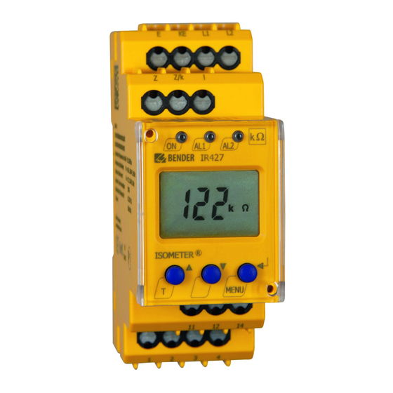
ISOMETER® IR427 plus MK7
Isolationsüberwachungsgerät
und Meldekombination
Bestimmungsgemäße Verwendung
®
Das ISOMETER
IR427 überwacht den Isolationswiderstand R
nes medizinischen IT-Systems mit AC 70...264 V. Zusätzlich wer-
den Laststrom und Temperatur des IT-System-Trafos überwacht.
Das Gerät benötigt keine zusätzliche Versorgungsspannung. Die
maximal zulässige Netzableitkapazität C
Über eine Busschnittstelle werden Alarme an die Meldekombina-
tion MK7 ausgegeben.
MK7 kann nur in Kombination mit IR427 eingesetzt werden.
Sicherheitshinweise allgemein
Alle zum Einbau, zur Inbetriebnahme und zum
laufenden Betrieb eines Gerätes oder Systems er-
forderlichen Arbeiten sind durch geeignetes
Fachpersonal auszuführen.
Lebensgefahr durch Stromschlag!
Bei Berühren von unter Spannung stehenden An-
lagenteilen besteht die Gefahr
• eines elektrischen Schlages,
• von Sachschäden an der elektrischen Anlage,
• der Zerstörung des Gerätes.
GEFAHR
Stellen Sie vor Einbau des Gerätes und vor Arbei-
ten an den Anschlüssen des Gerätes sicher, dass
die Anlage spannungsfrei ist. Beachten Sie die Re-
geln für das Arbeiten an elektrischen Anlagen.
Bestandteil der Gerätedokumentation sind neben diesem Hand-
buch die „Sicherheitshinweise für Bender-Produkte".
Sicherheitshinweise gerätespezifisch
Gefahr vor Sachschaden durch
unsachgemäße Installation!
Die Anlage kann Schaden nehmen, wenn Sie in
einem leitend verbundenen System mehr als ein
Isolationsüberwachungsgerät anschließen. Sind
mehrere Geräte angeschlossen, funktioniert das
VORSICHT
Gerät nicht und meldet keine Isolationsfehler.
Schließen Sie in jedem leitend verbundenen
System nur ein Isolationsüberwachungsgerät an.
Trennung vom IT-System beachten!
Vor Isolations- und Spannungsprüfungen an der
Anlage muss das Isolationsüberwachungsgerät für
die Dauer der Prüfung vom IT-System getrennt
VORSICHT
sein. Andernfalls kann das Gerät Schaden nehmen.
Bei einer Alarmmeldung des ISOMETER®s sollte
der Isolationsfehler schnellstmöglich beseitigt
werden.
Die Meldung des ISOMETER®s muss auch dann
akustisch und/oder optisch wahrnehmbar sein,
wenn das Gerät innerhalb eines Schaltschrankes
installiert ist.
IR427-MK7_D00118_02_M_DEEN/05.2017
ei-
F
beträgt 5μF.
e
Insulation monitoring device
and control panel
Intended use
®
The ISOMETER
IR427 monitors the insulation resistance R
medical IT systems of AC 70...264 V. In addition, the IT system
transformer's load current and temperature are monitored. The
device does not require separate supply voltage. The maximum
permissible system leakage capacitance C
Alarms are output via the alarm indicator and test combination
MK7.
MK7 can only be used in combination with IR427.
Safety instructions
Only qualified personnel are permitted to carry
out the work necessary to install, commission and
run a device or system.
Risk of electrocution due to electric shock!
Touching live parts of the system carries the risk of:
• An electric shock
• Damage to the electrical installation
• Destruction of the device
Before installing and connecting the device,
DANGER
make sure that the installation has been de-en-
ergised. Observe the rules for working on electri-
cal installations.
Part of the device documentation in addition to this manual is the
enclosed "Safety instructions for Bender products".
Device-specific safety information
Risk of property damage due to
unprofessional installation!
If more than one insulation monitoring device is
connected to a conductively connected system,
the system can be damaged. If several devices are
connected, the device does not function and does
CAUTION
not signal insulation faults. Make sure that only
one insulation monitoring device is connected in
each conductively connected system.
Ensure disconnection from the IT system!
When insulation or voltage tests are to be carried
out, the device shall be isolated from the system
for the test period. Otherwise the device may be
CAUTION
damaged.
In the event of an alarm message, the insulation
fault should be eliminated as quickly as possible.
If the ISOMETER® is installed inside a control cabi-
net, the insulation fault message must be audible
and/or visible to attract attention.
in
F
is 5μF.
e
1
Advertisement
Table of Contents

Related Manuals for Bender ISOMETER IR427


Summary of Contents for Bender ISOMETER IR427
- Page 1 Arbeiten an elektrischen Anlagen. Part of the device documentation in addition to this manual is the Bestandteil der Gerätedokumentation sind neben diesem Hand- enclosed "Safety instructions for Bender products". buch die „Sicherheitshinweise für Bender-Produkte“. Device-specific safety information Sicherheitshinweise gerätespezifisch...
- Page 2 E03 = Measuring current transformer interruption E04 = Kurzschluss Messstromwandler E04 = Short-circuit measuring current transformer E05…Exx = Interner Gerätefehler, Kontakt zum Service der Fa. E05…Exx = Internal device error, contact the Bender service Bender aufnehmen. Passwort-Schutz (IR427) Password protection (IR427) Wurde der Passwort-Schutz aktiviert (on), können Einstellungen...
-
Page 3: Montage Und Anschluss
ISOMETER® IR427 plus MK7 Montage und Anschluss Installation and connection Lebensgefahr durch Stromschlag! Risk of fatal injury from electric shock! Bei Berühren von unter Spannung stehender An- Touching live parts of the system carries the risk of lagenteile besteht die Gefahr eines elektrischen electric shock. -
Page 4: Wiring Diagram
ISOMETER® IR427 plus MK7 Anschlussplan Wiring diagram Verdrahten Sie das Gerät gemäß Anschlussplan Connect the device according to the wiring diagram. Die Leitungen an KE und E sind getrennt zu führen The leads to KE and E have to be run separately Klemme Anschlüsse Terminal Connections E, KE... - Page 5 ISOMETER® IR427 plus MK7 Anzeige- und Bedienelemente IR427 Display and operating elements IR427 Ele- Gerätefront/ Ele- Funktion Function ment Front of the device ment Betriebs-LED, grün Power On LED, green LED Alarm 1 lights (yellow): LED Alarm 1 leuchtet( gelb): Measured value has fallen below the AL1 AL2 Ansprechwert R...
-
Page 6: Alarm Indication
ISOMETER® IR427 plus MK7 Alarm-Signalisierung Alarm indication Anzeige-Beispiele der fünf möglichen Alarm-Arten : Examples of five possible alarms: Treten verschiedene Alarme gleichzeitig auf, wechselt die Anzei- If different alarms occur simultaneously, the display indication ge im 3-Sekunden-Takt. changes at 3-second intervals. Bedienung der MK7 durch medizinisches Personal Operation of the MK7 by medical personnel Funktionstest (Selbsttest) -
Page 7: Menü-Übersicht
ISOMETER® IR427 plus MK7 Menü-Übersicht Menu overview Menü, Menu, Menü-Struktur/ Unter- Einstellbare Parameter Sub- Parameter setting Menu structure menü menu Ansprechwert der Isolations- Query and setting the insulation < R überwachung abfragen und ein- < R monitoring response value stellen Ansprechwert der Laststrom- Query and setting the load current >... -
Page 8: Password Protection
ISOMETER® IR427 plus MK7 Ansprechwert R (< R) einstellen Setting the response value R (< R) Mit dieser Einstellung legen Sie fest, ab welcher Isolationswert- Use this menu to set the limit of the insulation value at which an Unterschreitung ein Alarm signalisiert wird. alarm is to be signalled. -
Page 9: Device Information Query
ISOMETER® IR427 plus MK7 c) Passwort-Schutz deaktivieren c) Deactivating the password protection Deactivating the CT monitoring function Deaktivieren der Wandlerüberwachung Resetting the device to its factory settings Gerät auf Werkseinstellung zurücksetzen Device information query Abfrage von Geräteinformationen Use this menu to query the software version (1.xx). After activat- Hiermit fragen Sie die Version der Software (1.xx) ab. - Page 10 ISOMETER® IR427 plus MK7 Technische Daten IR427 Technical data IR427 Isolationskoordination nach IEC 60664-1 / IEC 60664-3 Insulation coordination acc. to IEC 60664-1 / IEC 60664-3 Bemessungsspannung ......................250 V Rated insulation voltage ......................250 V Bemessungs-Stoßspannung / Verschmutzungsgrad ............4 kV / III Rated impulse voltage/pollution degree ................
- Page 11 ISOMETER® IR427 plus MK7 Schnittstellen für Messstromwandler STW2 und Temperatur- Interfaces for STW2 measuring current transformer and tem- fühler perature sensor Leitungslängen: Cable lengths: ≤ ≤ Einzeldraht > 0,5 mm² ......................Single wire > 0.5 mm² ......................≤ ≤ Einzeldraht, verdrillt > 0,5 mm² ..................10 m Single wire, twisted >...
-
Page 12: Ordering Details
Genehmigung des Herausgebers. only with permission of the publisher. Änderungen vorbehalten! Subject to change! © © Bender GmbH & Co. KG Bender GmbH & Co. KG BENDER Bender GmbH & Co. KG Tel.: +49 6401 807-0 E-Mail: info@bender.de •...
Need help?
Do you have a question about the ISOMETER IR427 and is the answer not in the manual?
Questions and answers