
Related Manuals for BorMann PRO BFS1800


Summary of Contents for BorMann PRO BFS1800
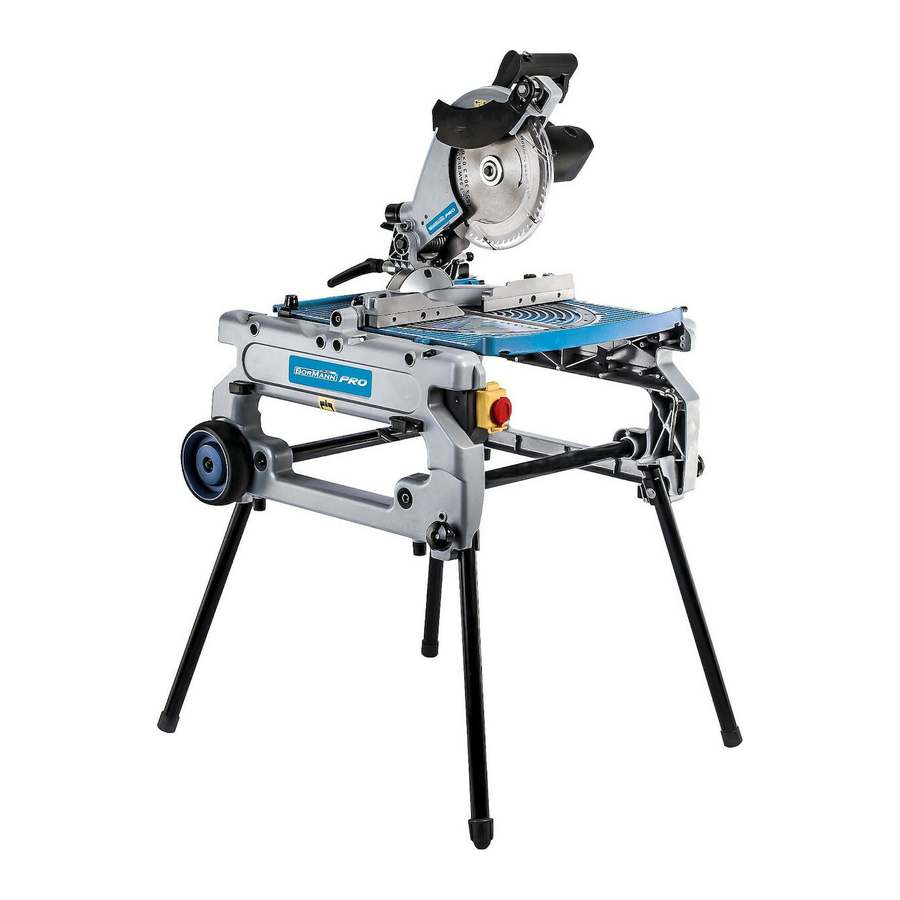
- Page 1 BFS1800| ΦΑΛΤΣΟΠΡΙΟΝΟ ΑΝΤΡΕΠΟΜΕΝΟ ΦΟΡΗΤΟ Owner’s manual Μετάφραση του πρωτοτύπου των οδηγιών χρήσης Art Nr: 022947 www.BormannTools.com...
- Page 2 www.BormannTools.com...
- Page 3 www.BormannTools.com...
- Page 4 www.BormannTools.com...
- Page 5 www.BormannTools.com...
- Page 6 www.BormannTools.com...
- Page 7 www.BormannTools.com...
- Page 8 www.BormannTools.com...
- Page 9 www.BormannTools.com...
- Page 10 www.BormannTools.com...
- Page 11 www.BormannTools.com...
- Page 12 www.BormannTools.com...
- Page 13 Technical Data Τεχνικά χαρακτηριστικά Voltage/Frequency: 230V-50HZ Τάση/Συχνότητα: 230V-50HZ Input power: 1800W Ισχύς: 1800W No load speed: 4200RPM Ταχύτητα χωρίς φορτίο: 4200RPM Blade size: O254MM Διαστάσεις λεπίδας: O254MM Max. cutting at 0 * 90 H65*W155MM Ικανότητα κοπής 0 * 90 H65*W155MM Max.
- Page 14 Symbols/Σύμβολα The following symbols can be found in the following pages and on the machine. Be sure that you understand their meaning before using the machine. Τα ακόλουθα σύμβολα εμφανίζονται στις σελίδες που ακολουθούν και επισημαίνουν πληροφορίες σημαντικές για την προστασία...
- Page 15 • Λόγω του συνεχούς προγράμματος έρευνας και ανάπτυξης, οι προδιαγραφές του παρόντος εγγράφου υπόκεινται σε αλλαγές χωρίς προειδοποίηση. • Σημείωση: Οι προδιαγραφές ενδέχεται να διαφοροποιούνται ανάλογα με το κράτος στο οποίο διατίθεται το προϊόν. Προβλεπόμενη χρήση Το εργαλείο προορίζεται για την ακριβής ευθεία και με κλίση κοπή σε ξύλο. Μπορεί να χρησιμοποιηθεί σαν φαλτσοπρίονο κοπής αλλά...
- Page 16 21. Πριν χρησιμοποιήσετε το εργαλείο σε ένα πραγματικό τεμάχιο εργασίας, αφήστε το να λειτουργήσει χωρίς φορτίο για λίγο. Ελέγξτε για ενδείξεις εμφάνισης κραδασμών ή παράκεντρη περιστροφή που μπορεί να υποδεικνύουν λανθασμένη τοποθέτηση ή ευθυγράμμιση του δίσκου κοπής. 22. Περιμένετε έως ότου ο δίσκος αναπτύξει την μέγιστη ταχύτητα περιστροφής πριν κόψετε κάποιο υλικό. 23.
- Page 17 ΦΥΛΑΞΤΕ ΤΙΣ ΟΔΗΓΙΕΣ ΣΕ ΕΝΑ ΑΣΦΑΛΕΣ ΣΗΜΕΙΟ ΕΓΚΑΤΑΣΤΑΣΗ ΠΡΟΣΟΧΗ: • Διατηρήστε την περιοχή του δαπέδου γύρω από τον χώρο τοποθέτησης του εργαλείου τακτοποιημένο και καθαρό. Τοποθέτηση σε πάγκο εργασίας (Σχήματα 1, 2 & 3) Για την εγκατάσταση με πλήρως επεκταμένα τα πόδια όταν δεν μπορούν να ρυθμιστούν σταθερά. Γυρίστε το παξιμάδι ρύθμισης στο...
- Page 18 Διατηρώντας τη μέγιστη ικανότητα κοπής (Εικ. 7) Αυτό το εργαλείο έχει ρυθμιστεί εργοστασιακά ώστε να παρέχει τη μέγιστη ικανότητα κοπής του. Κατά την εγκατάσταση ενός νέου δίσκου κοπής ελέγχετε πάντα το κάτω όριο του δίσκου κοπής και ρυθμίστε εφόσον χρειάζεται ως...
- Page 19 Απελευθερώστε το μοχλό του διακόπτη για να σταματήσετε την διαδικασία. Ενεργοποιήστε το εργαλείο για τη λειτουργία ως φαλτσοπρίονο. ΠΡΟΣΟΧΗ: • Πριν από τη λειτουργία, βεβαιωθείτε ότι το εργαλείο είναι ενεργοποιημένο και απενεργοποιημένο. Για να ξεκινήσετε το εργαλείο, πατήστε το κουμπί ON (I). Για να το σταματήσετε, πατήστε το πλήκτρο OFF. Ρύθμιση...
- Page 20 Τοποθέτηση ή αφαίρεση του δίσκου κοπής ΠΡΟΣΟΧΗ: • Να είστε πάντα βέβαιοι ότι το εργαλείο είναι απενεργοποιημένο και αποσυνδεμένο πριν συνδέσετε ή αφαιρέσετε τον δίσκο κοπής. • Χρησιμοποιήστε μόνο το παρεχόμενο κλειδί για την τοποθέτηση ή την αφαίρεση του δίσκου. Εάν δεν το κάνετε, μπορεί να προκαλέσετε...
- Page 21 τεμάχιο που βρίσκεται μεταξύ του δίσκου και του οδηγού το οποίο πολλές φορές εκσφενδονίζεται προς τα έξω προς το μέρος του χειριστή. Η γραμμή (A) διαφέρει ανάλογα με το πάχος του τεμαχίου εργασίας ή το επίπεδο του τραπεζιού. Ρυθμίστε τη θέση του...
- Page 22 Σταθεροποιήστε το τεμάχιο εργασίας ΠΡΟΕΙΔΟΠΟΙΗΣΗ Είναι εξαιρετικά σημαντικό να σταθεροποιείτε πάντα το τεμάχιο εργασίας σωστά με ασφάλεια στη μέγγενη. Εάν δεν το κάνετε, μπορεί να προκληθεί ζημιά στο εργαλείο ή / και στο τεμάχιο εργασίας. Μπορεί να προκληθεί σοβαρός τραυματισμός. Επίσης, μετά...
- Page 23 ΠΡΟΣΟΧΗ: • Όταν η κεφαλή του εργαλείου δεν μπορεί να ασφαλιστεί στην πλήρως χαμηλωμένη θέση, περιστρέψτε το μοχλό ρύθμισης βάθους πολλές στροφές δεξιόστροφα. (Εικ. 47) • Πριν γυρίσετε ανάποδα το εργαλείο, βεβαιωθείτε πάντοτε ότι ο πείρος έχει ασφαλίσει καλά την κεφαλή του εργαλείου στη χαμηλότερη...
- Page 24 Διαστάσεις τεμαχίου εργασίας (Υ x Π) Ανάγκη τοποθέτησης των δευτερευόντων προφυλακτήρων 68 mm x 155 mm ΝΑΙ 20 mm x 210 mm ΟΧΙ ΛΕΙΤΟΥΡΓΙΑ ΠΡΟΣΟΧΗ: Πριν από τη χρήση, βεβαιωθείτε ότι έχετε απελευθερώσει τη λαβή από τη χαμηλωμένη θέση τραβώντας τον πείρο του αναστολέα...
- Page 25 Για την εκτέλεση σύνθετης κοπής ανατρέξτε στα κεφάλαια όπου περιγράφονται τα δύο είδη κοπής ξεχωριστά. 1. Κοπή προφίλ αλουμινίου (Εικ. 56) Κατά τη στερέωση των τεμαχίων αλουμινίου, χρησιμοποιήστε διαχωριστικά μπλοκ ξύλου ή ρετάλια ξύλου όπως φαίνεται στο σχήμα για την αποφυγή παραμόρφωσης του αλουμινίου. Χρησιμοποιήστε ένα λιπαντικό κοπής όταν κόβετε τεμάχια αλουμινίου για...
- Page 26 Τροφοδοτήστε το τεμάχιο με το χέρι μέχρι το άκρο να είναι περίπου 25 mm από την μεταλλική άκρη της επιφάνειας του τραπεζιού. Συνεχίστε να τροφοδοτείτε χρησιμοποιώντας το μπλοκ ώθησης στο επάνω μέρος του βοηθητικού οδηγού μέχρι να ολοκληρωθεί η κοπή. (Σχήμα 62) Εγκάρσια...
- Page 27 Γωνία φάλτσου 1. Γωνία φάλτσου 0 Χαμηλώστε πλήρως την κεφαλή και ασφαλίστε την τραβώντας και περιστρέφοντας τον πείρο ασφάλισης 90 μοίρες δεξιόστροφα. Χαλαρώστε το μοχλό στο πίσω μέρος του εργαλείου. Γυρίστε στην κάτω μεριά του τραπεζιού, τον κοχλία ρύθμισης της γωνίας κλίσης 0 ° στη δεξιά πλευρά του κάτω βραχίονα δυο ή τρεις...
-
Page 28: Additional Safety Rules For Tool
• Due to our continuing program of research and development, the specifications herein are subject to change without notice. • Note: Specifications may deter train country to country. Intended use The tool is intended for accurate straight and miter cutting in wood. The tool can be used both in miter saw mode and in table saw mode by turning over the table around its axis. -
Page 29: Installation Caution
28. Some dust created from operation contains chemicals known to cause cancer, birth defects or other reproductive harm. Some examples of these chemicals are: Lead from lead-based-painted material. Arsenic and chromium from chemically-treated lumber. Your risk from these exposures varies, depending on how often you do this type of work. To reduce your exposure to these Chemicals: work in a well ventilated area and work with approved safety equipment, such as those dust masks that are specially designed to filter out microscopic particles. - Page 30 When lowering the handle while pushing the lever to the left, the lower blade guard A rises automatically. The lower blade guard B rises as It contacts a workpiece. The lower blade guards are spring loaded so it returns to its original position when the cut is completed and the handle is raised.
- Page 31 CAUTION: • When tilting the saw blade, be sure to raise the handle fully. • Alter changing the bevel angle, always secure the arm by tightening the lever clockwise. In the table saw mode (Fig. 13) To adjust the bevel angle, loosen the lever under the table at the front of the tool counterclockwise. Move the depth adjusting knob to the left to tilt the saw blade until the pointer points to the desired angle on the bevel scale.
- Page 32 Low table set up (Fig. 19) 1. The feet can be bolded as shown in the figure. To fold down the tool, do as follows_ 2. Fall down the tool carefully BACKWARDS without tail while holding it with both hands. 3.
- Page 33 Installing and adjusting rip fence (Fig. 28) 1. Install the rip fence on the table so that the rip fence holder engages with the guide rail. Tighten the clamping screw (B) on the rip Fence firmly clockwise_ 2. Loosen the clamping screw (A) 3.
- Page 34 Securing workpiece WARNING It is extremely important to always secure the work-piece properly and tightly with the vise. Failure to do so can cause the tool to be damaged and/or the work-piece to be destroyed. PERSONAL INJURY MAY ALSO RESULT. Also, after a cutting operation, DO NOT raise the blade until the blade has come to a complete stop.
- Page 35 Turning over the tool (Fig. 48) WARNING • Make sure that the tool is switched off and unplugged before turning over. • When pushing down the lever, be sure to place your hand finger away from the lever-table fitting area. Hold the middle edge of table with one hand, push the lever down with the other hand while holding the table edge firmly and pivot the table carefully to turn it over Keep holding it until it locks 8.
- Page 36 CAUTION: • Do not apply excessive pressure on the handle when cutting. Too much force may result in overload of the motor and/or decreased cutting efficiency. Push down handle with only as much force as is necessary for smooth cutting and without significant decrease in blade speed.
- Page 37 Always use 'work helpers' such as push sticks and push blocks when cutting small or narrow workplaces, or when the ado head is hidden from view while cutting. Work helpers (optional) Push sticks, push blocks or auxiliary fence are types of "work helpers" Use them to make safe and sure cuts without the need for the operator to contact the blade with any pan of the body.
- Page 38 Carry the tool by holding the tool part shown in the figure. (Fig. 67) CAUTION Always secure all moving portions before carrying the tool. • Before carrying the tool, always set up the tool in the miter saw mode. • Make sure that the lower blade guard C is installed on the tool.
Need help?
Do you have a question about the PRO BFS1800 and is the answer not in the manual?
Questions and answers