
Related Manuals for GRAPHTEC F-Mark 2


Summary of Contents for GRAPHTEC F-Mark 2
- Page 1 Setup userʼs manual F-Mark2 setup userʼs manual_01E Read this manual carefully before using the machine. Keep the manual in a handy place for future reference.
-
Page 2: Table Of Contents
CONTENTS Safety Precautions ..............1 Terms of use for F-Mark2 ..............2 3. Necessary items in advice for installing F-Mark2 ......3 4. Main Specifications ..............4 5. External Dimensions ..............5 6. How to unpack the box of F-Mark2 ..........6 7. Confirm the accessories of F-Mark2 ..........12 8. -
Page 3: Safety Precautions
1. Safety Precautions Indicates a potentially hazardous situation if not avoided, could result in death or serious injuries. Following these guidelines to avoid to the risk of fire, burns, injury, electro shocks, rupture, overheating, abnormal odors or smoke. Always use the recommended AC adapter (EA10682U-120 from EDAC Power) for the F-Mark ... -
Page 4: Terms Of Use For F-Mark2
2. Terms of use for F-Mark2 Restriction on use F-Mark2 F-Mark2 cannot be connected with other cutting plotter. F-Mark2 cannot be use with Plug-in software and Graphtec Design software with accessories of CE7000. F-Mark2 cannot be use with “Simple Mode” of CE7000. -
Page 5: Necessary Items In Advice For Installing F-Mark2
3. Necessary items in advance for installing F-Mark2 Please prepare the working table of the following size as installation place of F-Mark2. The required space is 800 mm or more in width, 820 mm or more in length, 420 mm or more ... -
Page 6: Main Specifications
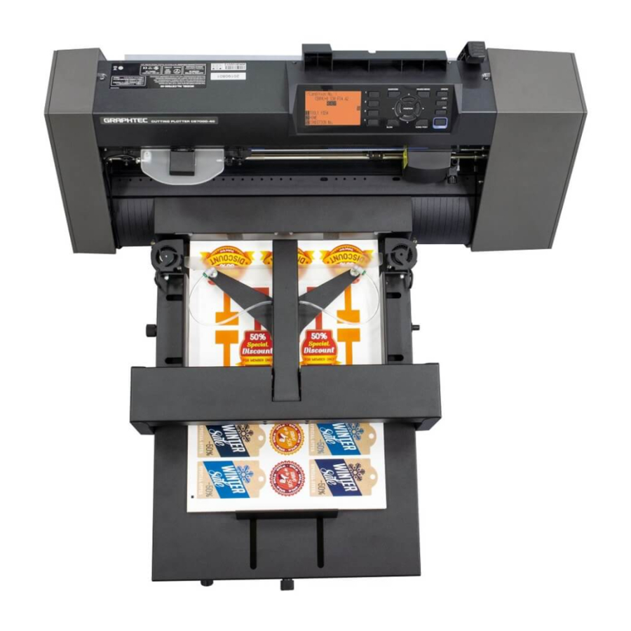
4. Main Specifications The F-Mark2 automatic feeder is part of the CE7000 ASF(Auto Sheet Feeder) system. It allows automatic operations for contour cutting on printed adhesive sheets or cardboard. The system is composed by an automatic feeder, a cutting plotter, a dedicated software with optical detection features and Exit Tray. -
Page 7: External Dimensions
5. External Dimensions The tabletop length required to connect and install the F-Mark2 to the cutting plotter is 820 mm. The width of F-Mark2 when connected to the CE7000-40 is 772 mm. When F-Mark2 connecting to the CE7000-40, 50 mm space is required on each side of the ... -
Page 8: How To Unpack The Box Of F-Mark2
6. How to unpack the box of F-Mark2 1. Open the box of the F-Mark2 with a knife. 2. Remove the packing material from the box. 3. Take out the Accessories box from the box. - 6 -... - Page 9 4. Take out the Exit tray from the box. 5. Remove the packing material from the box. 6. Remove the side packing materials from the box. - 7 -...
- Page 10 7. Remove the back side packing material from the box. 8. Take out the F-Mark2 from the box. 9. Take out the F-Mark2 from the packing plastic bag. - 8 -...
- Page 11 10. Peel off two Velcro which fixing the Arm cushioning material. 11. Detach the front Arm cushioning material from the F-Mark2. 12. Detach the rear Arm cushioning material from the F-Mark2. - 9 -...
- Page 12 13. Detach the two cushioning materials under the Arm from the F-Mark2. 14. Turn the Blower to the side. 15. Take out the Exit Tray from the packing plastic bag. - 10 -...
- Page 13 16. Take out the Test Cut sheets and Calibration sheets from the Exit Tray. There are 12 Test Cut sheets and 2 Calibration sheets. - 11 -...
-
Page 14: Confirm The Accessories Of F-Mark2
7. Confirm the accessories of F-Mark2 1. Open the accessories box with a knife. 2. Confirm the accessories of F-Mark2 with following lists. Quantity Item Image Camera assembly Allen wrench (2mm) for camera mounting Suction cup for spare AC power adapter for F-Mark Power cord for AC power adapter... - Page 15 Item Image Quantity USB Hub USB cable 1.0m from USB Hub to Cutting plotter Adhesive cable crip for camera cable fixing Alignment label For mounting position of F-Mark2 to CE7000-40 CD-Rom Safety Precautions Calibration sheet (Not in the accessories box) Test Cut sheet - 13 -...
- Page 16 Item Image Quantity Stopper Plate (Not in the accessories box) Tail Tool (Not in the accessories box) Exit Tray (Not in the accessories box) - 14 -...
-
Page 17: Names And Functions Of F-Mark2
8. Names and Functions of F-Mark2 Media Separation Flap Insertion Flap Blower Side Media Guide Media Supply Tray Side Media Guide Rear Media Guide Adjusting Knob Blowers Speed Adjustment knob Rear Media Guide Adjusting Knob Power Switch Media Separation Flap : For prevent media double feeding. ... - Page 18 Side view Suction Cups Vacuum Adjusting Knob Suction Cups : Pick up media by Suction Cups when inserting the media to the cutting plotter. Vacuum Adjusting Kob : Adjust the vacuum force to pick up media. When turning the knob clockwise, the vacuum force increasing. When turning the knob counterclockwise, the vacuum force decreasing.
-
Page 19: How To Install F-Mark2
9. How to install F-Mark2 1. Peel off the adhesive tape on the back of Exit tray. 2. Put the Exit tray on the working table. Then press the Exit tray firmly on the Working table. The adhesive tape fix the Exit tray for a short time, it may drop if you do not place the CE7000-40. - Page 20 4. Adjust the position the CE7000-40 so that the right edge of the Exit tray is align the 9th line of the Rear Cover of the CE7000-40, in order to media which after cut by the CE7000-40 drop into the Exit tray correctly. 5.
- Page 21 6. Connect the F-Mark2 to the CE7000-40 so that the front edge of the F-Mark2 fits into the groove on the Front Cover of the CE7000-40. - 19 -...
-
Page 22: How To Attach The Camera To Ce7000-40
10. How to attach the Camera to the CE7000-40 1. Detach the two M2L20 screws from the Camera Assembly using the accessory allen wrench. 2. Separate the Bracket from the Camera 3. Insert the Bracket into the back of Center Cover of the CE7000-40. 4. - Page 23 5. Align the Camera with the Bracket and attached it. When attach the camera to the Bracket, align the two ribs on the Camera with two grooves on the Bracket. 6. Attach the two M2L20 screws to the Bracket to fixing the Camera to the Center Cover of the CE7000-40.
- Page 24 7. Tighten the two M2L20 screws using the accessory allen wrench to fix the Camera to the CE7000-40. 8. Detach the Camera Lens Cover from the Camera. 9. Paste the two Adhesive cable crips to the left side inner wall of the CE7000-40. And then fix the Camera cable on the crips.
-
Page 25: Cable Connection
11. Cable connection Connect the USB cables and AC power cable to the F-Mark2 as shown picture below Bottom view AC power cable to the AC power adapter USB cable to the computer USB cable from the inside of the F-Mark2 USB cable to the CE7000 USB cable to the camera USB Hub... -
Page 26: How To Install The Imark Plus Software
12. How to install the iMark Plus software Please check the following items before installing the iMark Plus software into the computer. When there is virus detection programs and programs that reside in the system, please exit in advance. To install the software, login the Windows as a member of the administrator account ... - Page 27 3. Welcome to the i-Mark Install program window will be displayed. Click “Next >” button. 4. The window for selecting the compter directory to install the iMark Plus software will be displayed. Click the “Next >” button. NOTICE Do not change the folder that installing the iMark Plus software from the default settings (C:\Script).
- Page 28 6. iMark Plus software installing will be started. 7. When iMark Plus software installation is completed, the Microsoft Visual C++2012 installing window will be displayed. 8. Click the check box of “I agree to the license terms and conditions”, and then click the “Install” button to start the installing. - 26 -...
- Page 29 9. Microsoft Visual C++ 2012 installing will be started. 10. When installation is completed, click the “Close” button to close the window. 11. Click the “Exit” button to complete the installation. NOTICE iMark Puls software will not be launch if the F-Mark2 does not connected to the computer. ...
-
Page 30: Notice On Using The Imark Plus Software
13. Notice on using the iMark Plus software Please note the followings when using iMark Plus software on computer. When there is virus detection programs and programs that reside in the system, please exit in advance. Disable the “Sleep Mode” and “Power Saving Mode” and “Screen Saver” of the operation ... - Page 31 If operating the iMark Plus software with the setting of the camera privacy set to “Off” on a computer which installed Windows10, the iMark Plus software can not be launched, because the F-Mark2 camera can not be used. In that case, please change the setting of camera privacy in the following procedure. <<...
-
Page 32: How To Adjust The Angle Of The Camera
14. How to adjust the angle of the Camera 1. Launch the iMark Plus software. 2. Loosen the thumb screws on right side of the Camera to adjust the angle of the Camera. 3. Adjust the angle of the Camera so that the groove on the Front Cover of the CE7000 align to the reference lines that displayed in the iMark Plus software as show in picture below. - Page 33 4. Tighten the thumb screws while pay attention so that the angle of the Camera does not change. NOTICE After adjusting the angle of Camera, please operate the F-Mark2 so that the angle of Camera does not change. Before cutting media with F-Mark2 or performing the Calibration of the F-Mark2, ...
-
Page 34: How To Initialize F-Mark2 And Ce7000-40
15. How to initialize F-Mark2 and CE7000-40. Please check the following items before setting the F-Mark2 and CE7000-40. The iMark Plus software is installed in the operation computer. The F-Mark2 connected to the operation computer and CE7000-40. 1. Lower the Media Set Lever of the CE7000-40 to move the left side Push Roller position. 2. - Page 35 3. Turn on the CE7000-40, and select the language and unit displayed on the CE7000-40. NOTICE This setting is performed only at the initial setting of the CE7000-40. Displayed unit of the CE7000-40 and operating units of iMark Plus software are not linked. ...
- Page 36 5. Rise the Media Set Lever of the CE7000-40. 6. Press the “2” button on the control panel of the CE7000-40. Then the Tool Carriage will be moved between the left and right Push Rollers. After that, the “READY” will be displayed on the control panel of the CE7000-40. After Tool Carriage moving between the left and right Rush Rollers, the “READY”...
- Page 37 7. Launch the iMark Plus software on the operation computer. And click the “iMark icon” on the upper left in the iMark Plus software screen. 7. Pull down menu will be displayed, and then click the “About iMark...” to open the “About iMark” window.
- Page 38 9. When the settings of the CE7000-40 has been correctly changed to the F-Mark2, “1:Label Media” will be displayed on the control panel. Label Media 10. Click the “Close” button to finish the setting of CE7000-40. NOTICE This procedure needs to be performed under the following conditions in order to operate the F-Mark2 properly.
-
Page 39: How To Calibrate F-Mark2
16. How to calibrate F-Mark2 The F-Mark2 needs to be calibration in order to read the crop mark correctly. Please check the following items before performing the calibration of the F-Mark2. The iMark Plus software is installed in the operation computer. ... - Page 40 2. Rise the Media Set Lever of the CE7000-40, and then press the “2” button on the control panel of the CE7000-40. 3. Set the Cutter Plunger to the back side (for Half Cutting) of the Tool holder on the CE7000-40. Cutter Plunger Back side:...
- Page 41 3. Launch the iMark Puls software, and confirm that the “Enable” in the “Dashed line” is not checked, and then click the “Calibration button” NOTICE Calibration can not be performed correctly if “Enable” in the “Dashed line” is checked. 4. The “Calibration”window will be displayed, then click the “Cut Marker” button, and then the CE7000-40 will be cutting a small square on the Calibration Sheet.
- Page 42 5. Peel off a small square cut by the CE7000-40 from the Calibration Sheet so that the white square can be see. NOTICE If the cut square can not be peeled off well from the Calibration Sheet or if the cut square cut out from the Calibration Sheet, please adjust the following items.
- Page 43 6. Click the “Read Maker” button to read the calibration data, and then click the “Set” button to saving the calibration data. NOTICE When performing “Read Maker”. If the “Read Marker” is performed while the calibration sheet is reflecting by the Lighting in the room, the correct calibration may not be performed, in this case, please shade the camera unit so that the small square part is not reflected by the light, and then perform the “Read Maker”.
- Page 44 7. Click the “X” button on the upper left on the Calibration window to close it, and remove the calibration sheet from the CE7000-40 and finish the calibration. 8. After calibration is finished, perform the “Cut Test” to check the calibration of the F-Mar2 is correctly. NOTICE Two calibration sheets are included in the F-Mark2, if used up these, please print the ...
-
Page 45: How To Cut Test With Test Cut Sheet
17. How to cut test with Test Cut sheet Please check the following items before performing the cut test with Test Cut sheet. Prepare the Test Cut sheets that was included with the F-Mark2. The iMark Plus software is installed in the operation computer. ... - Page 46 2.Lower the Media Set Lever of the CE7000-40. 2. Pull out the tip of media to the front of Push Roller on the CE7000-40. And then shift the position of the F-Mark2 so that the crop mark on the Test Cut sheet under the Camera.
- Page 47 4. Shift the right side Push Roller according to the width of Test Cut sheet. NOTICE Never move the left side Push Roller position. 5. Remove the Test Cut sheet from the CE7000-40. 6. Rise the Media Set Lever of the CE7000-40, and then press the “2” button on the control panel of the CE7000-40.
- Page 48 7. Click “File Open” button to load the cut data file (multiple_labels test contour 32x45.ai) for the Test Cut sheet into the iMark Plus software. The cut data file (multiple_labels test contour 32x45.ai) for the Test Cut sheet is included in the F-Mark2 accessory CD.
- Page 49 9. Make sure that the “Cutter ready” is displayed on the bottom of the iMark Plus software window, and then click the “Cut Test” button to perform the cut test to the Test Cut sheet. - 47 -...
-
Page 50: How To Adjust The Cutting Position
18. Adjustment of cutting position After performing the test cut with Test Cut sheet, perform the adjustment of the cutting position. Adjustment of cutting position in X direction. Adjustment of cutting position in X direction can be adjusting by inputting the values in the bottom of camera preview window in the iMark Plus software. - Page 51 E.g. When cutting position is shifted as shown below drawing. Printed line Cutting line Feeding direction In such case, 1. Input “-20” into the X, and input “20” into the Y. 2. And then click the “Cut Test” button to perform the Cut Test, and confirm the cutting position. NOTICE The inputted values for X and Y will not be effective for the cutting position without ...
-
Page 52: Notice On Loading Media Into F-Mark2
19. Notice on loading media into F-Mark2 When loading the media into the F-Mark2, follow the procedure below. 1. Loading media into the Media Supply Tray on F-Mark2. 2. Adjust the position of Side Media Guide depending on the width of media to be used. (When adjusting the position of Side Media Guide, adjust the position so that the Side Media Guide lightly touches to the side of media to be used.) Side Media Guide... - Page 53 5. Push the front edge of media into the Media Supply Tray. 4. When using Blowers, adjust the rotation speed of Blowers and the width of Side Media Guide So that the media slightly rises. Blowers Blowers Speed Adjusting Knob - 51 -...
-
Page 54: How To Use Stopper Plate
20. How to use Stopper Plate If correctly cut can not be performed due to the front edge of media that being cut with CE7000 interferes with media in the Exit Tray, might be able to solve the problem by attaching the Stopper Plate on the Exit Tray. -
Page 55: How To Use Tail Tool
21. How to use Tail Tool When the Tail Tool is attached to the rear part of CE7000-40, the media that after cutting with CE7000-40 will be fit into the Exit Tray without scattering. Attach the Tail Tool to the rear part of the CE7000-40 as shown as picture below. ... -
Page 56: How To Attach The Extension Plate
22. How to attach the Extension Plate (It is sold separately) When attach the “Extension Plate” to F-Mark2, the media of length 500 mm to 700 mm can be use in F-Mark2. NOTICE The “Extension Plate” is not included in accessories of F-Mark2. It si sold separately. ... - Page 57 4. Attach the Extension Plate to F-Mark2. Extension Plate 3. Fix the Extension Plate to F-Mark2 with two M4L10 allen screws using the 2.5mm allen wrench. M4L10 allen screw Extension Plate - 55 -...
-
Page 58: How To Replace The Suction Cups And Insertion Flap
23. How to replace the Suction Cups and the Insertion Flap ● Two Suction Cups are included in the accessories of F-Mark2 for initial replacement. ● Insertion Flap is not included in the accessories of F-Mark2, please purchase it for replacement. Suction Cups If F-Mark2 can not pick up media correctly, replace the Suction Cups. - Page 59 2. Replace the Insertion Flap if necessary. Insertion Flap 3. Insert the Insertion Flap into the suction cups connection part where located on the front edge of the Arm and then insert the Suction Cups. When inserting the Suction Cups, insert the Suction Cups while rotating it so that the Suction Cups are firmly inserted until end of connection part while holding the Arm.
-
Page 60: Troubleshooting
24. Troubleshooting 1. The Arm does not perform the initial operation even if turn on F-Mark2. Symptom Check items Solutions Check that the connection of the Check that the green light on the AC power adapter and power cord power switch is on. connected correctly. - Page 61 2. When click the “Cut Test” or “Start” button in the iMark Plus software, the message “F-Mark feeder off or not connected software protection not connected” will be displayed on the operated computer and F-Mark2 does not work. Symptom Check items Solutions Refer to “The Arm does not Check that the F-Mark2 power is...
- Page 62 3. Troubleshooting for other symptoms Symptom Check items Solutions Connect CE7000-40 to USB-Hub CE7000-40 is not connected to with USB cable, and initialize USB-Hub of F-Mark2 with USB CE7000-40. cable. Refer to “How to initialize The “Calibration” button in iMark F-Mark2 and CE7000-40.”...
- Page 63 Symptom Check items Solutions The USB cable of the camera is Check that the USB cable of not connected securely. camera is connected correctly. If the external camera is connected,disconnect the camera other than F-Mark2 camera from the operation The camera other than F-Mark2 computer.
- Page 64 Symptom Check items Solutions Turn the “Vacuum Adjusting There is not enough vacuum Knob” to clockwise to increase force to lift the media. the vacuum force. The surface of Suction Cups are Clean the surface of Suction Cups dirty. where contact with the media. When lifting the media from the Replace the Suction Cups if they Media Supply Tray, the media will...
- Page 65 Symptom Check items Solutions Changes temperature or The media has been curled or humidity might be cause the shrank in the unstable operating media curled or shrunk. environment. Use F-Mark2 in the stable operating environment. Sometimes, F-Mark2 can not be The media can not be pick up one Remove the static electricity from insert the media to the...
Need help?
Do you have a question about the F-Mark 2 and is the answer not in the manual?
Questions and answers