
Subscribe to Our Youtube Channel
Related Manuals for COMAC ULTRA 120 B-G


Summary of Contents for COMAC ULTRA 120 B-G
- Page 1 ULTRA 120 B-G SCRUBBING MACHINES USE AND MAINTENANCE MANUAL ORIGINAL INSTRUCTION DOC. 10029463 - Ver. AC - 04-2016...
-
Page 3: Table Of Contents
CONTENTS CONTENTS ..............................3 SYMBOLS USED IN THE MANUAL ....................... 5 MAIN MACHINE COMPONENTS ........................6 PURPOSE AND CONTENT OF THE MANUAL .................... 11 TARGET GROUP ............................11 STORING THE USE AND MAINTENANCE MANUAL .................. 11 ON CONSIGNMENT OF THE MACHINE ...................... 11 INTRODUCTORY COMMENT ........................ - Page 4 WORK ................................41 SWITCHING ON THE MACHINE (B VERSION) ........................41 SWITCHING ON THE MACHINE (G VERSION) ........................41 WORK .......................................42 BATTERY CHARGE LEVEL ..............................43 SELECTING THE OPERATING DIRECTION ...........................44 ADJUSTING THE OPERATING SPEED ..........................44 ADJUSTING THE PRESSURE ON THE BRUSHES ........................44 SIDEWAYS MOVEMENT OF THE BRUSH HEAD UNIT ......................44 ADJUSTING THE SUPPLY OF DETERGENT SOLUTION ......................45 DIPPED HEADLIGHTS ................................46...
-
Page 5: Symbols Used In The Manual
The descriptions contained in this document are not binding. The company therefore reserves the right to make any modifications at any time to elements, details, or accessory supply, as considered necessary for reasons of improvement or manufacturing/commercial requirements. The reproduction, even partial, of the text and drawings contained in this document is prohibited by law. The company reserves the right to make any technical and/or supply modifications. -
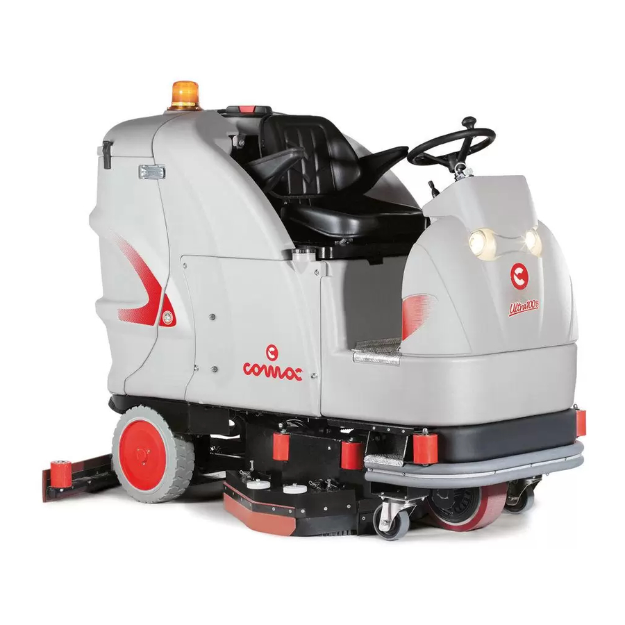
Page 6: Main Machine Components
MAIN MACHINE COMPONENTS The front components of the machine are: Gasoline bypass tap (G version) Detergent solution bypass tap (CDS version) Filter retainer ring on vacuum cap Detergent solution filter tap Starter battery (G version) Operator seat Squeegee unit vacuum nozzle Gasoline tank (G version) Side splash guard vacuum nozzle Detergent tank (CDS version) -
Page 11: Purpose And Content Of The Manual
PURPOSE AND CONTENT OF THE MANUAL The aim of this manual is to provide customers with all the information needed to use the machine in the safest, most appropriate and most autonomous way. This includes information concerning technical aspects, safety, operation, downtime, maintenance, spare parts and scrapping. -
Page 12: Technical Data
ULTRA ULTRA 120 ULTRA 120 TECHNICAL DATA 120 B G bi-fuel G gasoline Rated machine power 5355 Working capacity up to 9600 Working width 1205 Squeegee width 1265 Brushes on brush head (number / Ø external bristles) No. / mm 2 / 610 Rpm of the single brush on the brush head Brush head engine (voltage / rated power) - Page 13 ULTRA ULTRA 120 ULTRA 120 TECHNICAL DATA 120 B G bi-fuel G gasoline Machine weight 1050 1039 Machine weight in transport mode 1275 1050 1039 Machine weight in working mode 1685 1366 1332 Maximum weight of the battery box (recommended) (B versions) Maximum weight of the recommended cylinder (tare weight + LPG) (G bi-fuel versions) Sound pressure level (ISO 11201) - L pA...
-
Page 14: General Safety Regulations
GENERAL SAFETY REGULATIONS The following regulations below must be carefully respected to avoid harm to the operator and damage to the machine. WARNING: • Read the labels on the machine carefully. Do not cover them for any reason, and replace them immediately if they become damaged. - Page 15 • In the event of a hazardous situation, quickly remove the battery connector from the main system connector (both are located beneath the seat mounting plate) (B versions). • In the event of a hazardous situation, quickly remove the alternator connector from the main system connector (both are located beneath the seat mounting plate) (G versions).
- Page 16 • The machine must only be powered with a voltage equal to that shown on the serial number plate. (B versions). • If the machine is left unattended, it must be protected from any accidental movements. • The machine must be regularly inspected by a qualified person, especially with regards the LPG tank and its connections, as required by local or national safety regulations.
- Page 17 handling the fuel, to avoid any risk of serious injury to your hands. • For the characteristics of the recommended fuel, refer to the Use and Maintenance Manual of the endothermic engine. • Gasoline is highly and easily flammable. Keep away from fires and do not shake fuel containers.
- Page 18 ATTENTION: • The machine must not be used or stored outdoors in damp conditions or directly exposed to rain. • The appliance must be stored in a closed area with a temperature between -25°C and +55°C. • Conditions of use: room temperature between 0°C and 40°C, with relative humidity between 30 and 95%.
- Page 19 helmet, goggles, etc.). • If the machine does not work properly, check this is not caused by failure to carry out routine maintenance. Otherwise, ask for intervention of the authorised technical assistance centre. • If you need to replace any components, request the ORIGINAL spare parts from an Authorised Retailer or dealer.
-
Page 20: Symbols Used On The Machine
SYMBOLS USED ON THE MACHINE Solution tank drainage tube label: Located on the rear part of the machine, to identify the solution tank drainage tube. Recovery tank drainage tube label: Located on the rear part of the machine, to identify the recovery tank drainage tube. Parking brake lever label: Located near the operator seat, to identify the command lever of the parking brake. - Page 21 Label about detergent solution filter cleaning: Located on the front left-hand side of the machine, to identify the position of the detergent solution filter and remind the operator to clean it after every machine use. Treading ban label: Located on the machine, to identify the surfaces that must not be trodden on (risk of personal injury or damage to the machine).
- Page 22 Label indicating that it is forbidden to use water to put out fires (G versions): Located near the gasoline tank, to indicate that it is forbidden to put out fires with water. Label indicating the danger of highly flammable compressed gas (G versions): Located above the cylinder support, to indicate the presence of highly flammable compressed gas.
-
Page 23: Symbols Used On The Control Panel
SYMBOLS USED ON THE CONTROL PANEL Buzzer symbol: Indicates the buzzer command button. Confirmation button symbol: Indicates the command display confirmation button. i-drive selector symbol: Indicates the command knob for the i-drive program selector. Direction selector symbol: Indicates the lever for selecting the machine movement direction. Movement speed selector symbol: Indicates the knob for selecting the machine movement speed. -
Page 24: Symbols Used On The Serial Number Plate
Symbol of indicator light for engaged parking brake: Indicates the red indicator light. The indicator light tells the operator to be careful because the parking brake is engaged. Symbol of indicator light for insufficient solution tank liquid: Indicates the red indicator light. The indicator light tells the operator to be careful because the level of liquid in the solution tank is below the minimum notch. -
Page 25: Machine Preparation
MACHINE PREPARATION HANDLING THE PACKAGED MACHINE The overall weight of the machine with its packaging is: • 885kg - B version (weight of unladen machine with packaging) • 1175kg - G bi-fuel version (weight of unladen machine with packaging) • 1165kg - G gasoline version (weight of unladen machine with packaging) The packaging dimensions are as follows:... -
Page 26: Taking The Machine Out Of Its Packaging (G Versions)
12. Select the speed level “step-01” and turn the knob (8) anti- 14. Release the parking brake by moving the parking brake lever clockwise until it reaches the bottom of the scale (Fig.10). (10) (at the side of the operator seat) in the direction shown by 13. - Page 27 9. Connect the alternator connector (5) to the general system 13. Grip the handle (4) at the side of the seat (Fig.3), and raise the connector (6) of the machine (Fig.5). seat mounting plate to the maintenance position (Fig.4). 10. Make sure the fuel tap (7) is closed. If it isn't, move the lever (8) 14.
-
Page 28: Transporting The Machine (B Versions)
23. Select the speed level “step-01” and turn the knob (13) anti- 28. Engage the parking brake by moving the parking brake lever clockwise until it reaches the bottom of the scale (Fig.17). (15) (at the side of the operator seat) in the direction shown by 24. -
Page 29: Transporting The Machine (G Versions)
ATTENTION: during this operation, check there are no people 11. Bring the main switch (1) to "0", turning the key (2) a quarter turn to the right ( Fig.10). Remove the key from the instrument panel. or objects near the machine. 12. - Page 30 6. When the engine starts up, release the engine switch and let it shown by the arrow until it reaches the “OPEN” position return to ON. (Fig.6). 7. Bring the command lever for the endothermic engine (1) rpm to its maximum - gradually shift the lever in the direction shown by 8.
-
Page 31: Type Of Battery To Be Used (B Versions)
18. Close the fuel tap (13) by moving the lever (14) in the direction ATTENTION: secure the device according to the directives in shown by the arrow (Fig.18). force in the country of use, so that it cannot slide or tip over. 19. - Page 32 6. Get off the machine. the maintenance position (Fig.6). 8. Disconnect the battery connector (7) from the main system ATTENTION: do not position your foot above the brush head connector (8) of the machine (Fig.7). while the machine is coming down the ramp. 9.
-
Page 33: Inserting The Batteries In The Machine (B Versions)
INSERTING THE BATTERIES IN THE MACHINE (B VERSIONS) The batteries must be housed in the specific compartment beneath ATTENTION: the equipment to be used for this operation is the seat support, and should be handled using lifting equipment that not supplied with the machine. is suitable both for the weight and for the coupling system. -
Page 34: Inserting The Starter Battery (G Version)
ATTENTION: after replacing the cylinder, carry out a seal test on the connections using soapy water (never use flames for ATTENTION: Comac S.p.A. recommends the use of standard this purpose) before attempting to switch on the machine. European 10kg cylinders with Ø30cm and height 60cm. -
Page 35: Filling The Gasoline Tank (G Versions)
FILLING THE GASOLINE TANK (G VERSIONS) To fill the gasoline tank, proceed as follows: 2. Make sure the machine is in a safe condition (read “MACHINE SAFETY”). 1. Bring the machine to the refuelling area. 3. Grip the handle (1) at the side of the seat (Fig.1), and raise the seat mounting plate to the maintenance position (Fig.2). -
Page 36: Assembling The Brush
ASSEMBLING THE BRUSH To assemble the brushes to bush head unit, which for reasons of 2. Engage the parking brake by moving the parking brake lever (1) packaging are supplied dismantled from the machine, proceed as (at the side of the operator seat) in the direction shown by the follows: arrow (Fig.1). -
Page 37: Assembling The Squeegee
ASSEMBLING THE SQUEEGEE For reasons of packaging, the squeegee is supplied dismantled 2. Engage the parking brake by moving the parking brake lever (1) from the machine. To fit it on the side bars, proceed as follows: (at the side of the operator seat) in the direction shown by the arrow (Fig.1). -
Page 38: Detergent Solution (Version Without Cds)
DETERGENT SOLUTION (VERSION WITHOUT CDS) After filling the solution tank with clean water add the liquid ATTENTION: always use detergents whose manufacturer's detergent to the tank in the concentration and manner indicated on label indicates their suitability for scrubbing machines. Do not the detergent manufacturer's label. -
Page 39: Preparing To Work
PREPARING TO WORK Before beginning to work, it is necessary to: 4. Check that the splash guard rubbers on the brush head are in good working condition. If this is not the case, replace them (see 1. Make sure the recovery tank is empty. If this is not the case, “REPLACING THE BRUSH HEAD SPLASH GUARD RUBBER”). -
Page 40: Triggering The Hydraulic System
TRIGGERING THE HYDRAULIC SYSTEM Before starting to work for the first time, or after a long period of 3. Engage the parking brake by moving the parking brake lever (3) machine inactivity, it is necessary to proceed as follows: (at the side of the operator seat) in the direction shown by the arrow (Fig.2). -
Page 41: Work
ATTENTION: the bottom line shows the hours and minutes of operation. The flashing “:” symbol Indicates that the hour ATTENTION: to display a different type of hour meter (e.g. meter is counting the machine functioning time. partial), contact specialised or COMAC-trained personnel. battery Total Serv.nev... -
Page 42: Work
ATTENTION: do not use the starter for more than 5 seconds 7. Bring the command lever for the endothermic engine (1) rpm to its maximum - gradually shift the lever in the direction shown by at a time. If the engine does not start up, release the key and wait for 10 seconds before making a new attempt. -
Page 43: Battery Charge Level
If the drive pedal is released while working and so the machine If the indicator light for a low liquid level in the solution tank (9) comes stops, the brush motors and the solenoid valve will be deactivated. on while you are working (Fig.9), stop the machine and top up the The squeegee unit will remain in contact with the floor. -
Page 44: Selecting The Operating Direction
SELECTING THE OPERATING DIRECTION The machine has a lever system for selecting the operating ATTENTION: move the lever in the direction shown by the direction (4). It is located on the control panel (Fig.1). arrow (Fig.3) to select reverse movement. ATTENTION: move the lever in the direction shown by the ATTENTION: move the lever to the middle (Fig.4) to select arrow (Fig.2) to select forward movement. -
Page 45: Adjusting The Supply Of Detergent Solution
ADJUSTING THE SUPPLY OF DETERGENT SOLUTION If your machine has no CDS system and you need to alter the ATTENTION: rotate the lever (2) in the direction shown by supply of detergent solution to the brushes while you are working, the arrow (Fig.3) to reduce the amount of solution. -
Page 46: Dipped Headlights
(20) by pressing it downwards (Fig.1). ATTENTION: if there is no oil in the braking system, the red indicator light (21) will be activated on the control panel (Fig.3). If this happens, contact a specialised Comac technician as quickly as possible. BUZZER The machine is equipped with a buzzer. -
Page 47: Solution Tank Float
SOLUTION TANK FLOAT The machine is fitted with an electronic device (float) located inside all the liquid in the vacuum tube to be suctioned off. the solution tank. When the tank is empty, it activates the solution 2. Bring the machine to the maintenance area and fill the solution tank float indicator light (9) on the command display (Fig.1). -
Page 48: At The End Of The Work
AT THE END OF THE WORK At the end of the work, and before carrying out any type of 3. As soon as the machine has reached the maintenance area, maintenance, perform the following operations: carry out the daily maintenance tasks indicated in the table in “RECOMMENDED MAINTENANCE WORK”... - Page 49 13. Grip the handle (2) and raise the seat mounting plate to the working position (Fig.4). maintenance position (Fig.3). 18. For machine versions with an endothermic engine powered with 14. Disconnect the battery connector (3) from the main system LPG, when parking the machine remember to close the cylinder connector (4) of the machine (Fig.9A - B versions).
-
Page 50: Recommended Maintenance Operations
RECOMMENDED MAINTENANCE OPERATIONS TYPE OF MAINTENANCE RECHARGING THE BATTERIES (1) DRAINING THE RECOVERY TANK CLEANING THE SQUEEGEE UNIT CLEANING THE BRUSHES CLEANING THE VACUUM MOTOR FILTER DRAINING THE SOLUTION TANK CLEANING THE SOLUTION TANK CLEANING THE WATER SYSTEM FILTER CLEANING THE VACUUM TUBE CLEANING THE BRUSH HEAD SPLASH GUARD RUBBERS CLEANING THE DETERGENT CANISTER (VERSIONS WITH CDS) CLEANING THE WATER SYSTEM... -
Page 51: Cleaning The Squeegee Unit
CLEANING THE SQUEEGEE UNIT Careful cleaning of the squeegee unit guarantees better cleaning and 4. Stand behind the machine. drying of the floor as well as a longer vacuum motor life. 5. Remove the squeegee vacuum tube (1) from the nozzle (2) on To carry out the cleaning of the squeegee unit, proceed as follows: the squeegee unit (Fig.2). -
Page 52: Cleaning The Disc Brushes
CLEANING THE DISC BRUSHES Careful cleaning of the disc brush guarantees better cleaning of the 5. Remove the pins (4) that block the rotation pins (5) of the brush floor as well as a longer brush motor life. head splash guard (Fig.3). To clean the disc brush, proceed as follows: 6. -
Page 53: Cleaning The Vacuum Motor Filter
CLEANING THE VACUUM MOTOR FILTER Careful cleaning of the vacuum motor filter guarantees a better dirty 3. Make sure the machine is in a safe condition (read “MACHINE water vacuuming capacity as well as a longer vacuum motor life. SAFETY”). To clean the vacuum motor filter, proceed as follows: ATTENTION: users are advised to always wear protective 1. -
Page 54: Cleaning The Recovery Tank
CLEANING THE RECOVERY TANK To clean the recovery tank, proceed as follows: 4. Release the recovery tank drainage tube (at the back of the machine) from the retainers. Remove the cap and place it on the 1. Select the i-drive program “transport” by rotating the knob to ground. -
Page 55: Cleaning The Detergent Solution Filter
CLEANING THE DETERGENT SOLUTION FILTER Careful cleaning of the detergent solution filter guarantees better ATTENTION: users are advised to always wear protective cleaning of the floor. gloves, to avoid the risk of serious injury to hands. Proceed as follows to clean the detergent solution filter: 4. -
Page 56: Cleaning The Brush Head Splash Guard
CLEANING THE BRUSH HEAD SPLASH GUARD Careful cleaning of the side splash guard rubbers of the brush head 4. Stand on the right side of the machine. Disconnect the side guarantees better cleaning of the floor. splash guard vacuum tube (1) from the vacuum nozzle (2) on To clean the side splash guard rubbers of the brush head, proceed the splash guard itself (Fig.2). -
Page 57: Cleaning The Detergent Tank (Versions With Cds)
CLEANING THE DETERGENT TANK (VERSIONS WITH CDS) Careful cleaning of the detergent canister guarantees better 5. Disconnect the quick-connection rubber-holder (2) (located efficiency of the machine water system, and therefore better behind the side carter) (Fig.3), to avoid any risk of it breaking efficiency when cleaning the floor. -
Page 58: Cleaning The Water System (Version Without Cds)
CLEANING THE WATER SYSTEM (VERSION WITHOUT CDS) If the machine is to be left unused for a long time, perform the 5. Press the drive pedal (3) to activate the brush head and the following tasks: dosing system (Fig.4). 1. Select the i-drive program “transport” by rotating the knob (1) to ATTENTION: as soon as you press the drive pedal, the brush position “A”... -
Page 59: Maintenance Of The Endothermic Engine (G Versions)
10. Check the water tap is fully open - the lever (5) must be turned ATTENTION: as soon as you press the drive pedal, the brush completely clockwise (Fig.5). head and squeegee unit will move down until they are in 11. -
Page 60: Extraordinary Maintenance Work
EXTRAORDINARY MAINTENANCE WORK REPLACING THE BRUSH The brush's integrity ensures better floor cleaning, as well as a longer 4. Stand on the right side of the machine. Disconnect the side brush motor life span. splash guard vacuum tube (1) from the vacuum nozzle (2) on To replace the brush, proceed as follows: the splash guard itself (Fig.2). -
Page 61: Replacing The Brush Head Splash Guard Rubber
8. Use the appropriate tool to remove the screws (5) that fix the front 11. To fix the front rubber-pressing blade to the squeegee unit, follow rubber-pressing blade (6) to the squeegee unit (Fig.5). the instructions in reverse order. 12. Use the appropriate tool to rotate the retainer blades (8) that fix ATTENTION: the equipment to be used for this operation is the rear rubber-pressing blade (9) to the squeegee unit (Fig.8). -
Page 62: Replacing The Lpg Cylinder (G Versions)
7. Use the appropriate tool to remove the screws (7) that fix the 8. Remove the rubber-pressing blade (8) (Fig.6). rubber-pressing blade (8) to the brush head splash guard support 9. Remove the splash guard rubber and replace it (Fig.5). 10. -
Page 63: Adjustment Interventions
ADJUSTMENT INTERVENTIONS ADJUSTING THE SQUEEGEE UNIT RUBBER BLADES The careful adjustment of the squeegee unit rubber blades 4. Press the drive pedal (1) to move both the squeegee unit and guarantees better cleaning of the floor. the brush head to their working positions (Fig.3). To adjust the squeegee blades, proceed as follows: 5. -
Page 64: Troubleshooting
TROUBLESHOOTING This chapter lists the most common problems linked with the use of the machine. If you are unable to resolve the problems with the information given here, please contact your nearest assistance centre. PROBLEM POSSIBLE CAUSE SOLUTION Make sure that the main switch is at "I", if not turn the key a quarter The main switch is set to “0”. - Page 65 PROBLEM POSSIBLE CAUSE SOLUTION The quantity of detergent solution in Check that the amount of detergent solution in the machine water the water system is not sufficient for system is right for the work to be carried out. the work to be carried out. Check that the detergent solution filter is not obstructed;...
-
Page 66: Disposal
DISPOSAL To dispose of the machine, take it to a demolition centre or an authorised collection centre. Before scrapping the machine, it is necessary to remove and separate out the following materials, then send them to the appropriate collection centres in accordance with the environmental hygiene regulations currently in force: •... -
Page 67: Ec Declaration Of Conformity
EC DECLARATION OF CONFORMITY The undersigned manufacturer: COMAC S.p.A. Via Maestri del Lavoro, 13 37059 Santa Maria di Zevio (VR) declares under its sole responsibility that the products SCRUBBING MACHINES model ULTRA120 B - ULTRA120 G BI-FUEL - ULTRA120 G GASOLINE comply with the provisions of Directives: •... - Page 68 NOTES...
- Page 69 NOTES...
- Page 70 NOTES...
- Page 72 COMAC S.p.A. - Via Maestri del Lavoro, 13 - 37059 S. Maria di Zevio - Verona - Italy Tel. +39 045 8774222 – Fax +39 045 8750303 – E-mail: com@comac.it www.comac.it...
Need help?
Do you have a question about the ULTRA 120 B-G and is the answer not in the manual?
Questions and answers