YASKAWA V1000 Installation Manual
Hide thumbs
Also See for V1000:
- Technical manual (480 pages) ,
- Quick start manual (231 pages) ,
- Installation manual (54 pages)
Table of Contents
Advertisement
YASKAWA AC Drive-V1000 Option
EtherNet/IP
Installation Manual
Type: SI-EN3/V
To properly use the product, read this manual thoroughly and retain
for easy reference, inspection, and maintenance. Ensure the end user
receives this manual.
V1000
オプションユニット
EtherNet/IP
取扱説明書
形 式
SI-EN3/V
製品を安全にお使いいただくために,本書を必ずお読みください。
また,本書をお手元に保管していただくとともに,最終的に本製品をご使用になる
ユーザー様のお手元に確実に届けられるよう,お取り計らい願います。
MANUAL NO. TOBP C730600 60C
通信
Advertisement
Table of Contents

Related Manuals for YASKAWA V1000


Summary of Contents for YASKAWA V1000
- Page 1 YASKAWA AC Drive-V1000 Option EtherNet/IP Installation Manual Type: SI-EN3/V To properly use the product, read this manual thoroughly and retain for easy reference, inspection, and maintenance. Ensure the end user receives this manual. V1000 オプションユニット EtherNet/IP 通信 取扱説明書 形 式 SI-EN3/V 製品を安全にお使いいただくために,本書を必ずお読みください。...
- Page 2 Yaskawa. No patent liability is assumed with respect to the use of the information contained herein. Moreover, because Yaskawa is constantly striving to improve its high-quality products, the information contained in this manual is subject to change without notice.
-
Page 3: Table Of Contents
13 SPECIFICATIONS ....... 55 YASKAWA ELECTRIC TOBP C730600 60C V1000 Option SI-EN3/V Installation Manual... -
Page 4: Preface And Safety
Any warnings provided by YASKAWA must be promptly provided to the end user. YASKAWA offers an express warranty only as to the quality of its products in conforming to standards and specifications published in the manual. NO OTHER WARRANTY, EXPRESS OR IMPLIED, IS OFFERED. - Page 5 Indicates a drive feature or function that is only available in drive software version 1012 or ≥ 1012: greater. Registered Trademarks • EtherNet/IP is a trademark of the ODVA. • All trademarks are the property of their respective owners. YASKAWA ELECTRIC TOBP C730600 60C V1000 Option SI-EN3/V Installation Manual...
- Page 6 Indicates a hazardous situation, which, if not avoided, could cause death or serious injury. CAUTION Indicates a hazardous situation, which, if not avoided, could cause minor or moderate injury. NOTICE Indicates an equipment damage message. YASKAWA ELECTRIC TOBP C730600 60C V1000 Option SI-EN3/V Installation Manual...
- Page 7 • The products and specifications described in this manual or the content and presentation of the manual may be changed without notice to improve the product and/or the manual. • Contact a Yaskawa representative or the nearest Yaskawa sales office and provide the manual number shown on the front cove to order new copies of the manual.
- Page 8 Attendre 5 minutes apres la coupure de l'alimentation, pour permettre la decharge des condensateurs. Pour repondre aux exigences , s assurer que le neutre soit relie a la terre, pour la serie 400V. YASKAWA ELECTRIC TOBP C730600 60C V1000 Option SI-EN3/V Installation Manual...
-
Page 9: Overview
Install the option/EtherNet/IP option on a drive to perform the following functions from a EtherNet/IP master device: • Operate the drive • Monitor the drive operation status • Change drive parameter settings YASKAWA ELECTRIC TOBP C730600 60C V1000 Option SI-EN3/V Installation Manual... - Page 10 V1000 CIMR-VA <1> Refer to “PRG” on the drive nameplate for the software version number. Note: For Yaskawa customers in the North or South America region: If your product is not listed in Table 1, refer to the web page below to confirm this manual is correct for your product.
-
Page 11: Receiving
Refer to Figure 1 on page for details. Contact the distributor where the option was purchased or the Yaskawa sales office immediately about any problems with the option. Contents and Packaging Table 2 Option Package Contents... -
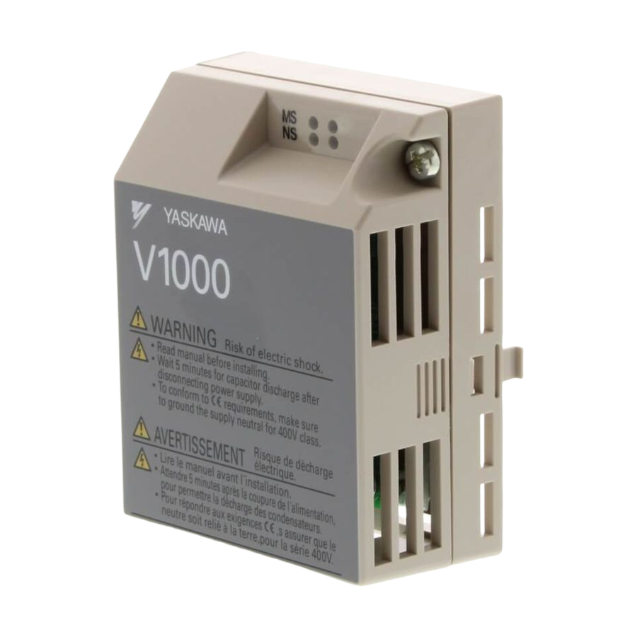
Page 12: Option Components
<2> A selection of ground wires are packaged loose in the option shipping package. Connect the appropriate ground wire based on drive model during installation. Figure 1 Option Unit Components YASKAWA ELECTRIC TOBP C730600 60C V1000 Option SI-EN3/V Installation Manual... - Page 13 4 Option Components Dimensions The installed option adds 27 mm (1.06 in.) to the total depth of the drive. Figure 2 V1000 27 mm (1.06 in.) Figure 2 Dimensions YASKAWA ELECTRIC TOBP C730600 60C V1000 Option SI-EN3/V Installation Manual...
- Page 14 The communication connector on the option is a modular RJ45 female connector designated CN1. CN1 is the connection point for a customer-supplied male Ethernet network communication cable. Figure 3 V1000 Figure 3 Communication connector CN1 (RJ45) YASKAWA ELECTRIC TOBP C730600 60C V1000 Option SI-EN3/V Installation Manual...
- Page 15 <1> 6 (Pair 3) Receive data (RXD) - 7 (Pair 4) Not used <1> 8 (Pair 4) Not used <1> <1> Not used for 10 Mbps and 100 Mbps networks. YASKAWA ELECTRIC TOBP C730600 60C V1000 Option SI-EN3/V Installation Manual...
- Page 16 10 Mbps is established 10/100 <1> Green 100 Mbps is established Green Link is not established – LINK/ Green Link is established Link is established and there is <1> Green Flashing network activity YASKAWA ELECTRIC TOBP C730600 60C V1000 Option SI-EN3/V Installation Manual...
- Page 17 The LEDs then assume operational conditions as shown in Table Table 5 Power-Up Diagnostic LED Sequence Sequence Module Status (MS) Network Status (NS) Time (ms) Green Green – Green Green Green Green – YASKAWA ELECTRIC TOBP C730600 60C V1000 Option SI-EN3/V Installation Manual...
-
Page 18: Installation Procedure
Do not allow unqualified personnel to perform work on the drive or option. Failure to comply could cause death or serious injury. Only authorized personnel familiar with installation, adjustment, and maintenance of AC drives and options may perform work. YASKAWA ELECTRIC TOBP C730600 60C V1000 Option SI-EN3/V Installation Manual... - Page 19 Failure to comply could prevent proper operation and damage equipment. Confirm that all connections are correct after installing the option and connecting peripheral devices. Failure to comply could damage the option. YASKAWA ELECTRIC TOBP C730600 60C V1000 Option SI-EN3/V Installation Manual...
- Page 20 The remaining installation steps differ based on drive model. Find the drive model number on the drive nameplate and refer to the step indicated in Table 6 based on your model number. YASKAWA ELECTRIC TOBP C730600 60C V1000 Option SI-EN3/V Installation Manual...
- Page 21 Figure 6 V1000 Terminal Cover Bottom Cover Figure 6 Remove the Terminal Cover and Bottom Cover on an IP20/Open-Chassis Drive (Models CIMR-VBA0006B to BA0018B; 2A0008B to 2A0069B; 4A0001B to 4A0038B) YASKAWA ELECTRIC TOBP C730600 60C V1000 Option SI-EN3/V Installation Manual...
- Page 22 2A0004 BA0003 2A0006 4A0001 4A0002 BA0006 2A0010 4A0004 BA0010 200/7.9 2A0012 4A0005 BA0012 2A0020 4A0007 BA0018 4A0009 4A0011 2A0030 4A0018 250/9.8 – 2A0040 4A0023 2A0056 4A0031 400/15.7 – 2A0069 4A0038 YASKAWA ELECTRIC TOBP C730600 60C V1000 Option SI-EN3/V Installation Manual...
- Page 23 Note: Installing the option on an IP20/NEMA Type 1 enclosure drive voids NEMA Type 1 protection while maintaining IP20 conformity. Figure 8 V1000 Figure 8 Remove the NEMA Type 1 Terminal Cover (CIMR-VBA0001F to BA0003F, 2A0001F to 2A0006F) YASKAWA ELECTRIC TOBP C730600 60C V1000 Option SI-EN3/V Installation Manual...
- Page 24 Note: The four different ground wires packaged with the option connect the option to different drive models. Select the proper ground wire depending on drive size. Refer to Table 7 on page ground wire selection by drive model. YASKAWA ELECTRIC TOBP C730600 60C V1000 Option SI-EN3/V Installation Manual...
- Page 25 NEMA Type 1 conduit Ground wire bracket screw Ground wire Figure 11 Reattach the NEMA Type 1 Conduit Bracket and Connect the Ground Wire for models CIMR-VBA0001F to BA0003F, 2A0001F to 2A0006F YASKAWA ELECTRIC TOBP C730600 60C V1000 Option SI-EN3/V Installation Manual...
- Page 26 Figure 14 for drive models CIMR-VBA0006 to BA0018, 2A0008 to 2A0020, and 4A0001 to 4A0011, which require routing the ground wire through the provided notch when reinstalling the terminal cover. YASKAWA ELECTRIC TOBP C730600 60C V1000 Option SI-EN3/V Installation Manual...
- Page 27 (Models CIMR-VBA0006 to BA0018; 2A0008 to 2A0069; 4A0001 to 4A0038) Figure 14 V1000 Ground wire routing notch Figure 14 Terminal Cover Ground Wire Notch (Models CIMR-VBA0006 to BA0018; 2A0008 to 2A0020; 4A0001 to 4A0011) YASKAWA ELECTRIC TOBP C730600 60C V1000 Option SI-EN3/V Installation Manual...
- Page 28 Remove the option cover and pass the ground wire through the inside of the drive bottom cover and into the through-hole for the ground wire at the front of the option. Figure 15 V1000 Option Cover Figure 15 Ground Wire Routing YASKAWA ELECTRIC TOBP C730600 60C V1000 Option SI-EN3/V Installation Manual...
- Page 29 Connect the ground wire at the option ground terminal. Tighten the screw to 0.5 to 0.6 Nm or (4.4 to 5.3 in lbs) using an M3 Phillips screwdriver. Figure 17 V1000 Option ground terminal Figure 17 Connect the Ground Wire to the Option YASKAWA ELECTRIC TOBP C730600 60C V1000 Option SI-EN3/V Installation Manual...
- Page 30 Using a cable not specifically recommended may cause the option or drive to malfunction. The use of Cat5e or equivalent Shielded Twisted Pair (STP) cable is recommended. Refer to the ODVA website for more information on network cabling (http:// www.odva.org). YASKAWA ELECTRIC TOBP C730600 60C V1000 Option SI-EN3/V Installation Manual...
- Page 31 Power Motor V1000 <1> SI-EN3/V EtherNet/IP Option EtherNet/IP Cable EtherNet/IP Master <1> The ground wire provided in the option shipping package must be connected during installation. Figure 19 Wiring Diagram YASKAWA ELECTRIC TOBP C730600 60C V1000 Option SI-EN3/V Installation Manual...
- Page 32 Other areas: Check the back cover of these manuals. Note: Download the EDS file for SI-EN3/V option. The SI-EN3/V will not function as a slave in the network without the appropriate EDS file. YASKAWA ELECTRIC TOBP C730600 60C V1000 Option SI-EN3/V Installation Manual...
-
Page 33: Related Drive Parameters
Range: 0, 1 1: Reset - Back to factory default Note: The setting value is not changed even when F6-08 is set to 1 and the drive is initialized using A1-03. YASKAWA ELECTRIC TOBP C730600 60C V1000 Option SI-EN3/V Installation Manual... - Page 34 Parameter F7-09 sets the most significant octet. Max: 255 <5> F7-10 Default: 168 Sets the static/fixed Gateway address. (3EE) Gateway Address 2 Min: 0 Parameter F7-10 sets the second most significant octet. Max: 255 <5> YASKAWA ELECTRIC TOBP C730600 60C V1000 Option SI-EN3/V Installation Manual...
- Page 35 IP Class ID 2AH Object. Max.: 15 Default: 0 F7-22 EtherNet/IP Time Sets the scaling factor for the time monitor in EtherNet/IP Min.: -15 (3FA) Scaling Class ID 2AH Object. Max.: 15 YASKAWA ELECTRIC TOBP C730600 60C V1000 Option SI-EN3/V Installation Manual...
- Page 36 <7> Set F7-15 when F7-14 is set to 0 or 2. <8> The setting values differ by drive software version. 1012 to 1015 Default: 0 Range: 0, 10, 100 ≥ 1016 Default: 10 Range: 10, 100 YASKAWA ELECTRIC TOBP C730600 60C V1000 Option SI-EN3/V Installation Manual...
- Page 37 – U6-98 and U6-99 on page 52 for details. Displays current option fault. Refer to Option Fault U6-99 Current Fault – Monitors U6-98 and U6-99 on page 52 for details. YASKAWA ELECTRIC TOBP C730600 60C V1000 Option SI-EN3/V Installation Manual...
-
Page 38: Configuring Messaging
Torque Status Input (Vendor Specific Yaskawa Electric (YE) Assy)- Extended 155 (9B) Input – Speed/ Torque Status Input (Vendor Specific Yaskawa Electric (YE) Assy)-High 166 (A6) Input – Speed/Torque Status Input YASKAWA ELECTRIC TOBP C730600 60C V1000 Option SI-EN3/V Installation Manual... -
Page 39: Output Assemblies (Drive Consumes)
Setting range: 0 to 0xFFFF Example: setting a reference of 4096 with a speed scale of 2: Speed reference data = 4096/2 = 1024 = 0x0400 Hex or 10.24 Hz Unit depends on o1-03. YASKAWA ELECTRIC TOBP C730600 60C V1000 Option SI-EN3/V Installation Manual... - Page 40 Setting range: 0 to 0xFFFF For example, when setting a reference of 4096 with a speed scale of 2: Speed reference data = 4096/2 = 1024 = 0x0400 Unit depends on o1-03. YASKAWA ELECTRIC TOBP C730600 60C V1000 Option SI-EN3/V Installation Manual...
-
Page 41: Input Assemblies (Drive Produces)
Range: 0 to 0xFFFF For example, when output frequency of 1024 with a speed scale of 2: Speed actual data = 1024 x 2 = 4096 = 0x1000 Unit depends on o1-03. YASKAWA ELECTRIC TOBP C730600 60C V1000 Option SI-EN3/V Installation Manual... - Page 42 Range: 0 to 0xFFFF For example, when output frequency of 1024 with a speed scale of 2: Speed actual data = 1024 x 2 = 4096 = 0x1000 Unit depends on o1-03. YASKAWA ELECTRIC TOBP C730600 60C V1000 Option SI-EN3/V Installation Manual...
-
Page 43: Web Interface
MAC address, and firmware version. This page also shows the status of the option and provides links to the other embedded web pages. Figure 20 Figure 21 Main Page View YASKAWA ELECTRIC TOBP C730600 60C V1000 Option SI-EN3/V Installation Manual... - Page 44 10 Web Interface Drive Status Page (Status, Monitor and Fault History) The embedded drive status page shows basic I/O information and drive state information. Figure 21 Figure 22 Drive Status Page View YASKAWA ELECTRIC TOBP C730600 60C V1000 Option SI-EN3/V Installation Manual...
- Page 45 Network Monitor Page (Network Monitor) The embedded network monitor page shows the status of the option network traffic and open I/O connections. Figure 22 Figure 23 Network Monitor Page View YASKAWA ELECTRIC TOBP C730600 60C V1000 Option SI-EN3/V Installation Manual...
- Page 46 Clicking this resets the Consume Msg Cnt and the Produce Msg Cnt for this connection Connection1 to start counting from zero. Note: Network monitors are reset when the power supply is cycled. YASKAWA ELECTRIC TOBP C730600 60C V1000 Option SI-EN3/V Installation Manual...
-
Page 47: Troubleshooting
• Separate all communication wiring from drive power lines. Install an EMC noise filter to the drive power supply input. • Counteract noise in the master controller (PLC). YASKAWA ELECTRIC TOBP C730600 60C V1000 Option SI-EN3/V Installation Manual... - Page 48 Cause Possible Solution The option connected to De-energize the drive and plug the option into the drive according to Installation option port CN5-A was Procedure on page changed during run. YASKAWA ELECTRIC TOBP C730600 60C V1000 Option SI-EN3/V Installation Manual...
- Page 49 Turn off the power. The option card connection Check if the option is properly plugged into the option port. to port CN5-A is faulty. Replace the option if the fault continues to occur. YASKAWA ELECTRIC TOBP C730600 60C V1000 Option SI-EN3/V Installation Manual...
- Page 50 Termination resistor of the MEMOBUS/Modbus Set DIP switch S2 to the ON position to enable the termination communications is not resistor on a drive located at the end of a network line. enabled. YASKAWA ELECTRIC TOBP C730600 60C V1000 Option SI-EN3/V Installation Manual...
- Page 51 Note: Refer to the MEMOBUS/Modbus Data Table in the MEMOBUS/Modbus Communications chapter of the drive manual for a list of monitor data using the MEMOBUS/Modbus message area. YASKAWA ELECTRIC TOBP C730600 60C V1000 Option SI-EN3/V Installation Manual...
- Page 52 If another fault occurs while the original fault is still active, parameter U6-98 retains the original fault value and U6-99 stores the new fault status value. YASKAWA ELECTRIC TOBP C730600 60C V1000 Option SI-EN3/V Installation Manual...
-
Page 53: European Standards
Keep wiring as short as possible and ground the largest possible surface area of the shield to the metal panel according to Figure YASKAWA ELECTRIC TOBP C730600 60C V1000 Option SI-EN3/V Installation Manual... - Page 54 EMC Filter and Option Installation for CE Compliance Figure 25 V1000 Enclosure panel Cable clamp Drive Communication option EMC filter Upper controller Three phase power supply Figure 26 EMC Filter and Option Installation for CE Compliance YASKAWA ELECTRIC TOBP C730600 60C V1000 Option SI-EN3/V Installation Manual...
-
Page 55: Specifications
• Radioactive materials or flammable materials, including wood Area of Use • Harmful gas or fluids • Salt • Direct sunlight • Falling foreign objects Altitude 1000 m (3280 ft.) or lower YASKAWA ELECTRIC TOBP C730600 60C V1000 Option SI-EN3/V Installation Manual... - Page 56 Revision: Reviewed and corrected entire documentation. Chapter 7 Addition: Information on assemblies 115 and 155. Chapter 12 Addition: European Standards Back cover Revision: Address − − March 2012 First edition YASKAWA ELECTRIC TOBP C730600 60C V1000 Option SI-EN3/V Installation Manual...
- Page 57 Phone: +81-3-5402-4502 Fax: +81-3-5402-4580 http://www.yaskawa.co.jp YASKAWA AMERICA, INC. 2121, Norman Drive South, Waukegan, IL 60085, U.S.A. Phone: +1-800-YASKAWA (927-5292) or +1-847-887-7000 Fax: +1-847-887-7310 http://www.yaskawa.com YASKAWA ELÉTRICO DO BRASIL LTDA. 777, Avenida Piraporinha, Diadema, São Paulo, 09950-000, Brasil Phone: +55-11-3585-1100 Fax: +55-11-3585-1187 http://www.yaskawa.com.br...
Need help?
Do you have a question about the V1000 and is the answer not in the manual?
Questions and answers