Advertisement
A S S E M B LY I N S T R U C T I O N S
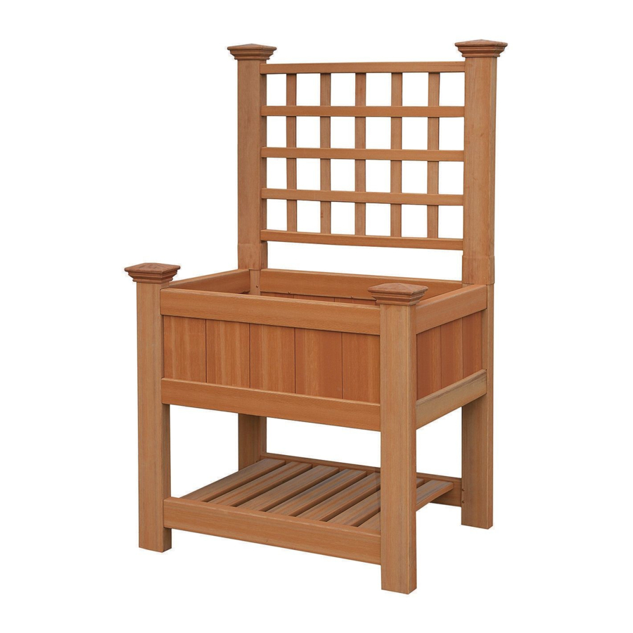
The Raised Planter Trellis*
*The Raised Planter Trellis is designed to mount on to our 24" x 36" White Raised Planter Box (sold separately) as shown above.
Please read through before starting assembly.
IMPORTANT: CHECK THE INSIDE OF YOUR POSTS FOR ALL MATERIALS.
Check Box for These Contents
In the event of missing or defective parts please call our customer service department at 1 800 282 9346, ext #20
(Mon. to Fri. 8:00 AM to 4:00 PM EST).
1. Posts (2)
2. Top and Bottom Rails (2) - 1.5" x 1.5" x 35.75"
3. Horizontal Spindles (3) - 1.5" x .875" x 31"
4. Vertical Spindles (5) - 1.5" x .25" x 21"
5. 1" Self-Auguring Stainless Steel Screw (4)
Tools You Will Need
• Cordless Drill
General Information
• Read Instructions through carefully before beginning assembly.
• When assembling components, place on a non-abrasive surface
(i.e. shipping box) to avoid scratching.
• We recommend an area approx 5'x 8' for unobstructed assembling.
• You should not need to use excessive force when assembling component.
¡
¢
£
1
2
3
4
5
Not to Scale
www.newenglandarbors.com
¦
¢
£
¢
£
¤
¥
¦
§
¦
¢
£
1
Ver 1/OCT 2012
Advertisement
Table of Contents

Related Manuals for New England Arbors The Raised Planter Trellis


Summary of Contents for New England Arbors The Raised Planter Trellis
- Page 1 ¢ £ *The Raised Planter Trellis is designed to mount on to our 24” x 36” White Raised Planter Box (sold separately) as shown above. Please read through before starting assembly. IMPORTANT: CHECK THE INSIDE OF YOUR POSTS FOR ALL MATERIALS.
- Page 2 S T E P O N E Align and insert the five vertical spindles into the horizontal spindle as shown. Note the spacing between the horizontal rails are to match that of the posts. Align and insert the top and bottom rails as shown. Insert the lattice from step 2 into the routed holes on the posts as shown.
Need help?
Do you have a question about the The Raised Planter Trellis and is the answer not in the manual?
Questions and answers