Table of Contents
Advertisement
Advertisement
Table of Contents

Subscribe to Our Youtube Channel
Related Manuals for Datalogic STS320 Series


Summary of Contents for Datalogic STS320 Series
- Page 1 STS320™ INSTALLATION GUIDE Solution for Tires Sorting...
- Page 2 Electronic versions of this document may be downloaded from the Datalogic website (www.datalogic.com). If you visit our website and would like to make comments or suggestions about this or other Datalogic pub- lications, please let us know via the "Contact" page.
-
Page 3: Table Of Contents
CONTENTS PREFACE ........................V About this Manual ......................v Manual Conventions ..........................v Technical Support ......................v Support Through the Website ......................v Reseller Technical Support ......................... v COMPLIANCE ......................VI General .......................... vi Power Supply ......................... vi EMC Compliance ......................vi CE Compliance ........................ - Page 4 CONTENTS Quick Start ............................23 Ethernet Device Discovery ........................ 23 Device Configuration .........................24 Backup and Restore Through DL.CODE ...................25 Backup ............................25 Restore ............................26 Replacement ..........................26 TROUBLESHOOTING ....................27 General Guidelines ......................27 STS320...
-
Page 5: Preface
WARNING TECHNICAL SUPPORT Support Through the Website Datalogic provides several services as well as technical support through its website. Log on to (www.datalogic.com). For quick access, from the home page click on the search icon , and type in the name of the product you’re looking for. -
Page 6: Compliance
Datalogic commercial reference contacts. Since April 20th, 2016 the main European directives applicable to Datalogic products require inclusion of an adequate analysis and assess- ment of the risk(s). This evaluation was carried out in relation to the applicable points of the standards listed in the Declaration of Conformity. -
Page 7: Laser Safety
Put them on the product instead of the English version. To be applied on each Matrix 320 ATS-xxx To be applied on the mounting bracket LED SAFETY For all Datalogic STS320 compatible internal illuminators, LED emission is classified into Risk Group 1 according to EN 62471:2010. INSTALLATION GUIDE VII... -
Page 8: Handling
HANDLING The STS320 is designed to be used in an industrial environment and is built to withstand vibration and shock when correctly installed, however it is also a precision product and therefore before and during installation it must be handled correctly to avoid damage. •... -
Page 9: General View
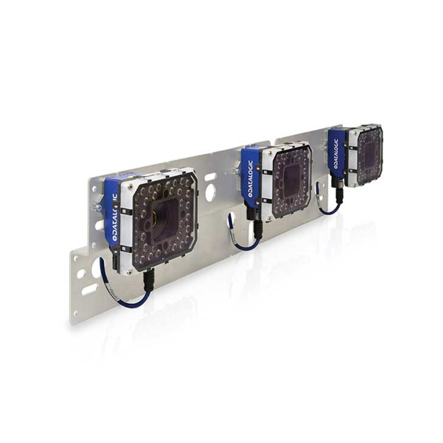
GENERAL VIEW Figure 1- STS320 (14 LEDs illuminator) Figure 2 - STS320 (36 LEDs illuminator) 1. ID-NET™ Master 4. Positioning Slot 2. ID-NET™ Slaves 5. Reading Windows 3. Mounting Slots 6. Laser Class and Warning Labels INSTALLATION GUIDE IX... - Page 10 X STS320...
-
Page 11: Introduction
CHAPTER 1 INTRODUCTION STS320, which means Solution for Tires Sorting, is a solution designed to be easily inte- grated into a sorting system for reading barcodes on tires. MODEL DESCRIPTION The models differ by application type, code resolution, and number of readers. PACKAGE CONTENTS Verify that the STS320 and all the parts supplied with the equipment are present and intact when opening the packaging. -
Page 12: Power Requirements
INTRODUCTION POWER REQUIREMENTS The STS320 solution kit doesn’t include a power supply unit, which has to be ordered separately. The maximum power required depends on the model. Power is supplied to the system through its connection box CBX500. The following table indicates the compatible power supply to use according to the STS320 model. -
Page 13: Installation
CHAPTER 2 INSTALLATION MOUNTING DISTANCE Vertical Min. Max. Code Reading Focus Model Readers DOF* Reading Reading Resolution Width Distance @ min. Distance Distance distance (mils) (in) (in) (in) (in) (in) (in) STS320-003 (37.4) 0.30 1080 (12) (32.68) (42.52) (37.01) (7.95) 1250 STS320-004 (49.21) - Page 14 INSTALLATION Figure 3 - STS320 (14 LEDs illuminators) mounting distance Figure 4 - STS320 (36 LEDs illuminators) mounting distance 4 STS320...
-
Page 15: Sts320 Main Plate Mounting
STS320 MAIN PLATE MOUNTING STS320 MAIN PLATE MOUNTING Once the supporting profile has been positioned at the correct height we can proceed with the STS320 mechanical mounting. STS320 has been designed to be easily installed by one person using the T-bolt, special plate supporting nut and locknut supplied in the kit: Figure 5 - STS320 Plate Supporting Nut The plate supporting nut has to be coupled to the frame with the M8 x 25 mm T-bolt:... - Page 16 INSTALLATION The STS320 has to be installed onto the station frame in the conveyor direction so that the main plate slot (reader side) is aligned with the plate support assembly. Slide the main plate slot between the plate support assembly and the supporting profile until it reaches the end.
-
Page 17: Presence Sensor Positioning
PRESENCE SENSOR POSITIONING PRESENCE SENSOR POSITIONING The STS320 system comes with a pair of photocells that can be used to detect the pres- ence of the tire on the conveyor and trigger the beginning and the end of the reading phase. - Page 18 NOTE maximize the reading area. Smaller gaps can be used and maximized by modifying the configuration. Please contact your local Datalogic representative for feasibility. 8 STS320...
-
Page 19: Electrical Connections
CHAPTER 3 ELECTRICAL CONNECTIONS STS320 WIRING DIAGRAM Figure 9 - STS320 Array Wiring INSTALLATION GUIDE 9... -
Page 20: Power Supply
ELECTRICAL CONNECTIONS POWER SUPPLY Power is supplied through the CBX500 spring clamp terminal pins as shown in the figure below. Figure 10 - Power Supply Connections For all STS320 models the power must be 24 Vdc only. It is recommended to connect the array CHASSIS to earth ground (Earth) by setting the appropriate jumper in the CBX connection box. -
Page 21: Digital Inputs
DIGITAL INPUTS DIGITAL INPUTS There are two optocoupled polarity insensitive inputs available on the reader: Input 1 (External Trigger) and Input 2, a generic input: These inputs can be used to control (start/stop) the reading phase: Parameter Reading Phase ON Input Reading Phase OFF Input Source Single Presence... -
Page 22: Input Connections For Presence Sensors (Provided In The Package)
ELECTRICAL CONNECTIONS Input Connections for Presence Sensors (provided in the package) Power is available directly to the Input Device, independently of the Power Supply Switch inside the CBX. NOTE The sensors included in the STS320™ have a standard pinout (brown = +Vdc; blue = GND;... -
Page 23: Input Connections From Plc
DIGITAL INPUTS Sensor 2 CBX500 Row 2 Function Power Source - External Trigger brown Input 2 A (polarity insensitive) black Input 2 B (polarity insensitive) blue -V (bridge to I2B) Power Reference - Inputs Figure 13 - Presence Sensor Connected to Input 2 Input Connections from PLC Alternatively, the reading system can be controlled by a digital output of a PLC. -
Page 24: Digital Outputs
ELECTRICAL CONNECTIONS Figure 14 - External Trigger Connected to PLC The yellow Trigger LED on the reader is on when the active state of the External Trigger corresponds to ON. PLC Signal CBX500 Row 3 Function Input Input 2 A (polarity insensitive) Reference Input 2 B (polarity insensitive) Figure 15 - Input 2 Connected to PLC... -
Page 25: Output Connections Using Sts320 Power
DIGITAL OUTPUTS Output Connections Using STS320 Power Power is available directly to the Output Device, independently of the Power Supply Switch inside the CBX. CAUTION The digital outputs can power and drive small devices meeting the electrical character- istics above such as electronic switches which can then manage larger power consuming devices such as signaling lights or other machinery. -
Page 26: Software Configuration
CHAPTER 4 SOFTWARE CONFIGURATION There are two main methods that can be used to complete the STS320 installation. The first regards stations that do not need any application specific parameter configura- tion. The factory default configuration is sufficient and the only necessary steps are to align the Master IP Address to the Host LAN through a web browser using the Web Dis- covery feature, then backup the configuration through the CBX500 menu. - Page 27 CONFIGURATION USING WEB DISCOVERY This page shows all devices available in the network: Click on the wrench icon and input the correct IP Address settings (from network admin- istrator) and optional Device Description for each reader. At least one device must be reachable from the user PC. For example, if there are several subnetworks, at least one device must be in the same subnetwork of the PC.
-
Page 28: Backup Procedure Using Cbx500 Hmi Interface
SOFTWARE CONFIGURATION BACKUP PROCEDURE USING CBX500 HMI INTERFACE Keypad and Display The CBX500 display can be used with the three buttons below it. The up arrow button allows you to scroll up through the menu. The down arrow button allows you to scroll down through the menu. -
Page 29: Web Monitor
WEB MONITOR WEB MONITOR Web Monitor is a remote monitoring tool provided to visualize STS320 in its run-time environment. You can access it from the DL.CODE Task area, from the Discovery page, or from your browser by inputting the IP address of the reader. STS320 must be available on the LAN. -
Page 30: Statistics Page
SOFTWARE CONFIGURATION The Stop/Play button allows you to stop image monitoring to save a particular image. The reader continues to run, only the monitored image is stopped. The Save image button automatically downloads the current image as a jpg file to the browser’s default Download folder. The default naming syntax is image_weekday month day year.jpg (i.e. -
Page 31: Diagnostics Page
WEB MONITOR Diagnostics Page Web Mosaic The Web pages of the Master reader include the Mosaic view, which is helpful to check the system behavior at a glance. As shown in the figure above, a scaled version of the images acquired in each reading phase is retrieved from all readers and arranged side by side in a single frame. -
Page 32: Configuration Using Dl.code
SOFTWARE CONFIGURATION The 20 most recent reading phases are stored in temporary memory and can be retrieved by switching to Pause Mode and using the arrow buttons (Pause Mode stops image collection). In Pause Mode, images can be zoomed in with the Zoom button and the mouse wheel, and saved in a single .png file using the Save button: In both operating modes, details of the currently displayed phase are shown in the sta- tus bar:... -
Page 33: Quick Start
CONFIGURATION USING DL.CODE Quick Start Figure 18 - Main window areas To help you get started, here is an example configuration demonstrating the basic steps of DL.CODE configuration. To configure your device for your application, the following preliminary steps are assumed: •... -
Page 34: Device Configuration
SOFTWARE CONFIGURATION 5. Double-click on or drag the device icon into the Selected Device Information Area. Details about the device will be displayed in this area. For Image Saving applications or to take full advantage of the Mosaic feature, you will need to connect the Slave readers to the network, one at a time, and assign IP Addresses to them. -
Page 35: Backup And Restore Through Dl.code
CONFIGURATION USING DL.CODE Backup and Restore Through DL.CODE DL.CODE allows Backup and Restore to be performed to/from the configuration PC via file and to the BM100 external storage device inside the CBX500 (both are recom- mended). DL.CODE provides complete backup and restore functions (Configuration and Environ- mental parameters): For Master Readers in ID-NET Master/Slave networks: •... -
Page 36: Restore
SOFTWARE CONFIGURATION Restore To perform a Restore, from the DL.CODE Device menu, select Restore from external storage device and follow the procedure; then perform a backup selecting Internal Net- work replacement (from a file on PC) and follow the procedure. Replacement The replacement device must be the exact same model as the device it is replacing. -
Page 37: Troubleshooting
• If you are unable to fix the problem and you are going to contact your local Datalogic office or Datalogic Partner or ARC, we suggest providing (if possible): Application Program version, Parameter configuration file, Serial Number and Order Number of your reader. - Page 38 Troubleshooting Guide for STS320 Solutions Problem Suggestion •If a trigger signal is active and no code is present Does the internal lighting under the system, all readers must flash blue or system work correctly? red. If this is not the case, please replace the reader and send it to repair.
- Page 40 © 2020 Datalogic S.p.A. and /or its affiliates • All rights reserved • Without limiting the rights under copyright, no part of this documentation may be reproduced, stored in or introduced into a retrieval system, or transmitted in any form or by any means, or for any purpose, without the express written permission of Datalogic S.p.A.
Need help?
Do you have a question about the STS320 Series and is the answer not in the manual?
Questions and answers