
Related Manuals for Datalogic Falcon 4410


Summary of Contents for Datalogic Falcon 4410
-
Page 1: Product Reference Guide
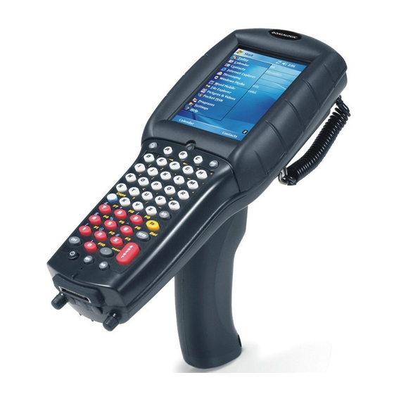
Falcon 4410 26-Key model Falcon 4400 Series ® with Windows Falcon 4420 48-Key model Product Reference Guide ® Falcon 4410 52-Key NU model... - Page 2 Datalogic Mobile, Inc 1505 Westec Dr. Eugene, Oregon 97402 Telephone: (541) 743-4800 Fax: (541) 743-4900 An Unpublished Work - All rights reserved. No part of the contents of this documentation or the procedures described therein may be reproduced or transmitted in any form or by any means without prior written permission of Datalogic Mobile, Inc.
-
Page 3: Table Of Contents
Preface: About this Guide ... vii Chapter 1. Batteries and Power ... 1-1 Overview ...1-1 Suspend Mode ...1-1 Suspending ...1-1 Resuming ...1-2 Battery Warnings and Cautions ...1-2 Battery Disposal ...1-4 Chapter 2. Configuring the Falcon... 2-1 Overview ...2-1 Backlight ...2-2 Bluetooth Manager ...2-4 Search for device ...2-4 Connect to a Bluetooth Device ...2-4... - Page 4 Contents Network and Dialup ... 2-27 Owner ... 2-28 Password ... 2-28 PC Connection ... 2-29 Persistent Registry ... 2-29 Power Configuration ... 2-30 Regional Settings ... 2-31 Remove Programs ... 2-32 Storage Properties ... 2-32 Stylus Calibration ... 2-33 System Properties ...
- Page 5 Softcases ...A-7 Installing the Handle or Handstrap ...A-8 Installing the Handstrap on the Falcon 4420 ...A-8 Installing a Handle on the Falcon 4410 ...A-9 Tethered Stylus ... A-10 Installing a Tethered Stylus ... A-10 Removing a Tethered Stylus ... A-11 Appendix B.
- Page 6 Contents Appendix C. Configuring the Web Server... C-1 Overview ... C-1 Enabling the Web Server ... C-1 Setting Up a User ... C-2 Testing the Web Server ... C-3 Launching the Network Administration Page ... C-4 Web Server Registry Settings ... C-4 Creating and Using an ISAPI Service ...
- Page 7 RSS-14 ...G-21 RSS Limited ...G-22 RSS Expanded ...G-22 Standard 2 of 5 ...G-24 Trioptic ...G-26 UPC-A ...G-26 UPC-E ...G-28 UPC/EAN Extensions ...G-29 2D Symbologies ...G-30 Aztec Code ...G-30 DataMatrix ...G-32 Composite ...G-34 Maxicode ...G-36 OCR ...G-38 PDF-417 ...G-39 MicroPDF-417 ...G-41 QR Code ...G-43 Imager Labels ...G-45 Other Controls ...G-45...
- Page 8 Contents NOTES ® ® Falcon 4400 Series with Windows...
-
Page 9: Preface: About This Guide
Chapter 2, Configuring the Falcon, uses the control panels to adjust touchscreen calibration, date and time, display backlight/ contrast, volume/sounds, scanner, power, and memory. Chapter 3, Software Applications, covers flash memory, install- ing, selecting, using, and removing applications, entering data, and using the soft input panel with Inbox, Internet Explorer, and Word Pad. - Page 10 Preface • • • • • • • • Registering Your Datalogic Mobile Product Datalogic Mobile values your feedback. Please take a few moments and complete the Product Registration form located on our website. Registering your products ensures that you will be informed of the latest product news, technical specifications, software updates and other future developments from Datalogic Mobile.
-
Page 11: Document Conventions
Document Conventions Formatting conventions are used throughout this guide to provide a consistent method for representing screen shots, command entries, and keyboard characters. This guide also provides special conventions for notes and cautions, information of high interest. NOTES contain information necessary for properly diagnosing, repairing and operating the terminal. -
Page 12: Stylus Actions
Preface Stylus Actions Stylus actions apply to the Falcon only; most PCs use a mouse as an input device. Tap or Select. specific button or select an item from a pull-down list. Double-Tap. an application. Tap and Hold. Refer to the Quick Reference Guide (QRG) for more information on using a stylus with the Falcon. -
Page 13: Chapter 1. Batteries And Power
Overview This section contains the following topics: • "Suspend Mode" starting on page • "Battery Warnings and Cautions" on page • "Battery Disposal" starting on page 1-4. Suspend Mode The Falcon will go into a suspend or sleep mode when it is idle for a period of time. -
Page 14: Resuming
Batteries and Power Resuming Use one of the following methods to resume (wake up the Falcon): • Press • Put the Falcon into a dock. • Press the When a battery pack is fully discharged while the unit is in suspend mode, the Falcon remains in the suspended mode until the battery pack is charged or external power is supplied via the dock or a power cable. - Page 15 Battery Warnings and Cautions Always charge the battery at 32°–113°F (0°–45°C) temperature range. If you remove the battery pack or it becomes completely discharged, there is a 30 minute window in which to insert a charged battery pack before the backup bat- CAUTION tery fails.
-
Page 16: Battery Disposal
Batteries and Power Battery Disposal If you must dispose of a battery pack, please follow the CAUTIONS below: Use only a battery pack supplied by a Datalogic Mobile reseller for this device.The use of other battery supplies can damage the Falcon and void your warranty. Con- tact your reseller to for the correct power supplies;... -
Page 17: Chapter 2. Configuring The Falcon
Configuring the Falcon Overview This section contains the following topics on configuring your Falcon. Most control panels are accessed by selecting/tapping Start > Settings > Control Panel • "Backlight" on page • "Bluetooth Manager" on page • "Certificates" on page •... -
Page 18: Backlight
Configuring the Falcon • "Regional Settings" on page • "Remove Programs" on page • "Storage Properties" on page • "Stylus Calibration" on page • "System Properties" on page • "Volume and Sounds" on page • "Wi-FI" on page Backlight Increasing backlight brightness can cause the battery pack to discharge at a faster rate. - Page 19 Figure 2-1. Backlight Control Panel & Brightness 4. On the desired options from the pull-down lists (refer to 5. On the them (refer to • • • Using Auto-on while running from battery power will cause the battery pack to discharge at a faster rate.
-
Page 20: Bluetooth Manager
Configuring the Falcon Bluetooth Manager Search for device 1. Select Bluetooth 2. Search for the type of Device(s) you want to connect to by tapping Printer, Serial, or All within range. 3. If you attempt to set up a connection when the Bluetooth Radio is disabled, you will receive a message reminding you that the radio is turned off, and asking you if you want to turn it on. - Page 21 2. The resulting dialog will display services that are available on the device. Select the service you want to connect to. The following table shows the icons that display for different types of service. Table 2-1. Bluetooth Device Icons Icon Virtual Port nicate serially with an incoming device just as if it were a physical COM port.
-
Page 22: Viewing Or Deleting Paired Devices
Configuring the Falcon You can also select apply or modify those settings. 1. To require Authentication, tap the checkbox, then tap 2. The Authentication Request dia- log will then open, requesting that you enter a PIN. Use the Input Panel to type in the PIN. 3. -
Page 23: Settings
The icons displayed in the taskbar at the bottom of your Falcon’s screen will show you the state of the Bluetooth connection, as shown in Table 2-2. Bluetooth taskbar icons Icon Settings Settings ify settings for Incoming Connections. Tapping Find Me 60 seconds, allowing them to set up a connection. -
Page 24: Certificates
Configuring the Falcon Certificates Certificates are used by some applications for establishing trust and to secure communications. See the Microsoft Windows CE help on your Falcon unit for further information about Certificates. Date and Time In this control panel, you can change the year, month, date, time, time zone, or select automatic adjust for Daylight Savings Time. -
Page 25: Decoding
Decoding You can configure the Falcon’s decoding options by tapping on > Control Panel > Decoding large numbers of terminals using There are two sections in the tional pages. There are six General Configuration pages and multiple Bar Code symbology pages. Other decoding parameters are described in Programming Parameters, starting on page F-1;... - Page 26 Configuring the Falcon Figure 2-5. Decoding Properties: General Options To view other configuration options, select • General Options IDs, Label Prefix, Label Suffix, and Data Separator options. Figure 2-6. Decoding Properties: Decoding Options To view other configuration options, select • Decoding Options: Redundancy 2-10...
- Page 27 Figure 2-7. Decoding Properties: Trigger Options To view other configuration options, select • Trigger Options: code, Image, and RFID (available in future versions). Select the desired radio buttons to define the button functions. Available items will vary depending on the model. Figure 2-8.
- Page 28 (the aiming beam and the illumination beam turn Concurrent (the aimer beam and illumination alternate Interlaced Brightness Timeout : Enable the keyboard wedge for bar code scanner, Magnetic Configure > 1D Bar Code ® Falcon properties using the sliders. Configure > General...
- Page 29 Figure 2-10. Available 1D Bar Code Symbologies Refer to the sample symbology control panels in the types of fields and options you can modify. Decoding parameters are described in Programming Parameters, starting on page F-1; bar code settings are provided in Programming Bar Codes, starting on page G-1.
-
Page 30: Bar Code Symbologies
Configuring the Falcon • Code 39 checksum, and Full ASCII conversion. • UPC-A 2D Bar Code Symbologies If you have the 2D Imager module installed, the following additional symbol- ogy options are also available: Refer to Figure 2-11 modify. Other decoding parameters are described in Programming Parameters, starting on page F-1;... -
Page 31: Settings
Settings Select from the previous configurations and/or other available default settings. Choose from: • Factory Defaults • Minimum Settings • Maximum Settings • Save (New Settings) • Reverts to Saved Settings The settings are saved when you select/ Display Configuration To change the default Background or Appearance (Windows Color Scheme), select Start >... -
Page 32: Appearance
Configuring the Falcon Appearance To change the default Windows color scheme: 1. Tap the 2. Tap the and select a new Windows color scheme if desired. 3. Tap press Falcon Config Start > Settings > Control Panel > Falcon Config ties such as the Falcon Management Utility (FMU) and Falcon Desktop Util- ity (FDU) settings. -
Page 33: Image Capture
Image Capture Capture To capture an image: 1. Aim the Falcon toward the image you want to capture. The screen will display a preview of the image, making use of the current settings (to change the settings, see "Image Settings" on page 2-20). 2. -
Page 34: Image File
Configuring the Falcon 4. A image file name will appear, unless that option has been pre- viously deselected in the tings (in that case, the file will automatically save without prompting). See "Image File" on page 2-18, to change settings. 5. -
Page 35: Image Size
Enable Long Range Filter tances (greater than 10 feet or 3 meters). Enable Aimer Illumination light for an image capture. Image Size On the Size erty settings as desired. Both keyboard and stylus input are supported. 1. Use the to adjust the image. •... -
Page 36: Image Settings
Configuring the Falcon Image Settings JPEG Quality ity when the JPEG image format is selected. Selecting a higher quality results in a higher quality image, but a larger file. Brightness brightness level the imager will use when taking images. Edge Sharpness much the imager will attempt to sharpen edges in images it takes. -
Page 37: Input Panel Properties
Table 2-3. Sample Imager Settings Condition Distance >10 ft (3 m) Low light Printed Text Signature Input Panel Properties To change the 1. Select Panel > Input Panel 2. Change the desired settings. 3. To change the Options 4. Change the soft keyboard options as desired, selecting from: •... -
Page 38: Internet Options
Configuring the Falcon 5. To exit the Options bar, or press pad. 6. To exit <Enter> Internet Options To change the 1. Select 2. On the desired start page and the desired search engine. You can also select a User Agent, change the tory. - Page 39 4. On the security settings for Internet, Local intranet, Trusted Sites, and Restricted Sites. Figure 2-14. Internet Settings 5. The tings by tapping the radio buttons. You can Accept, Block or receive a Prompt for First-party and Third-party Cookies. You can also Enable/ disable session cookies by selecting the check box.
- Page 40 Configuring the Falcon 6. On the tings for Accessibility, Browsing, Multimedia, and Security by tapping the check boxes. Figure 2-16. Advanced Internet and Popup Settings 7. The fication when popups have been blocked, and to open new pages in the current window. 8.
-
Page 41: Keyboard Configuration
Keyboard Configuration The keyboard control panel will appear different, depending upon which key- pad your Falcon has. 26-Key Keypad 1. Select > Keyboard Options Keyboard control panel. 2. Adjust the slider for ences. 3. Use the box provided to test the time-out delay. - Page 42 Configuring the Falcon Figure 2-17. 48-Key or 52-Key Keypad Control Panels 3. You can also adjust the slider for the keys repeat. 4. Use the box provided to test the selected repeat rate setting. 5. On the or change to the 6.
-
Page 43: Network And Dialup
Network and Dialup To change the Network and Dialup connection settings, complete these steps: 1. Select Figure 2-18. Changing Network & Dialup Settings. 2. Double-tap the connection to view or change the settings. The SDCCF10G1 on the radio installed and the number of connections. 3. -
Page 44: Owner
Configuring the Falcon Owner To change the 1. Select Panel > Owner Properties Input Panel entering data. 2. Enter data using the input panel or the keypad on the PDA. 3. To exit the control panel, tap control bar, or press the keypad. -
Page 45: Pc Connection
PC Connection PC Connection PDA. To modify the default settings: 1. Select Panel > PC Connection 2. Select the first checkbox to enable direct connections to the desktop computer. 3. Tap modify the connection method from USB or Serial. 4. To exit the dialog, tap bar, or press keypad. -
Page 46: Power Configuration
Configuring the Falcon Automatically persisting the registry at frequent intervals may slow system per- formance. Power Configuration To adjust power management settings, select . Use this control panel t Power Power settings. Battery Tab Battery Backup battery on the command bar, or press Power Off Tab Power Off initiation to save battery power as shown in Figure 2-19 on page 2-30. -
Page 47: Regional Settings
Regional Settings To change the Regional Settings 1. Select your locale from the dropdown box. See Figure 2-20 on page 2-31. 2. Review the Customize to change the appearance of Date. Figure 2-20. Region and Custom Settings 3. The options on the Language tab are disabled because the Falcon will display only in English. -
Page 48: Remove Programs
Configuring the Falcon Figure 2-21. Language and Input Tabs 5. To exit on the keypad. Remove Programs See "Removing Programs" on page 3-7. Storage Properties To change the 2-32 , tap on the control bar, or press Regional Settings control panel default settings: Storage Properties ®... -
Page 49: Stylus Calibration
1. Select Panel > Storage Properties 2. From the list, select the desired storage device. 3. You can also format, dismount, and create partitions on storage devices using this control panel. 4. To save and exit the Properties on the control bar, or press <Enter>... - Page 50 Configuring the Falcon Figure 2-22. Stylus Properties Control Panel 4. Tap open the tion to the right 5. Carefully press and briefly hold stylus on the center of the target as the target moves around the screen or press <ESC> stylus calibration.
-
Page 51: System Properties
System Properties Refer to the view the System properties, select erties. General Tab To view the expansion card settings, select Start > Settings > Control Panel > System Properties > General Firmware Tab Select Start > Settings > Control Panel > System Properties > Firmware the device serial number, model number, firmware version, and keyboard type. -
Page 52: Memory Configuration
Configuring the Falcon Figure 2-23. Serial Number Locations — LASER LIGHT IS EMITTED FRO Datalogic Mobile 1505 Westec Dr. PRODUCT OF USA Eugene, OR 97402 Complies with 21CFR and Part 15 of FCC rules. Item # 345-4201-005 DATE OF MANUF RADIO: BREEZECOM EUR: CE0560 CAN: 24611032079A... -
Page 53: Device Name
Device Name Your device uses this information to identify itself to other computers. Copyrights Refer to this tab for specific copyright data. As a user, you are responsible to read this statement. Product Reference Guide System Properties 2-37... -
Page 54: Volume And Sounds
Configuring the Falcon Volume and Sounds To change the 1. Select open the Figure 2-24. Volume and Sounds Control Panels 2. Set the volume by adjusting the slider from 3. Enable the desired sounds for key clicks, screen taps, notifications, and applications. -
Page 55: Wi-Fi
Wi-FI About the Summit Client Utility The Summit Client Utility (SCU) is an application designed for end users and administrators of mobile devices that use a Summit radio module. For further information beyond the scope of this manual, you can download the complete Summit User’s Guide from www.summitdatacom.com. -
Page 56: Profile Tab
Configuring the Falcon Figure 2-25. Main tab • Regulatory Domain: which the radio is configured. “Worldwide” means that the radio can be used in any domain. The domain cannot be configured by an administrator or user. • Software Versions: version of SCU that are running on the device. •... - Page 57 - Delete: Delete the profile, provided that it is not the active profile - New: Create a new profile with default settings and give it a name - Commit: Ensure that changes to profile settings made on the tab are Figure 2-26.
-
Page 58: Status Tab
Configuring the Falcon MSCHAP (PEAP-MSCHAP), PEAP with EAP-GTC (PEAP-GTC), LEAP, and EAP-FAST • Encryption: Specifies the type of key used to encrypt and decrypt transmitted data and how that key is specified or derived. Encryption options include: - WPA2 or WPA with dynamic keys (derived from the EAP authenti- - WPA2 or WPA with pre-shared keys - Static WEP keys Consult the Summit User’s Guide for details on all profile settings, including... -
Page 59: Diags Tab
Figure 2-27. Status tab Diags Tab A sample Diags, or troubleshooting, tab is shown in Figure 2-28 on page 2-43. Figure 2-28. Diags tab, with ping active Here are the functions available on the Diags tab: • Product Reference Guide Client info AP info Connection info... -
Page 60: Global Settings Tab
Configuring the Falcon • • • Global Settings Tab Global settings include: • • An administrator can define and change most global settings on the Global Settings tab in SCU. Figure 2-29 shows a sample Global Settings tab. Figure 2-29. Global Settings The default setting for each global setting ensures reliable operation in most environments. -
Page 61: Chapter 3. Software Applications
Overview This section contains the following topics: • "Inbox" starting on page 3-2. • "Internet Explorer" starting on page 3-3. • "Media Player" on page 3-4. • "WordPad" starting on page 3-4. • "Installing Programs" starting on page 3-5. • •... -
Page 62: Inbox
Software Applications Inbox The Falcon comes with is a familiar Microsoft email interface. To set up your 1. Open 2. Select command bar to configure email. 3. Drag the screen to show Select 4. Select the the email service name in the vice Name 5. -
Page 63: Internet Explorer
Internet Explorer The Falcon comes with for Windows CE installed. 1. Open Explorer 2. To set a default home page, navigate to the desired default web page. 3. Select from the command bar. 4. Enter the desired URL in the Start Page 5. -
Page 64: Media Player
Software Applications Media Player The Falcon comes with Windows CE installed. 1. Open Start > Programs > Media Player 2. Select available existing media file. 3. Please refer to www.microsoft.com tional information and help with your Microsoft Windows Player. WordPad The Falcon comes with dows CE installed from the factory. -
Page 65: Installing Programs
Installing Programs Programs pre-installed on the Falcon are stored in ROM (read-only memory). You cannot remove or modify this software. You may add programs and data files to RAM (random access memory) or into Flash memory via the FlashFX Disk. You can install *.cab, *.exe *.zip files, or other files designed for the Falcon. -
Page 66: Using Windows Explorer To Add To The Start Menu
Software Applications 1. Select Panel > System > General Falcon. Make a note of the information in the field as shown at right. The processor type is required to determine file type compatibil- ity. 2. Read the installation instruc- tions, ReadMe files, or man- ual that comes with the program. -
Page 67: Using Activesync To Add To The Start Menu
Using ActiveSync to Add to the Start Menu 1. Use the the files on your Falcon and locate the program. For more informa- tion on using 2. Right-click on the program, then select Move the shortcut to the Programs folder in the Windows folder. The shortcut appears on the menu. -
Page 68: Retrieving A Firmware Image Update
Software Applications FUU can also be used to restore the firmware onto a Falcon that has become corrupted, such as would happen if the Falcon were powered down during an ActiveSync firmware update. See "Restoring Falcon Firmware" on page 3-10. The following sections provide procedures for the retrieval and installation of the most current firmware image onto a Falcon. -
Page 69: Updating The Falcon Firmware
• • 3. Follow the onscreen instructions to complete the installation. Updating the Falcon Firmware After copying the firmware image to the host PC ("Retrieving a Firmware Image Update" on page 3-8) and installing PC" on page 3-8), you can upgrade the firmware on your Falcon. The following steps require that you have already established an ActiveSync con- nection between the host computer and the Falcon. -
Page 70: Restoring Falcon Firmware
Software Applications 5. Verify that the Falcon is turned on. Insert the device into a powered dock connected to the host computer. 6. Click already loaded on the Falcon; if the images are different, ceed to update the firmware image on your Falcon. Please be patient and do not remove the Falcon from the Dock during this proce- dure. - Page 71 1. On the PC, click Update Utility 2. Set is attached to (ActiveSync, USB, COM1 or COM2.) 3. Click browse ( 4. Select the current *.img file and click 5. Verify that the Falcon is turned on. Insert the Falcon into a powered dock connected to the host computer.
-
Page 72: Autostart
Software Applications Please be patient and do not remove the Falcon from the Dock during this proce- dure. The firmware image of the Falcon can take as long as: • 12 minutes to download using a USB connection. • 22 minutes to download using a serial connection with 115K baud rate. •... -
Page 73: Installing Cab Files
Table 3-2. PreAuto.ini and Autostart.ini location F4400 Installing CAB files Copy any CAB files you want to install into the AutoStart CAB folder. These CAB files will then be automatically installed in alphabetical order the next time you start the device. How AutoStart Uses Wceload If you intend to create highly interactive installers, you should either install the CABs manually or review the section on “Interactive CAB Install”... -
Page 74: Interactive Cab Install
Software Applications Interactive CAB Install If the CAB installer requires user interaction that must be performed during the AutoStart CAB installation process, you can specify a special file name to disable the silent mode installation. If this mode is specified, the CAB file will be installed with Wceload without any command line arguments specified. -
Page 75: Autostart Options
Table 3-4. Autostart.ini line formatting Autostart option(s) Spaces must be placed between each component of the line in the Autostart.ini. If the executable path is in a folder that contains spaces in the name, quotes are required to distinguish what the actual executable name is. The following is an example of this: “\Program Files\ScannerApp.exe”... - Page 76 Software Applications Cold Reset Only: Reset. An empty line will be treated as a comment line. Combining Options Autostart options can be combined together as shown in the following sample: ?- \Windows\Pword.exe This line would: • Request confirmation before executing the line. The next line would not be processed before the confirmation is answered.
- Page 77 AutoStart Execute Query Table 3-6 Field Line Number Args The fields may be broken up into multiple lines (as shown in the example) due to limited space in the dialog. Parentheses are used to surround the given field and make it very clear what the value of the field is.
- Page 78 Software Applications Table 3-8. Sample Autostart.ini lines Line ? \windows\wceload.exe “\My Documents\FDU.cab” \Program Files\App.exe \Program Files\App.exe /run “\Program Files\App.exe” /run ?- \Windows\Pword.exe !”\Program Files\App.exe” /run 3-18 Description \Windows\wce- This will confirm the execution of load.exe with specified argument ments\FDU.cab” \Program (invalid) This will execute Files\App.exe.
-
Page 79: Chapter 4. Networks, Communications, And Connections
Networks, Communications, Overview This section contains the following topics: • "Installing & Setting Up Microsoft ActiveSync" starting on page 4-1. • • • "Installing the USB Driver" on page 4-5. • "Using ActiveSync" starting on page 4-6. • "Networking" starting on page 4-8. •... -
Page 80: Installing Microsoft Activesync
Networks, Communications, and Connections Installing Microsoft ActiveSync ® Microsoft PC with the files on your Falcon. The device comes from the factory with ActiveSync loaded. If you have ActiveSync already installed on your PC, make sure that you have v3.7.1 or higher. To install Microsoft 1. - Page 81 Figure 4-2. Microsoft ActiveSync Installer 5. Click installation of ActiveSync. Figure 4-3. Microsoft ActiveSync Installer 6. Reboot your PC. 7. You have completed installing ActiveSync. Product Reference Guide Installing & Setting Up Microsoft ActiveSync to continue the installation. Click Next to cancel the Cancel...
-
Page 82: Setting Up Activesync
Networks, Communications, and Connections Setting Up ActiveSync 1. Open ActiveSync from the System Tray of the Host PC. 2. Connect the Falcon to the Host PC via a dock or USB/Serial cable. 3. Verify that the Falcon is turned on. 4. -
Page 83: Installing The Usb Driver
Figure 4-5. Connection Settings 6. You have completed setting up ActiveSync. Proceed to Installing the USB Driver In order for the Host PC to communicate with the Falcon, you must install the USB driver file from the CD that came with the Falcon. Microsoft ActiveSync must be installed on your computer before proceeding. -
Page 84: Using Activesync
Networks, Communications, and Connections 2. Connect the USB or Serial cable to Falcon or place the Falcon in the dock. 3. Connect the USB or Serial cable to a Host PC. 4. Follow the directions onscreen. The specified source directory will be the one identified in step 1. - Page 85 Figure 4-6. File Synchronization Options 3. Place the file to be synchronized in the Synchronization folder created in your My Documents directory (defaults to the desktop). Refer to Figure 4-7 on page 4-8. During the ActiveSync connection, all files in the Synchronization folder will be synchronized with (copied to) the \My Documents directory on the Falcon.
-
Page 86: Networking
Networks, Communications, and Connections Figure 4-7. Select Synchronization Settings Networking Setting Up the Network ID To set up your Network ID (configure the Windows user settings, such as the user name, password, and domain), complete the following steps on the Fal- con: 1. -
Page 87: Network And Dialup Connections
Figure 4-8. The Network Icon Network and Dialup Connections Use Network and Dialup setup to administer the IP network settings for spe- cific connections. The system defaults to Summit Client Utility (SCU) for wireless communications, and normal Windows Dialup and Networking for all other network connections. - Page 88 Mobile Windows-based terminals. The MIB is used by the management tools to allow them to better support the configuration values provided on the terminals, such as scanner controls and terminal type information. The MIB is available at For more information on SNMP, refer to www.microsoft.com.
-
Page 89: Appendix A Accessories
"Printer Cable" on page A-4. "Serial Printer Adapter" on page "Holsters" starting on page A-6. "Softcases" starting on page A-7. "Installing a Handle on the Falcon 4410" on page A-9. "Installing the Handstrap on the Falcon 4420" on page A-8. Appendix A Accessories... -
Page 90: Power Supplies
Accessories Power Supplies Use only the correct battery chargers and docks with this Windows CE color Fal- con. This technology used for these models is incompatible with other Datalogic Mobile Falcon chargers and docks. Battery Pack Figure A-1. 4-Battery Pack Single-Slot Dock Figure A-2 Battery Pack in... -
Page 91: Four-Slot Dock
Four-Slot Dock Figure A-3 Battery Charger Figure A-4. Li-Ion Battery Charger Product Reference Guide Four-Slot Dock Four-Slot Battery Charger Power Supplies... -
Page 92: Usb Cable
Accessories USB Cable See Figure E-1 on page E-1. Serial Charging Cable See Figure E-2 on page E-2. Printer Cable See Figure E-3 on page E-2. Serial Printer Adapter The Serial Printer Adapter attaches to the bottom of a Falcon unit and allows you to print directly to a printer. - Page 93 Removing Strap Studs/Bumpers Figure A-6. Strap Studs 1. Loosen and pull off the strap stud bumpers (if present). If necessary, pry off using a screwdriver. 2. Use a 5/64” Allen wrench (included with the printer adapter) to loosen and remove each Strap Stud. Once you have removed the strap studs, attach the adapter to the Falcon by tightening the thumbscrews on the adapter.
-
Page 94: Holsters And Softcases
Accessories Holsters and Softcases A holster and a softcase are available that will work with both the Falcon 4410 and the handled Falcon 4420 models. Holsters Figure A-8. Three Holster Views • Quick release swivel belt mount (clip on both sides for left or right mount) •... -
Page 95: Softcases
Softcases Figure A-9. Softcase for Handled Falcon 4420 • Belt clip option • Stylus holder • Open cover • Heavy duty nylon • Scanner window Product Reference Guide Holsters and Softcases... -
Page 96: Installing The Handle Or Handstrap
Installing the Handle or Handstrap The Falcon 4420 comes from the factory with the handle installed. The Falcon 4410 comes with a handstrap. These can be exchanged with a change-out kit. The handle is removable and can be replaced with a handstrap. When you... -
Page 97: Installing A Handle On The Falcon 4410
5. The process is complete upon successful test of the scanning function. Installing a Handle on the Falcon 4410 To install the handle on the Falcon 4410, complete the following steps: 1. Remove the handstrap as shown in screws located just above the battery cover’s latch dials. -
Page 98: Tethered Stylus
Accessories 2. Insert the top tab of the handle into the slot at the top of the handle recess (refer to 3. Replace the screws located just above the battery cover’s latch dials. 4. The process is complete upon successful test of the trigger function. Tethered Stylus An optional Tethered Stylus is available for use on any of the Falcon 4400... -
Page 99: Removing A Tethered Stylus
This completes Installation of the Tethered Stylus. Figure A-12. Installing/Removing a Tethered Stylus Tether Screw Removing a Tethered Stylus If you want to remove the Tether from your Falcon 44xx, complete the follow- ing steps: 1. Turn the Falcon face down. Ensure that power is OFF. 2. - Page 100 Accessories NOTES ® ® A-12 Falcon 4400 Series with Windows...
-
Page 101: Overview
Falcon Overview ® Falcon Desktop Utility (FDU) allows Datalogic Mobile Falcon administrators to configure Falcon Windows ual user access. This includes: • Prevent users from changing Falcon OS settings. • Define keys to access specific functionality/programs. • Use Application Selector to replace desktop with a selection of autho- rized applications. -
Page 102: Falcon Desktop Utility
Falcon® Desktop Utility for Windows® CE Falcon Desktop Utility To open the Figure B-1. Accessing FDU These options are available from all screens: Table B-1. Options Available on all Screens Command for the first time, select Start > Settings > Falcon Config Description to apply the settings and modifications you have made in the FDU tabs. -
Page 103: Administrative Options
Administrative Options When you open the Falcon Admin Figure B-2. Setting a Password/Admin Tab Fields Table B-2. Setting a Password/ Admin Tab Fields Command Enable Falcon Desktop Enter Password Enter a password in the text box. This allows the user to specify a pass- Re-Enter Password Set Password... -
Page 104: Setting A Password
Falcon® Desktop Utility for Windows® CE Setting a Password To set a password: 1. Enter a password in the field. This allows the user to specify a pass- word when this utility is launched. By default there is no password set. Be sure to record the Password for future reference. -
Page 105: Setting Hot Keys
This dialog box will only open if a password was defined. Figure B-3. Setting a Password Table B-3. Setting a Password Dialog Command Enter Password Complete the 1. Type in your password using either the keypad on the unit, or using the stylus on the soft input panel ( If you enter an incorrect password, the system will prompt you to input the correct one. - Page 106 Falcon® Desktop Utility for Windows® CE Figure B-4. Hot Keys Tab Table B-4. Hot Keys Tab Fields Command Hot Key Delete Associated Function Application Browse Arguments Action Description This pull-down list displays the available function keys to define. Select the desired one from the list.
- Page 107 <F6> If you wish to assign this key to a different function, you must first select an unassigned Hot Key and assign it to the Action - back and reassign the Table B-5. Falcon Models/Hot Keys Available 26-key models Alpha-numeric F1-F19 The administrator is responsible for verifying that these keys don’t override exist- ing functions.
-
Page 108: Internet Explorer Configuration
Falcon® Desktop Utility for Windows® CE Figure B-5. Add a New Hot Key Table B-6. Adding a New Hot Key Dialog Command Enter Key Make sure you do not attempt to add a 3. Select/tap not be saved. It is possible for the keyboard wedge to activate assigned Hot Keys using alpha- numeric characters. - Page 109 Figure B-6. IE Configuration Tab / IE Window Features Table B-7. IE Tab Fields Command Error Type Error Page Assign as Default Browse Show Address Bar Select/tap this check box to show the Show Tool Bar Show Status Bar Show Menu Bar Product Reference Guide IE Status Bar Description...
-
Page 110: Modifying Windows Controls
Falcon® Desktop Utility for Windows® CE Internet Options Internet Options control panel. Customize these settings as necessary. Internet Options operating system. For more information on the Windows CE operating system, please refer to the Microsoft website at allows you to cancel prior to applying your changes. However, any set- tings modified in the face will be applied even if you later cancel the your modifications in the FDU. -
Page 111: Application Selector
Table B-8. Win Tab Fields Command Show Taskbar Taskbar Enabled Start Menu Enabled Windows CE Desktop Enabled Application Selector Use the Application Selector applications for the application selector. Figure B-8. AppSelect Tab Product Reference Guide Description Select/tap Show Taskbar to specify that the taskbar is shown or hidden. -
Page 112: Add Application
Falcon® Desktop Utility for Windows® CE Table B-9. AppSelect Tab Fields Command Enable Application Selector Authorized Applications Edit Delete Up/Down Add Application Add Application From the change an a new application entry in the list. Applications with the matically when the Figure B-9. - Page 113 Table B-10. Add Application Dialog Command Application Title Executable Browse Arguments Icon File Browse Run Application at Startup Delay Product Reference Guide Description Type the name of the application in this textbox in the way you wish it to appear for the user. Displays the path for the executable file which you want to run.
-
Page 114: Application Selector
Falcon® Desktop Utility for Windows® CE Application Selector The administrator can choose for the user to have access to the desktop or not. The Application Selector can replace the desktop and limit the user to the specified list of applications. Figure B-10. -
Page 115: Application Switcher User Interface
Application Switcher User Interface The application switcher provides the same functionality as the standard Win- ® dows Alt+Tab function. This allows the user to cycle through the various open applications. <Esc> The application switcher is activated via an assigned Action (Refer to "Setting Hot Keys"... - Page 116 Falcon® Desktop Utility for Windows® CE NOTES ® ® B-16 Falcon 4400 Series with Windows...
-
Page 117: Appendix C. Configuring The Web Server
Configuring the Web Server Overview The Web Server can perform several different actions, including generating a web page containing statistics relating to performance of the mobile computer. The Web Server can also be used for creating an interface for interaction with the Terminal to configure system behavior. -
Page 118: Setting Up A User
Configuring the Web Server 4. If the service is listed and not running, type the following to start the HTTP Web Server: \> services start HTP0: 5. To restart the Web Server, type: \> services refresh HTP0: This will cause the Web Server to reload any information pertaining to the Web Server in the registry. -
Page 119: Testing The Web Server
6. In the box, then click 7. On the firm the password, and then click appear below the 8. In the group 9. Click Setup 10. Click 11. Select the check box in the and then click You have now added Testuser to the Testgroup group. You can also create users programmatically by calling the NTLMSetUserInfo function. -
Page 120: Launching The Network Administration Page
Configuring the Web Server 4. The box and enter the password you specified. Click Server Configuration 5. Scroll to the bottom of the page, and click Default Website 6. Click the link to Configuration 7. Verify that the following virtual directories are listed on the page: /WebAdmin/ /NetAdmin/ 8. - Page 121 For more information on the registry settings and what each key represents, see the Windows Visual C++ 4.0 SP2. The help file contains a wealth of information on this topic. Adding these values will create virtual root directories for the Basic and NTLM-based authentication methods.
-
Page 122: Creating And Using An Isapi Service
Configuring the Web Server Creating and Using an ISAPI Service Developers can create an ISAPI service written in eVC++ to access the APIs available on the Terminal. The two sample .dlls below demonstrate setting and getting a few of the configurable items available in the Falcon 44xx SDK. Setting Configuration Items The following example shows how to set the Code 39 minimum label length to 10 characters:... -
Page 123: Appendix Dsnmp Interface
Overview SNMP Concepts Simple Network Management Protocol (SNMP) is a standardized protocol for network management services using a client/server model. The network man- agement program (client) issues queries and commands to the remote device (agent/server). The protocol itself defines a number of variable types and struc- tures, and the rules for using them for data transfer. -
Page 124: Additional Resources
Assigned Numbers Authority that allows Datalogic to define SNMP values relating specifically to devices that we manufacture. Within the Datalogic MIB, several categories of values have been defined including scanner Config- urations, Terminal power Configurations and Terminal network parameters. -
Page 125: Appendix E. Cable & Connector Configurations
Cable & Connector Configurations Introduction The following pages contain information about standard interface cables for use in interconnecting the Dock to power and/or peripheral devices. General Specifications Wire Requirements • Cable length should not exceed 15 feet. • Wire gauge = Standard for RJ-45 connectors (28-26 AWG). Supply Voltage Current power supply voltage = 12V, 2.5 amp. -
Page 126: Serial Cable
Cable & Connector Configurations Serial Cable Figure E-2 Falcon. Figure E-2. Serial Connector Configurations PC End Printer Cable Figure E-3 Falcon. Figure E-3. Printer Connector Configurations Printer Cable End illustrates the connector configuration of the Serial cable for the 72 inches +/- 2 illustrates the connector configuration of the Printer cable for the 6 inches +/- 1 Falcon... -
Page 127: Appendix F. Programming Parameters
Defaults default FF39, FF3A, or FF3B is selected. • • • • Scanner Type specified parameter. Product Reference Guide Appendix G provides the following information: is the “human” name for the programming option. is the “decoder” name for the programming option. For example, turns the parameter on, and 0 turns it off. -
Page 128: Programming Codes Without Parameters
Programming Parameters Programming Codes Without Parameters The following table describes the functions of special bar codes that take no parameters: Table F-1. Programming Codes Without Parameters Code Parameter Defaults Minimum Defaults Maximum Defaults Factory Defaults Registry Exit and Restore Exit and Save Exit and Commit... -
Page 129: Bar Code Parameters
Product Reference Guide Defaults Accep- table Fac- Input tory Enter 1 for On and 0 for Off. On or On or On or On or On or Bar Code Parameters Scanner Type Laser/ Linear Imag Imager... - Page 130 Defaults Accep- table Fac- Input tory On or On or On or 01 - 50 01 - 50 01 - 04 ® Falcon 4400 Series with Windows Scanner Type Laser/ Linear Imag Imager ®...
- Page 131 Product Reference Guide Defaults Accep- table Fac- Input tory single ASCII charac- (00 = Off) Enter 1 for On and 0 for Off. On or On or On or On or On or Bar Code Parameters Scanner Type Laser/ Linear Imag Imager...
- Page 132 Defaults Accep- table Fac- Input tory On or 01 - 50 01 - 50 01 - 04 single ASCII charac- (00 = Off) ® Falcon 4400 Series with Windows Scanner Type Laser/ Linear Imag Imager ®...
- Page 133 Fac- Input tory Enter 1 for On and 0 for Off. On or On or 01 - 50 01 - 50 01 - 04 single ASCII charac- (00 = Off) Bar Code Parameters Scanner Type Laser/ Linear Imag Imager...
- Page 134 Input Enter 1 for On and 0 for Off. On or On or On or ASCII On or 01 - 50 01 - 50 ® Falcon 4400 Series with Windows Defaults Scanner Type Laser/ Fac- Linear Imag tory Imager ®...
- Page 135 Defaults Accep- table Fac- Input tory 01 - 04 single ASCII charac- (00 = Off) Enter 1 for On and 0 for Off. On or On or On or On or Bar Code Parameters Scanner Type Laser/ Linear Imag Imager...
- Page 136 F-10 Accep- table Input On or On or On or On or 01 - 04 single ASCII ASCII charac- (00 = Off) ® Falcon Defaults Scanner Type Laser/ Fac- Linear Imag tory Imager ® 4400 Series with Windows...
- Page 137 Input Enter 1 for On and 0 for Off. On or On or On or On or 01 - 04 single ASCII ASCII charac- (00 = Off) Bar Code Parameters Defaults Scanner Type Laser/ Fac- Linear Imag tory Imager F-11...
-
Page 138: Interleaved 2 Of 5
Defaults Accep- table Fac- Input tory Enter 1 for On and 0 for Off. On or On or On or On or On or 02 - 50 ® Falcon 4400 Series with Windows Scanner Type Laser/ Linear Imag Imager ®... - Page 139 02 - 50 01 - 04 single ASCII ASCII charac- (00 = Off) Enter 1 for On and 0 for Off. On or On or On or Bar Code Parameters Defaults Scanner Type Laser/ Fac- Linear Imag tory Imager F-13...
- Page 140 F-14 Accep- table Input On or 01 - 50 01 - 50 01 - 04 single ASCII ASCII charac- (00 = Off) ® Falcon Defaults Scanner Type Laser/ Fac- Linear Imag tory Imager ® 4400 Series with Windows...
- Page 141 Defaults Accep- table Fac- Input tory Enter 1 for On and 0 for Off. On or On or On or On or On or 01 - 15 01 - 15 Bar Code Parameters Scanner Type Laser/ Linear Imag Imager F-15...
- Page 142 (00 = Off) Enter 1 for On and 0 for Off. On or On or On or single ASCII charac- (00 = Off) ® Falcon Defaults Scanner Type Laser/ Fac- Linear Imag tory Imager ® 4400 Series with Windows...
-
Page 143: Rss Limited
Defaults Accep- table Fac- Input tory Enter 1 for On and 0 for Off. On or On or Enter 1 for On and 0 for Off. On or On or Bar Code Parameters Scanner Type Laser/ Linear Imag Imager F-17... - Page 144 Enter 1 for On and 0 for Off. On or On or 1 - 74 1 - 74 single ASCII ‘R’ ‘R’ ‘R’ charac- ter (00 = Off) ® Falcon 4400 Series with Windows Scanner Type Laser/ Linear Imag Imager ®...
-
Page 145: Standard 2 Of
Product Reference Guide Defaults Accep- table Fac- Input tory Enter 1 for On and 0 for Off. On or On or On or On or On or 01 - 50 Bar Code Parameters Scanner Type Laser/ Linear Imag Imager F-19... - Page 146 01 - 50 01 - 04 single ASCII charac- (00 = Off) Enter 1 for On and 0 for Off. On or On or 01 - 04 ® Falcon 4400 Series with Windows Scanner Type Laser/ Linear Imag Imager ®...
- Page 147 Defaults Accep- table Fac- Input tory single ASCII charac- (00 = Off) Enter 1 for On and 0 for Off. On or On or On or On or On or Bar Code Parameters Scanner Type Laser/ Linear Imag Imager F-21...
- Page 148 Input tory 01 - 04 single ASCII charac- (00 = Off) Enter 1 for On and 0 for Off. On or On or On or On or ® Falcon 4400 Series with Windows Scanner Type Laser/ Linear Imag Imager ®...
- Page 149 Input On or 01 - 04 single ASCII ASCII charac- (00 = Off) Enter 1 for On and 0 for Off. On or On or On or Bar Code Parameters Defaults Scanner Type Laser/ Fac- Linear Imag tory Imager F-23...
- Page 150 Accept able Fac- Input tory Enter 1 for On and 0 for Off. On or On or 1 - 3750 3750 ® Falcon 4400 Series with Windows Scanner Type Laser/ Linear Imag Imager Scanner Type Laser/ Linear Imag Imager ®...
- Page 151 Any sin- ASCII ‘d’ ‘d’ charac- ter (00 = Off) Enter 1 for On and 0 for Off. On or 1 - 1500 1500 1 - 1500 1500 1500 Bar Code Parameters Scanner Type Laser/ Linear Imag Imager ‘d’ F-25...
- Page 152 (00 = Off) Enter 1 for On and 0 for Off. On or On or 1 - 2435 2435 1 - 2435 2435 2435 ® Falcon 4400 Series with Windows Scanner Type Laser/ Linear Imag Imager ‘V’ ®...
- Page 153 (00 = Off) Enter 1 for On and 0 for Off. On or 1 - 138 1 - 138 Any sin- ASCII ‘W’ ‘W’ charac- ter (00 = Off) Bar Code Parameters Scanner Type Laser/ Linear Imag Imager ‘b’ ‘W’ F-27...
- Page 154 2 (OCR- 3 (U.S. Cur- rency), 4 (MICR E 13 B) On or 0 or 1 Any sin- ASCII ‘e’ ‘e’ charac- ter (00 = Off) ® Falcon 4400 Series with Windows Scanner Type Laser/ Linear Imag Imager ‘e’ ®...
- Page 155 1 - 2710 2710 1 - 2710 2710 2710 Any sin- ASCII ‘S’ ‘S’ charac- ter (00 = Off) Enter 1 for On and 0 for Off. On or Bar Code Parameters Scanner Type Laser/ Linear Imag Imager ‘S’ F-29...
- Page 156 1 - 366 Any sin- ASCII ‘a’ ‘a’ charac- ter (00 = Off) Enter 1 for On and 0 for Off. On or 1 - 3500 3500 ® Falcon 4400 Series with Windows Scanner Type Laser/ Linear Imag Imager ‘a’ ®...
- Page 157 Product Reference Guide Defaults Accept able Fac- Input tory 1 - 3500 3500 3500 Any sin- ASCII ‘c’ ‘c’ charac- ter (00 = Off) Bar Code Parameters Scanner Type Laser/ Linear Imag Imager ‘c’ F-31...
-
Page 158: Imaging Controls
Programming Parameters Table F-4. Imaging Controls Code Parameter/ Description Imaging Controls Imager Illu- Instructs the PDT to illuminate the scanning minate area (independent of any targeting beam) Enable when using an imager. Toggles between two different operating modes for the targeting beam: Concurrent (Off): The targeting beam is Imager Aim turned on at the same time as an enabled... - Page 159 Code Parameter/ Description Imaging Specifies how much the imager will rotate Rotation images it takes. Specifies how much the imager is to scale images it takes. It is the percentage of the Imaging original image that is used to create the Scale final image.
-
Page 160: Other Controls
Programming Parameters Code Parameter/ Description Specifies the level of quality an imager will JPEG use when taking images. Lower levels Imaging result in images which have greater levels Quality of lost detail, but have smaller storage requirements and transmit faster. Specifies the amount of correction the Imaging imager applies when taking images. - Page 161 Code Parameter/ Description Spotting Beam Enables/disables the Spotting Beam Enable Sets the duration of the spotting beam Spotting Beam before it automatically turns off. Timeout Sets the duration of the scan before it Release Scan Timeout turns off. Number of Determines the number of beeps for a Good-Read good read indicator.
- Page 162 Programming Parameters Code Parameter/ Description Indicates a label prefix. Label Prefix Indicates a label suffix. Label Suffix Table F-6. Datalogic Mobile Label IDs UPC-A = A UPC-E = E EAN-8 = G EAN 13 = M Code 39 = C Codabar = I F-36 Acceptable...
-
Page 163: Ocr Configuration
OCR Configuration OCR configuration is performed with a combination of PDT parameters and registry settings. For purposes of configuration, OCR is considered one sym- bology. Only one font can be active at a time. OCR Data Output OCR data is outputted to the system as though it were bar code data. Charac- ters of the OCR fonts are outputted as printed. - Page 164 Programming Parameters The list box displays templates, with each list item displayed as a one-line string. • Use the select allowable characters. • Use the • Select/deselect the checkbox. • item that conforms to the three controls above this button. •...
- Page 165 Table F-7. Template Characters Character \A or \a 0x01 \C or \c 0x03 \D or \d 0x04 \E or \e 0x05 \G or \g 0x06 CTL-H 0x07 \R or \r 0x0A \L or \l 0x0C \N or \n 0x0D SP to ‘7E’ 0x20 to 0x7E Template examples can be found in in hexadecimal format with spaces used as character delineators.
-
Page 166: Multiple Templates
Programming Parameters Multiple Rows A single template can specify up to three rows. The \N character is used to delineate the start of a new row. row templates. Table F-9. Multiple Row Template Examples Template (HEX) 04 04 04 04 04 04 04 04 0D 0C 0C 0C 0C 0C 0C 0C 0C 41 05 05 05 05 0D 42 05 04 0D 43 04 04 04 04... - Page 167 Table F-10. Multiple Template Examples Template (HEX) 04 04 04 04 0C 0C 04 04 0A 04 04 04 04 04 04 04 04 05 05 0A 05 05 05 05 0A 05 05 05 05 05 05 04 04 04 04 03 0D 04 04 04 04 03 0D 04 04 04 04 03 0A 05 05 05 05 0D 04 04 04 04 Product Reference Guide...
-
Page 168: Ocr Check Characters
Programming Parameters Custom Character Classes A custom character class (CCC) is a string of up to 50 printable characters that is associated with a template variable. When a template variable is specified in a template only characters in the associated CCC string will be allowed in the specified character position. - Page 169 Modulo 10 Check Digit Modulo 10 allows you to set a check digit for the numbers 0 through 9, with values corresponding to the numbers. The general formula for calculating a Modulo 10 check digit is as follows: + . . . + d Modulo 10 Example 1212121212 (1 + 2 + 1 + 2 + 1 + 2 + 1 + 2 + 1 + 2 + x) modulo 10 = 0...
- Page 170 Programming Parameters Modulo 36 Example ABCD123 (10 + 11 + 12 + 13 + 1 + 2 + 3 + x) modulo 36 = 0 (52 + x) modulo 36 = 0 (52 + 20) modulo 36 = 0 x = 20, so using the value from final string including the check digit would be ABCD123K.
- Page 171 ASCII ASCII Product Reference Guide ASCII < > OCR Configuration ASCII F-45...
- Page 172 Programming Parameters NOTES ® ® F-46 Falcon 4400 Series with Windows...
-
Page 173: Appendix G Programming Bar Codes
Programming Bar Codes Overview This appendix provides bar codes for common setup parameters for program- ming the Falcon 44xx. Factory default settings are underlined. To make settings that are not provided in the chapter, you can design custom bar codes or use the Falcon Management Utility (FMU) to program the Fal- con. - Page 174 Programming Bar Codes • "UPC/EAN Extensions" on page G-29. 2D Symbologies • "Aztec Code" starting on page G-30. • "DataMatrix" starting on page G-32. • "Composite" starting on page G-34. • "Maxicode" starting on page G-36. • "OCR" on page G-38. •...
-
Page 175: Codabar
Predefined Defaults Mini- F F 3 9 F F 3 F * Maxi- F F 3 A F F 3 F * Factory F F 3 B F F 3 F * Codabar ENABLE 0 3 0 0 1 F F 3 E * ENABLE AGGRESSIVE DECODING 0 3 0 1 1 F F 3 E * ENABLE CHECKSUM... - Page 176 Programming Bar Codes CONCATENATE 0 3 0 4 1 F F 3 E * SEND START/STOP 0 3 0 5 1 F F 3 E * CONVERT TO CLSI 0 3 0 6 1 F F 3 E * ALLOW WIDE INTERCHARACTER GAPS 0 3 0 7 1 F F 3 E * MINIMUM LENGTH 0 3 2 0 0 1 F F 3 E *...
- Page 177 MAXIMUM LENGTH 0 3 2 1 0 1 F F 3 E * 0 3 2 1 1 0 F F 3 E * 0 3 2 1 2 0 F F 3 E * READ VERIFICATION 0 3 2 2 0 1 F F 3 E * 0 3 2 2 0 2 F F 3 E * Code 39 ENABLE...
- Page 178 Programming Bar Codes ENABLE CHECKSUM 0 1 0 2 1 F F 3 E * SEND CHECKSUM 0 1 0 3 1 F F 3 E * FULL ASCII MODE 0 1 0 5 1 F F 3 E * CONCATENATE 0 1 0 4 1 F F 3 E * MINIMUM LENGTH...
- Page 179 MAXIMUM LENGTH 0 1 2 1 0 1 F F 3 E * 0 1 2 1 1 0 F F 3 E * 0 1 2 1 2 0 F F 3 E * READ VERIFICATION 0 1 2 2 0 1 F F 3 E * 0 1 2 2 0 2 F F 3 E * Product Reference Guide 0 1 2 1 3 0 F F 3 E *...
- Page 180 Programming Bar Codes Code 93 ENABLE 0 4 0 0 1 F F 3 E * ENABLE AGGRESSIVE DECODING 0 4 0 1 1 F F 3 E * MINIMUM LENGTH 0 4 2 0 0 2 F F 3 E * 0 4 2 0 1 0 F F 3 E * 0 4 2 0 2 0 F F 3 E * MAXIMUM LENGTH...
-
Page 181: Read Verification
0 4 2 1 2 0 F F 3 E * READ VERIFICATION 0 4 2 2 0 1 F F 3 E * 0 4 2 2 0 2 F F 3 E * Product Reference Guide 0 4 2 1 5 0 F F 3 E * 0 4 2 2 0 3 F F 3 E * 0 4 2 2 0 4 F F 3 E * Code 93... -
Page 182: Code 128
Programming Bar Codes Code 128 ENABLE 0 4 0 8 1 F F 3 E * ENABLE AGGRESSIVE DECODING 0 4 0 9 1 F F 3 E * ENABLE UCC/EAN-128 0 4 0 C 1 F F 3 E * ISBT CONCATENATION 0 4 0 E 1 F F 3 E * MINIMUM LENGTH... - Page 183 0 4 2 4 2 0 F F 3 E * MAXIMUM LENGTH 0 4 2 5 0 1 F F 3 E * 0 4 2 5 1 0 F F 3 E * 0 4 2 5 2 0 F F 3 E * READ VERIFICATION 0 4 2 6 0 1 F F 3 E * 0 4 2 6 0 2 F F 3 E *...
-
Page 184: Ean-13
Programming Bar Codes EAN-13 ENABLE 0 5 1 0 1 F F 3 E * ENABLE AGGRESSIVE DECODING 0 5 1 1 1 F F 3 E * SEND CHECK DIGIT 0 5 1 2 1 F F 3 E * SEND SYSTEM DIGIT 0 5 1 3 1 F F 3 E * CONVERT EAN-13 TO ISBN... - Page 185 ENABLE EAN 4-DIGIT PRICE/WEIGHT CHECK DIGIT 0 5 1 6 1 F F 3 E * ENABLE EAN 5-DIGIT PRICE/WEIGHT CHECK DIGIT 0 5 1 7 1 F F 3 E * READ VERIFICATION 0 5 2 4 0 1 F F 3 E * 0 5 2 4 0 2 F F 3 E * Product Reference Guide 0 5 1 6 0 F F 3 E *...
-
Page 186: Ean-8
Programming Bar Codes EAN-8 ENABLE 0 5 1 8 1 F F 3 E * ENABLE AGGRESSIVE DECODING 0 5 1 9 1 F F 3 E * SEND CHECK DIGIT 0 5 1 A 1 F F 3 E * CONVERT EAN-8 TO EAN-13 0 5 1 B 1 F F 3 E * READ VERIFICATION... -
Page 187: Interleaved 2
Interleaved 2 of 5 ENABLE 0 2 1 0 1 F F 3 E * ENABLE AGGRESSIVE DECODING 0 2 1 1 1 F F 3 E * ENABLE CHECKSUM 0 2 1 2 1 F F 3 E * SEND CHECKSUM 0 2 1 3 1 F F 3 E * ENABLE CASE CODE... - Page 188 Programming Bar Codes 0 2 2 8 1 0 F F 3 E * 0 2 2 8 2 0 F F 3 E * MAXIMUM LENGTH 0 2 2 9 0 2 F F 3 E * 0 2 2 9 1 0 F F 3 E * 0 2 2 9 2 0 F F 3 E * READ VERIFICATION 0 2 2 A 0 1 F F 3 E *...
-
Page 189: Matrix 2 Of
Matrix 2 of 5 ENABLE 0 2 0 8 1 F F 3 E * ENABLE AGGRESSIVE DECODING 0 2 0 9 0 F F 3 E * ENABLE CHECKSUM 0 2 0 A 1 F F 3 E * SEND CHECKSUM 0 2 0 B 1 F F 3 E * MINIMUM LENGTH... - Page 190 Programming Bar Codes MAXIMUM LENGTH 0 2 2 5 0 1 F F 3 E * 0 2 2 5 1 0 F F 3 E * 0 2 2 5 2 0 F F 3 E * READ VERIFICATION 0 2 2 6 0 1 F F 3 E * 0 2 2 6 0 2 F F 3 E * G-18...
-
Page 191: Msi
ENABLE 0 6 0 8 1 F F 3 E * ENABLE AGGRESSIVE DECODING 0 6 0 9 1 F F 3 E * REQUIRE 2 CHECK DIGITS 0 6 0 A 1 F F 3 E * SEND CHECK DIGITS 0 6 0 B 1 F F 3 E * 2ND CHECK DIGIT MOD 11 0 6 0 C 1 F F 3 E *... - Page 192 Programming Bar Codes 0 6 2 4 0 7 F F 3 E * MAXIMUM LENGTH 0 6 2 5 0 1 F F 3 E * 0 6 2 5 0 4 F F 3 E * 0 6 2 5 0 7 F F 3 E * READ VERIFICATION 0 6 2 6 0 1 F F 3 E * 0 6 2 6 0 2 F F 3 E *...
-
Page 193: Pharmacode 39 (Code 32
Pharmacode 39 (Code 32) ENABLE 0 1 1 0 1 F F 3 E * SEND CHECKSUM 0 1 1 2 1 F F 3 E * SEND START/STOP 0 1 1 3 1 F F 3 E * RSS-14 ENABLE 0 8 0 0 1 F F 3 E * ENABLE RSS-14 to UCC-128... -
Page 194: Rss Limited
Programming Bar Codes RSS Limited ENABLE 0 8 0 8 1 F F 3 E * ENABLE RSS Limited to UCC-128 0 8 0 C 1 F F 3 E * RSS Expanded ENABLE 0 8 1 0 1 F F 3 E * ENABLE RSS Expanded to UCC-128 0 8 1 4 1 F F 3 E * MINIMUM LENGTH... - Page 195 0 8 2 4 3 0 F F 3 E * MAXIMUM LENGTH 0 8 2 5 0 1 F F 3 E * 0 8 2 5 1 5 F F 3 E * 0 8 2 5 3 0 F F 3 E * Product Reference Guide 0 8 2 4 7 4 F F 3 E * 0 8 2 5 4 5 F F 3 E *...
-
Page 196: Standard 2 Of
Programming Bar Codes Standard 2 of 5 ENABLE 0 2 0 0 1 F F 3 E * ENABLE AGGRESSIVE DECODING 0 2 0 1 1 F F 3 E * ENABLE CHECKSUM 0 2 0 2 1 F F 3 E * SEND CHECKSUM 0 2 0 3 1 F F 3 E * USE 2-BAR START/STOP... - Page 197 0 2 2 0 1 0 F F 3 E * 0 2 2 0 2 0 F F 3 E * MAXIMUM LENGTH 0 2 2 1 0 1 F F 3 E * 0 2 2 1 1 0 F F 3 E * 0 2 2 1 2 0 F F 3 E * READ VERIFICATION 0 2 2 2 0 1 F F 3 E *...
-
Page 198: Trioptic
Programming Bar Codes Trioptic ENABLE 0 1 0 8 1 F F 3 E * ENABLE AGGRESSIVE DECODING 0 1 0 9 1 F F 3 E * READ VERIFICATION 0 1 2 4 0 1 F F 3 E * 0 1 2 4 0 2 F F 3 E * UPC-A ENABLE... - Page 199 SEND CHECK DIGIT 0 5 0 2 1 F F 3 E * SEND SYSTEM DIGIT 0 5 0 3 1 F F 3 E * CONVERT UPC-A TO EAN-13 0 5 0 4 1 F F 3 E * READ VERIFICATION 0 5 2 0 0 1 F F 3 E * 0 5 2 0 0 2 F F 3 E *...
-
Page 200: Upc-E
Programming Bar Codes UPC-E ENABLE SYSTEM DIGIT 0 0 5 0 8 1 F F 3 E * ENABLE AGGRESSIVE DECODING 0 5 0 9 1 F F 3 E * SEND CHECK DIGIT 0 5 0 A 1 F F 3 E * SEND SYSTEM DIGIT 0 5 0 B 1 F F 3 E * CONVERT UPC-E TO UPC-A... -
Page 201: Upc/Ean Extensions
UPC/EAN Extensions ENABLE 2-DIGIT EXTENSIONS 0 5 1 C 1 F F 3 E * ENABLE 5-DIGIT EXTENSIONS 0 5 1 D 1 F F 3 E * ENABLE CODE 128 EXTENSIONS 0 5 1 E 1 F F 3 E * REQUIRE EXTENSIONS 0 5 1 F 1 F F 3 E * READ VERIFICATION... -
Page 202: 2D Symbologies
Programming Bar Codes 2D Symbologies Aztec Code ENABLE 0 B 1 8 1 F F 3 E * ENABLE AZTEC CODE RUNES 0 B 1 A 1 F F 3 E * MINIMUM LENGTH 1500 2250 G-30 0 B 2 C 0 1 F F 3 E * 0 B 2 C 7 5 0 F F 3 E * 0 B 2 C 1 5 0 0 F F 3 E * 0 B 2 C 2 2 5 0 F F 3 E *... -
Page 203: Maximum Length
3000 3750 MAXIMUM LENGTH 1500 2250 3000 3750 Product Reference Guide 0 B 2 C 3 0 0 0 F F 3 E * 0 B 2 C 3 7 5 0 F F 3 E * 0 B 2 D 0 1 F F 3 E * 0 B 2 D 7 5 0 F F 3 E * 0 B 2 D 1 5 0 0 F F 3 E * 0 B 2 D 2 2 5 0 F F 3 E *... -
Page 204: Datamatrix
Programming Bar Codes DataMatrix ENABLE 0 B 0 0 1 F F 3 E * MINIMUM LENGTH 1200 1500 G-32 0 B 2 0 0 1 F F 3 E * 0 B 2 0 3 0 0 F F 3 E * 0 B 2 0 6 0 0 F F 3 E * 0 B 2 0 9 0 0 F F 3 E * 0 B 2 0 1 2 0 0 F F 3 E *... - Page 205 MAXIMUM LENGTH 1200 1500 Product Reference Guide 0 B 2 1 0 1 F F 3 E * 0 B 2 1 3 0 0 F F 3 E * 0 B 2 1 6 0 0 F F 3 E * 0 B 2 1 9 0 0 F F 3 E * 0 B 2 1 1 2 0 0 F F 3 E * 0 B 2 1 1 5 0 0 F F 3 E *...
-
Page 206: Composite
Programming Bar Codes Composite ENABLE 0 A 1 0 1 F F 3 E * MINIMUM LENGTH 1000 1500 2000 2435 G-34 0 A 2 8 0 1 F F 3 E * 0 A 2 8 5 0 0 F F 3 E * 0 A 2 8 1 0 0 0 F F 3 E * 0 A 2 8 1 5 0 0 F F 3 E * 0 A 2 8 2 0 0 0 F F 3 E *... - Page 207 MAXIMUM LENGTH 1000 1500 2000 2435 Product Reference Guide 0 A 2 9 0 1 F F 3 E * 0 A 2 9 5 0 0 F F 3 E * 0 A 2 9 1 0 0 0 F F 3 E * 0 A 2 9 1 5 0 0 F F 3 E * 0 A 2 9 2 0 0 0 F F 3 E * 0 A 2 9 2 4 3 5 F F 3 E *...
-
Page 208: Maxicode
Programming Bar Codes Maxicode ENABLE 0 B 0 8 1 F F 3 E * MINIMUM LENGTH G-36 0 B 2 4 0 1 F F 3 E * 0 B 2 4 2 5 F F 3 E * 0 B 2 4 5 0 F F 3 E * 0 B 2 4 7 5 F F 3 E * 0 B 2 4 1 0 0 F F 3 E *... - Page 209 MAXIMUM LENGTH Product Reference Guide 0 B 2 5 0 1 F F 3 E * 0 B 2 5 2 5 F F 3 E * 0 B 2 5 5 0 F F 3 E * 0 B 2 5 7 5 F F 3 E * 0 B 2 5 1 0 0 F F 3 E * 0 B 2 5 1 3 8 F F 3 E * Maxicode...
-
Page 210: Ocr
Programming Bar Codes ENABLE 0 C 2 2 1 F F 3 E * OCR FONT OCR-A OCR-B MICR US Currency ENABLE OCR CHECK DIGIT 0 C 0 2 1 F F 3 E * ENABLE MOD 36 CHECK DIGIT 0 C 0 3 1 F F 3 E * G-38 0 C 2 2 0 F F 3 E *... -
Page 211: Pdf-417
PDF-417 ENABLE 0 A 0 0 1 F F 3 E * MINIMUM LENGTH 1000 1500 2000 2710 Product Reference Guide 0 A 2 0 0 1 F F 3 E * 0 A 2 0 5 0 0 F F 3 E * 0 A 2 0 1 0 0 0 F F 3 E * 0 A 2 0 1 5 0 0 F F 3 E * 0 A 2 0 2 0 0 0 F F 3 E *... - Page 212 Programming Bar Codes MAXIMUM LENGTH 1000 1500 2000 2710 G-40 0 A 2 1 0 1 F F 3 E * 0 A 2 1 5 0 0 F F 3 E * 0 A 2 1 1 0 0 0 F F 3 E * 0 A 2 1 1 5 0 0 F F 3 E * 0 A 2 1 2 0 0 0 F F 3 E * 0 A 2 1 2 7 1 0 F F 3 E *...
-
Page 213: Micropdf-417
MicroPDF-417 ENABLE 0 A 0 8 1 F F 3 E * MINIMUM LENGTH Product Reference Guide 0 A 2 4 0 1 F F 3 E * 0 A 2 4 7 0 F F 3 E * 0 A 2 4 1 5 0 F F 3 E * 0 A 2 4 2 3 0 F F 3 E * 0 A 2 4 3 0 0 F F 3 E * 0 A 2 4 3 6 6 F F 3 E *... - Page 214 Programming Bar Codes MAXIMUM LENGTH G-42 0 A 2 5 0 1 F F 3 E * 0 A 2 5 7 0 F F 3 E * 0 A 2 5 1 5 0 F F 3 E * 0 A 2 5 2 3 0 F F 3 E * 0 A 2 5 3 0 0 F F 3 E * 0 A 2 5 3 6 6 F F 3 E *...
-
Page 215: Qr Code
QR Code ENABLE 0 B 1 0 1 F F 3 E * MINIMUM LENGTH 1400 2100 2800 3500 Product Reference Guide 0 B 2 8 0 1 F F 3 E * 0 B 2 8 7 0 0 F F 3 E * 0 B 2 8 1 4 0 0 F F 3 E * 0 B 2 8 2 1 0 0 F F 3 E * 0 B 2 8 2 8 0 0 F F 3 E *... - Page 216 Programming Bar Codes MAXIMUM LENGTH 1400 2100 2800 3500 G-44 0 B 2 9 0 1 F F 3 E * 0 B 2 9 7 0 0 F F 3 E * 0 B 2 9 1 4 0 0 F F 3 E * 0 B 2 9 2 1 0 0 F F 3 E * 0 B 2 9 2 8 0 0 F F 3 E * 0 B 2 9 3 5 0 0 F F 3 E *...
-
Page 217: Imager Labels
Imager Labels ILLUMINATION ENABLE 0 0 0 8 1 F F 3 E * AIM MODE 0 0 0 9 1 F F 3 E * AIM ENABLE 0 0 0 A 1 F F 3 E * LED ENABLE 0 C 0 8 1 F F 3 E * Other Controls BEEPER VOLUME... - Page 218 Programming Bar Codes Medium Highest Higher (Increases the current value one increment higher) Lower (Decreases the current value one increment lower) NUMBER OF GOOD-READ BEEPS G-46 F F 2 0 0 4 F F 3 E * F F 2 0 0 7 F F 3 E * F F 2 0 0 8 F F 3 E * F F 2 0 0 9 F F 3 E * 0 0 2 0 0 1 F F 3 E *...
- Page 219 GOOD-READ BEEP TONE Lowest Medium Highest GOOD-READ BEEP DURATION (IN SECONDS) 0.07 0.13 0.18 0.36 Product Reference Guide 0 0 2 1 0 0 F F 3 E * 0 0 2 1 0 3 F F 3 E * 0 0 2 1 0 7 F F 3 E * 0 0 2 2 0 0 F F 3 E * 0 2 2 0 0 1 F F 3 E *...
- Page 220 Programming Bar Codes Long Range Trigger Mode Spot Timeout Release Scan Spotting Beam Enable Spotting Beam Timeout 0.25 G-48 0 0 0 0 0 F F 3 E * 0 0 0 0 1 F F 3 E * 0 0 0 1 1 F F 3 E * 0 0 0 1 0 F F 3 E * 0 0 2 3 0 0 F F 3 E * 0 2 2 0 0 1 F F 3 E *...
- Page 221 Release Scan Timeout (IN SECONDS) SEND SYMBOLOGY IDENTIFIERS DLM IDs AIM IDs Product Reference Guide 0 0 2 3 0 4 F F 3 E * 0 0 2 4 0 1 F F 3 E * 0 0 2 4 0 2 F F 3 E * 0 0 2 4 0 3 F F 3 E * 0 0 2 4 0 5 F F 3 E * 0 0 2 4 1 0 F F 3 E *...
- Page 222 Programming Bar Codes User IDs LABEL PREFIX (CR) (TAB) None LABEL SUFFIX (CR) (TAB) None G-50 0 0 2 5 0 3 F F 3 E * 0 0 2 6 $ M F F 3 E * 0 0 2 6 $ F F 3 E * 0 0 2 6 % U F F 3 E * 0 0 2 7 $ M F F 3 E *...
-
Page 223: Appendix H Glossary
Many definitions for this Glossary were taken directly from the Microsoft Developer’s Network website at http://msdn.microsoft.com/library/default.asp. A traditional linear bar code. The code itself contains no information about the item to 1D bar code which it is assigned but represents a string of identifying numbers or letters. Two-dimensional (2D) bar codes permit the encoding of information about an item in addi- 2D bar code tion to an identifying code. - Page 224 Glossary You may need to calibrate the touch screen. One way to know that the touch screen needs calibration to be calibrated is that you will notice that when you attempt to select one item with the sty- lus, another item is erroneously selected. A number used to verify the contents of a data file.
- Page 225 MIBs available, depending on the information being managed. The MIB is Information Base) used by the management tools to allow them to better support the configuration values provided on the terminals, such as scanner controls and terminal type information. Product Reference Guide ®...
- Page 226 An industrial strength handheld computer with a keypad, navigation keys, and a bar code portable data ter- scanner used in inventory, retail, and warehouse activities to collect data and upload it to a minal (PDT) host PC.
- Page 227 A graphic representation of the status of a feature or function. strap studs The Falcon 4410 comes with a handstrap that connects to the strap studs. The stylus is the equivalent of a mouse on the Falcon. Use the stylus on a touch-sensitive display.
- Page 228 Glossary A symbology is a protocol for arranging the bars and spaces that make up a particular kind of bar code. A bar code is made up of numbers, letters, and computer-recognized charac- Symbology ters that can be represented in a combination of bars and spaces. There is not one stan- dard bar code;...
-
Page 229: Index
... (browse) B-9, B-13 .exe files 2D Symbologies G-30 400 Invalid Syntax 403 Request Forbidden 404 Object Not Found 406 No Response Format 410 Page Doesn’t Exist 4-way rocker key 500 Internal Server Error 501 Server Can’t Do That accessories handle handstrap holster... - Page 230 Index codabar G-10 code 128 G-10 code 39 code 93 Composite G-34 DataMatrix G-32 Decoding 2-12 EAN-13 G-12 EAN-8 G-14 interleaved 2 of 5 G-15 label suffix G-50 matrix 2 of 5 G-17 Maxicode G-36 MicroPDF G-41 G-19 parameters G-39 Pharmacode 39 (Code 32) G-21 predefined defaults...
- Page 231 connectors connect to new device connection dialup 2-27, 4-9 network 2-27, 4-9 overview connector configurations context sensitive help control control panel 2-1, H-2 backlight battery 2-30 calibration 2-34 date/time Decoding options 2-9, 2-10, 2-11, 2-12, 2-13 display 2-15 internet 2-22 keypad 2-25 owner...
- Page 232 Index email application embedded enable 2-14 address bar application selector B-12 checksum 2-14 Falcon Desktop menu bar read-ahead 2-12 status bar tool bar enter key error 400 Invalid Syntax 403 Request Forbidden 404 Object Not Found 501 Server Can’t Do That Couldn’t Find Server generic Generic Error...
- Page 233 glossary good-read beep duration F-35, G-47 beep tone F-35, G-47 number of beeps F-35, G-46 handle removing handstrap installing holster host PC system hotkey B-5, B-6, B-15 add new I.D. # icons file B-13 input state status system tray IE Tab image 2-11 Inbox...
- Page 234 Index files min/max lengths 2-14 minimum default settings 2-15, G-3 mobile device mode resume suspend mounted file system mouse click double-click right click select using F-15, G-19 My Documents name servers 2-27 navigation key Network network connections 2-27, 4-9 overview setup ID networking B-12...
- Page 235 persistent state Pharmacode 39 (Code 32) 2-13, F-16, G-21 pinouts pistol trigger 2-11 portable data assistant (PDA) portable data terminal (PDT) portable keys 0-ix portables keys 0-ix power check battery 2-30 configuration 2-30 control panel 2-30 power off tab 2-30 Printer Adapter product registration 0-viii...
- Page 236 Index modifying regional 2-31 setup network ID shortcut menu Show Taskbar B-11 SNMP 4-9, H-5 Concepts soft input panel properties 2-21 softcase software installation sound tab 2-38 sounds 2-38 splash screen spot beam 2-11 spotting beam enable F-35 timeout F-35 standard 2 of 5 2-13, F-19, G-24 start button...
- Page 237 tool bar touchscreen display alignment 2-33 calibration 2-33 trigger 2-11 trioptic 2-13, F-20, G-26 two beeps on reboot 3-10 unauthorized use B-10 Uniform Resource Locator (URL) Up/Down B-12 UPC/EAN Extensions 2-13 UPC/EAN extensions F-23, G-29 UPC-A 2-14, F-21, G-26 UPC-E F-22, G-28 2-22 Syntax Error...
- Page 238 Index NOTES ® ® Falcon 4400 Series with Windows...
- Page 240 Corporate Headquarters Datalogic S.p.A. Via Candini, 2 40012 Lippo di Calderara di Reno Bologna - Italy Telephone: +39 051 3147011 Fax: +39 051 726562 www.mobile.datalogic.com Datalogic Mobile, Inc. 1505 Westec Dr. Eugene, OR 97402 Telephone: (541) 743-4800 Fax: (541) 743-4900 ©2007 Datalogic Mobile, Inc.
Need help?
Do you have a question about the Falcon 4410 and is the answer not in the manual?
Questions and answers