
Related Manuals for Viadrus VULCANUS


Summary of Contents for Viadrus VULCANUS
- Page 1 Hercules U26 VULCANUS MANUAL FOR BOILER OPERATION Návod k obsluze AND INSTALLATION...
-
Page 2: Table Of Contents
Table of content: page Boiler usage and advantages ........................3 Boiler technical data ............................3 Description ..............................7 Boiler construction ..........................7 Positioning and installation ..........................9 Rules and regulations ...........................9 Positioning possibilities........................11 Hydraulic connection diagram ......................13 Boiler installation............................16 Delivery and accessories ........................16 Installation procedure .........................17 5.2.1 Installation of boiler drum with the basement ................17 5.2.2... -
Page 3: Boiler Usage And Advantages
Boiler usage and advantages The hot-water automatic boiler VULCANUS for solid fuel is designated first of all for heating the houses, weekend houses, small premises, ect. Boiler advantages: •... - Page 4 Tab. no. 2a) Thermal technical parameters of the boiler during combustion of brown coal Size 4 sect. 5 sect. 6 sect. 7 sect. Nominal output Regulated output 6 - 20 7,5 - 25 9 - 30 10,5 - 35 Fuel consumption at nominal output kg.h 6,65 7,65...
- Page 5 Tab. no. 3 Specified fuel Granularity Fuel value Fuel Sort of fuel [mm] [MJ.kg Hard coal Peas 10 – 25 21 – 28,5 Nub 2 10 – 25 16,5 – 19,5 Lignite Nub 3 10 – 16 16,5 – 19,5 Biomass Wood pellets Ø...
- Page 6 Length L [mm] 1087 L1 [mm] Fig. no. 1 Main dimensions of boiler (right version) (dimensions after the slash apply to the variant with a large reservoir)
-
Page 7: Description
Description Boiler construction Basement 17. Fuel feeder Burner 18. Geared engine Boiler drum 19. Ventilator Smoke adapter 20. Fuel reservoir Cleaning door 21. Service board Cleaning door 22. Filling and drain taps G ½“ Ash-pan door 23. Heating a return water flanges Smoke control draw rod 24. - Page 8 Fig. no. 2b) Main parts of boiler The pressure parts of boiler correspond to the strength requirements according to: EN 303-5 Heating boilers – Part 5: Heating boilers for solid fuele, hand and automatically stocked, nominal heat output of up to 300 kW – Terminology, requirements, testing and marking The cast iron body positioned on the basement welded of steel sheets is the core part of the boiler.
-
Page 9: Positioning And Installation
Mixer Retort Countersunk screw with internal hexagon M8 x 20 Cast iron grate Sealing Washer 8,4 Screw M8 x 20 Detail A – Identification symbol Fig. no. 3 Burner with mixer Tab. No. 5 Assignment of the type of grate according to size of boiler and type of fuel Number of boiler sections and type of fuel 4 sections 4 sections... - Page 10 In case the two-way safety device has responded to refill with water not conforming to ČSN 07 7401 it is necessary to treat the water in the system so that it again conforms to this standard. a) to the heating system ČSN 06 0310 Heating systems in buildings –...
-
Page 11: Positioning Possibilities
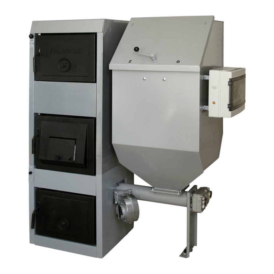
Positioning possibilities The boiler is equipped with the movable mains supply and plug. Boiler according to EN 60 335–1 ed. 2 Art. 7.12.4 must be positioned in such a way that the plug is accessible. Boiler positioning in the living space (including corridors) is prohibited! The installation of the boiler must comply with all requirements of ČSN 06 1008. - Page 12 Fig. no. 4 Boiler positioning in the boiler room Fig. no. 5 VULCANUS boiler (the right version with a small reservoir) with the open fuel reservoir...
-
Page 13: Hydraulic Connection Diagram
Hydraulic connection diagram Fig. no. 6 Hydraulic diagram with HW preparation– Pump heating circuit Fig. no. 7 Hydraulic diagram without HW preparation– Pump heating circuit Legend to Fig. no. 6 and 7: QAA 88 device Fuel feeder motor Safety thermostat Air fanmotor Boiler outlet temperature sensor Safety valve... - Page 14 Fig. no. 8 Hydraulic diagram with HW preparation– Mixing heating circuit Fig. no. 9 Hydraulic diagram without HW preparation– Mixing heating circuit Legend to figures no. 8 and 9: QAA 88 device Safety valve Safety thermostat Boiler primary circuit pump Thermostat HW Heating circuit pump Heating branch temperature sensor...
- Page 15 Note: Select the dimension of shorting pipe with stop valve V2 up to the half of other piping dimension. Shorting pipe is necessary. In case the thermostatic valve V1 is only closed through the boiler and mixing valve Y1 is open to the heating circuit the heating circuit with the heating circuit pump will be secured through this shorting pipe.
-
Page 16: Boiler Installation
Boiler installation Delivery and accessories VIADRUS HERCULES DUO boiler based on the order is delivered in such a way that the complete boiler drum including the basement is put on the pallet and packed boiler shell is gripped at the side of it. -
Page 17: Installation Procedure
HMI (ACX84.910/ALG) service unit for Saphir regulator operation – Siemens • Circuit pump UPS 25-40 • Water heater (see the VIADRUS a.s. offer) The optional boiler equipment is not included in the boiler standard price. Installation procedure 5.2.1 Installation of boiler drum with the basement Position the boiler drum with basement on the substructure (pad) into the horizontal position. - Page 18 Grate Deflector Hook Bottom ceramics Top ceramic plate Partition of the combustion space Partition of the combustion space- front Front ceramics Fig.No. 11 Location of components and ceramics inside the boiler...
-
Page 19: Shells Assembly
5.2.2 Shells assembly Fig. no. 12 Boiler shell... - Page 20 Mount the relevant connection accessories on the steel sheet components according to Fig. no. 12. Jacket the VULCANUS boiler according to Fig. no. 12. Screw the safety thermostat (2 pc screw M4 x 6) to the safety thermostat holder. Screw the holder with the safety thermostat to the left shell of basement (2 pc screw ST 4,8 x 13) –...
-
Page 21: Fuel Reservoir Assembly
5.2.3 Fuel reservoir assembly Fuel feeder Nut M6 (4 pcs) Stud bolt M10 x 30 (4 pcs) Fuel reservoir Washer 10,5 (4 pcs) 10. Screw M8 x 20 (4 pcs) Nut M10 11. Nut M8 (4 pcs) Ventilator 12. Washer 8,4 (8 pcs) Screw M6 x 16 (4 pcs) 13. -
Page 22: Mounting Of The Service Board To The Fuel Reservoir
Screw on the adjustable legs of the the fuel feeder assembly, see Fig.No. 13 - Detail D. Apply sealant onto the base of boiler , then mount the fuel feeder assembly to the base of the boiler and tighten. Thus we have ensured a precise position of the fuel feeder assembly perpendicularly to the boiler base. -
Page 23: Assembly Of The Emergency Fire Extinguishing Equipment
5.2.6 Assembly of the emergency fire extinguishing equipment In the cleaning hole cover there is a pipe for water inlet with 1/2“ connection that serves for BVTS valve or TS 130 or STS 20 interconnection. The interconnection can be carried out by means of flexible(stainless) hose. - Page 24 cutting off of the grate must be always toward the back wall at the frontal view into the boiler. In case of 5 - 7 sectional boiler size the cutting off of the grate must always be directed to entry to the fuel feeder.) ! ! ! ! Apply boiler mastic to the point...
- Page 25 Service board Nut M6 (4 pcs) Washer 6,4 (4 pcs) Screw M6 x 16 (4 pcs) Fuel reservoir Nut M8 (4 pcs) Washer 8,4 (8 pcs) Screw M8 x 20 (4 pcs) Fuel feeder 10. Screw M10 x 20 (4 pcs) 11.
- Page 26 Basement Nut M10 (10 pcs) Burner Blind flange Grate Insulation (sibral board) Screw M10 x 30 (6 pcs) Insulation of the opening otvoru (sibral mat) Washer 10,5 (16 pcs) 10. Holder (bracket) of insulation Fig. no. 17 Boiler conversion from the right-hand to left-hand design – dismantling of burner and blind flange On the left side part of the jacket of the base cut out a metal plate for the connection of the feeder.
- Page 27 Fig. no. 18 VULCANUS boiler (left-hand design)
-
Page 28: Wiring Diagram
5.2.8 Wiring diagram Single-phase circuit breaker 16A Fuel feeder motor Regulator Siemens ACX 38.030 Air fan motor Boiler output temperature sensor QAZ 36.526/109 Ventilator socket Temperature sensor HW QAZ 36.526/109 X10.1 Ventilator plug QAA 88 device Boiler primary circuit pump Fuel feeder temperature sensor QAZ 36.526/109 HW three-way valve Outside temperature sensor QAC 34/101... - Page 29 SERVICE SERVICE SAFETY THERMOSTAT Color of conduit: VENTILATOR SUPPLY Black VENTILATOR SPEED REGULATION Brown SERVICE FUEL FEEDER Blue BOILER PUMP GNYE Green-yellow HW THREE-WAY VALVE GREY Grey HW TEMPERATURE WHITE White BOILER OUTLET TEMPERATURE SERVICE YELOW Yellow FUEL FEEDER TEMPERATURE OUTSIDE TEMPERATURE ROOM DEVICE SERVICE...
- Page 30 Single-phase circuit breaker 16A K3, K4 Relay of the safety circuit Regulator Siemens ACX 38.030 Fuel feeder motor Heating branch temperature sensor QAD 36/101 Air fan motor Boiler output temperature sensor QAZ 36.526/109 Air fan motor socket QAA88 device X10.1 Ventilator plug Fuel feeder temperature sensor QAZ 36.526/109 Boiler primary circuit pump...
- Page 31 SERVICE INLET SERVICE SAFETY THERMOSTAT Color of conduit: VENTILATOR SUPPLY Black VENTILATOR SPEED REGULATION Brown SERVICE FUEL FEEDER Blue MIXING VALVE GNYE Green-yellow BOILER PUMP GREY Grey HEATING CIRCUIT PUMP WHITE White HW CHARGING PUMP YELOW Yellow SERVICE HEATING CIRCUIT TEMPERATURE HW TEMPERATURE (THERMOSTAT) BOILER OUTLET TEMPERATURE SERVICE...
-
Page 32: Boiler Operation By User
Boiler operation by user Control, regulation and security elements 6.1.1 Saphir regulator SAPHIR ACX 38 is the regulator destined for solid fuel boiler control, heating circuit control and hot water preparation by means of external reservoir control. The regulator is equipped with boiler sensor, hot water sensor or hot water thermostat (depending on the pump or mixing heating circuit), heating branch sensor (mixing heating circuit), sensor against the fire penetration and outside sensor. - Page 33 the fuel quantity is allocated adequately to the air volume. The boiler temperature increase against the heating branch desired temperature is 5 °C (set by the manufacturer). b) attenuation regime – after the requirement for heat has ceased the boiler goes over to the attenuation regime.
- Page 34 • QAA 88 device – space unit Space control • Outside sensorQAC34/101 – is not used • Thermostatic valve (Filling valve) - series VTC312 (external thread) or VTC 512 • Three-way valve V4044C (only in case boiler is used for HW heating) •...
- Page 35 • QAA 88 device – boiler unit Equithermal control without space effect • Outside sensor QAC34/101 • Thermostatic valve (Filling valve) - series VTC312 (external thread) or VTC 512 • Three-way mixing valve VBI31.20 with drive SQK34.00 • Heating branch sensor QAD36/101 •...
-
Page 36: Safety Thermostat
6.1.2 Safety thermostat The safety thermostat is mounted on the left-hand side part of basement shell and it serves for boiler shutdown in case the safety temperature has been exceeded. The safety thermostat must be set to 100 °C temperature i.e. to the temperature higher than the set maximum boiler temperature (90 C). - Page 37 Tab. no. 7 Parameters – Mixing heating circuit Set by the Resolution Parameter Description Units Range manufacturer Current outside temperature -20 … 50 Current boiler temperature 5 … 100 Current heating circuit temperature 5 … 100 Desired heating circuit temperature 0 …...
- Page 38 Set by the Resolution Parameter Description Units Range manufacturer P 104 Second period HC switched on [h:min.] 23:59 0:00 … 23:59 1 min. P 105 Second period HC switched off [h:min.] 23:59 0:00 … 23:59 1 min. Desired space temperature in the second P 106 10 …...
- Page 39 Set by the Resolution Parameter Description Units Range manufacturer Ventilator Y4 lignite – 4 sect. 40 … 70 Ventilator Y4 lignite – 5 sect. 30 … 80 P 167 Ventilator Y4 lignite – 6 sect. 30 … 85 Ventilator Y4 lignite – 7 sect. 30 …...
- Page 40 Set by the Resolution Parameter Description Units Range manufacturer Feeder Y2 pellets – 4 sect. 15 … 70 Feeder Y2 pellets – 5 sect. 15 … 70 P 213 Feeder Y2 pellets – 6 sect. 15 … 70 Feeder Y2 pellets – 7 sect. P 214 Feeder X3 pellets 8 …...
- Page 41 Tab. no. 8 Parameters – Pump heating circuit Set by the Resolution Parameter Description Units Range manufacturer Current outside temperature -20 … 50 Current boiler temperature 5 … 100 Desired heating circuit temperature 0 … 80 Current temperature HW 5 … 100 Desired boiler temperature in case of HW 0 …...
- Page 42 Set by the Parameter Description Units Range Resolution manufacturer P 111 Desired space temperature in attenuation 5 … 25 P 120 Setting the day of time schedule for HW 0 … 7 P 121 First period HW switched on [h:min.] 6:00 0:00 …...
- Page 43 Set by the Resolution Parameter Description Units Range manufacturer Feeder Y1 hard coal – 4 sect. 70 … 130 Feeder Y1 hard coal – 5 sect. 50 … 140 P 171 Feeder Y1 hard coal – 6 sect. 40 … 140 Feeder Y1 hard coal –...
- Page 44 Set by the Parameter Description Units Range Resolution manufacturer P 216 Feeder X4 pellets Feeder Y4 pellets – 4 sect. 4 … 26 Feeder Y4 pellets – 5 sect. 5 … 50 P 217 Feeder Y4 pellets – 6 sect. 5 …...
-
Page 45: Description Of Saphir Regulator Parameters
6.2.1 Description of SAPHIR regulator parameters Current outside temperature Current outside temperature displayed. The lowest displayed value of outside temperature is -20 Current boiler temperature Current boiler outlet temperature displayed. Current heating circuit temperature Current heating circuit temperature displayed Desired heating circuit temperature Current desired heating circuit temperature displayed Current temperature HW Current HW temperature displayed... - Page 46 Type of requirement (auto/fixed) Setting of the type of requirement for heating: By default there is used the auto – value 0 type of requirement. The boiler will heat automatically to the calculated desired water temperature. It is possible to use the fixed – value 1 type of requirement. The boiler will heat to the fixedly set outlet water temperature.
- Page 47 Boiler primary pump man/auto Setting of the pump control type. Man – manual pump run, Auto – automatic pump run according to P 50 current requirements. Value 0 – Man Value 1 – Auto Boiler primary pump off/on Primary pump switched on in case we have selected value 0 – Man on the line no.50. Value 0 –...
- Page 48 Day of warm water pump spinning On the determined day the pump spinning will be done at 12:00 h for 30 sec. Value 1 - 7 – corresponds to days from Monday to Sunday P 62 Value 0 – TV pump spinning is not active Value 8 –...
- Page 49 ECO automatics passive/active ECO function image. P 82 Value 0 – passive (the function is not active it means heating isn’t blocked) Value 1 – active (the function is active it means heating is blocked) Summer/winter temperature P 83 Setting the outside temperature at which the heating circuit requirement will be ignored. Note: The evaluation on the basis of average outside temperatures.
- Page 50 P 109 Desired space temperature in the third period Setting the desired space temperature in the third HC period P 110 HC time schedule reset By this parameter activation the time regime is reset into manufacturer’s setting. Value 1 – activation P 111 Desired space temperature in attenuation Setting the desired space temperature at the time outside the time period...
- Page 51 Feeder X2 lignite It regards the percentage value of output. P 152 The value 33 represents the 33% output and the feeder standstill time of parameter 153 is assigned to this value. Note: This parameter cannot be changed Feeder Y2 lignite (HU) P 153 Setting the feeder standstill time for HU fuel relating to 33% output Feeder X3 lignite...
- Page 52 Feeder Y1 hard coal(ČU) P 171 Setting the feeder standstill time for ČU fuel relating to 0% output Feeder X2 hard coal It regards the percentage value of output. P 172 Value 33 represents 33% output and feeder standstill time of parameter 173 is assigned to this value. Note: This parameter cannot be changed Feeder Y2 hard coal P 173...
- Page 53 P 210 Feeder X1 pellets It regards the percentage value of output. The value 0 represents min. output and feeder standstill time of parameter 211 is assigned to this value.Note: This parameter cannot be changed P 211 Feeder Y1 pellets Setting the feeder standstill time for pellets as the fuel relating to 0% output P 212 Feeder X2 pellets...
-
Page 54: Qaa 88 Device
P 228 Ventilator slowing-down in the attenuation regime– pellets Setting the ventilator slowing-down in the attenuation regime against the feeder runtime in the attenuation regime P 229 Ventilator output in the attenuation – pellets Setting the ventilator output in the attenuation regime P 232 Outside sensor deactivation The value 0 –... -
Page 55: Parameters Setting And Displaying
Fig. no. 24 Description of device QAA 88 Fig. no. 25 Connecting dimensions of device QAA 88 6.3.1 Parameters setting and displaying Parameters setting If you want to change parameters take following steps: • Press simultaneously the keys OK, ESC and – minus – blank display will appear. •... - Page 56 Parameters displaying If you only want to display the set parameters without the possibility to make any change take following steps: • Press simultaneously the keys OK, ESC a – minus – blank display will appear. • Press 2x key – minus and n0 appears on the display. •...
- Page 57 6.3.1.2 Fuel feeder and ventilator performance curve – hard coal – 4 sect. boiler size HARD COAL ČERNÉ UHLÍ Výkonová křivka podavače paliva (závislost podavače paliva na skutečném The fuel feeder performance curve (fuel feeder dependence on actual výkonu ventilátoru) ventilator output) The air fan performance curve (dependence of actual fan revolutions on Výkonová...
-
Page 58: Faults
6.3.2 Faults The faults are displayed by flickering display of QAA 88 device. Current fault number is displayed in P 15 parameter. In case more faults occur simultaneously first of all the fault with higher number will be displayed. The non-reversible fault 4 must be quitted after its elimination which is done on the introductory display of QAA device (i.e. -
Page 59: Service Board
FAULT MESSAGES IN CASE OF SHORT CIRCUIT OR SENSORS DISCONNECTION Heating branch temperature HC heating shut-down Boiler operation shut-down. Boiler outlet temperature protection against fuel fire penetration is active. Primary pump is active. HW reservoir temperature HW heating shut-down Feeder reservoir temperature Boiler operation shut-down. -
Page 60: Checking Activities Before Commissioning
Checking activities before commissioning Before the boiler is put into operation it is necessary to check: Filling the heating system with water Water for filling the boiler and heating system must be clear and colourless, without any suspended substances, oil and chemically aggressive substances. Its hardness must comply with ČSN 07 7401 and in case of dissatisfactory hardness the water must be trated. -
Page 61: Setting Of Parameters Before The Equipment Start-Up
Setting of parameters before the equipment start-up Parameters necessary for equipment start-up Before you make a fire you must set following parameters: Set by the Parameter Description Units manufacturer P 20 Fuel type P 238 Year P 239 Date P 240 Time These parameters are necessary for equipment start-up and other parameters can be modified as need may be or after the discussion with the technician. -
Page 62: Hmi (Acx84.910/Alg) Service Unit For Saphir Regulator Operation
ventilator is set to 50 % nominal ventilator output (set by the manufacturer). In case the fuel has changed for wood pellets this output must be set to 20 % (parameter P 22). − Maintain a sufficient height of fuel during making fire. −... -
Page 63: Superior Control
It is forbidden to use the flammable liquids for firing the VULCANUS boiler. • During the operation of VULCANUS boiler it is forbidden to overheat it in any way. • It is forbidden to put any objects made of flammable materials on the boiler and within a distance smaller than the safe distance from it. -
Page 64: Maintenance
• Having finished the heating season the boiler including the smoke flue must be thoroughly cleaned. The boiler must be kept clean and dry. • It is forbidden to interfere with construction and boiler electric installation. • In case the two-way safety device has responded to refill with water not conforming to ČSN 07 7401 it is necessary to treat the water in the system so that it again conforms to this standard. -
Page 65: Instructions For Product Disposal After Its Service Life
Instructions for product disposal after its service life VIADRUS a.s. is a contracting partner of the firm EKO–KOM a. s. with the client number F00120649. The packages comply with EN 13427. We recommend to dispose the packages in the following way:... - Page 66 Information for customer Packaging identification Assessment reference PE Plastic sacks, folie, corrugated board, iron and plastic fix line Identification of principal materials used. Paper, Polyethylene, iron, wood Part 1: Summary of assessment Standard/Report Assessment requirement Claim Note 1.1 Prevention by source reduction 1.2 Heavy metals and ensure below maximum permitted levels...
- Page 67 Heating boilers – Part 5: Heating boilers for solid fuele, hand and automatically stocked, nominal heat output of up to 300 kW – Terminology, requirements, testing and marking VIADRUS a.s. provides the guarantee: – For boilers 24 months after the boiler putting into operation, but maximum 30 months after the date it was dispatched from the manufacturing factory.
- Page 68 Annex to the guarantee certificate for customer- the user Record of accomplished guarantee and post-guarantee repairs and regular product checks Contracting service Record Customer´s Carried out activity organization date signature stamp, signature)
- Page 69 Heating boilers – Part 5: Heating boilers for solid fuele, hand and automatically stocked, nominal heat output of up to 300 kW – Terminology, requirements, testing and marking VIADRUS a.s. provides the guarantee: – For boilers 24 months after the boiler putting into operation, but maximum 30 months after the date it was dispatched from the manufacturing factory.
- Page 71 Heating boilers – Part 5: Heating boilers for solid fuele, hand and automatically stocked, nominal heat output of up to 300 kW – Terminology, requirements, testing and marking VIADRUS a.s. provides the guarantee: For boilers 24 months after the boiler putting into operation, but maximum 30 months after the date it was –...
- Page 72 Update: 17/2013 – GB - model 2013...
Need help?
Do you have a question about the VULCANUS and is the answer not in the manual?
Questions and answers