
Subscribe to Our Youtube Channel
Related Manuals for Viadrus HERCULES U 26


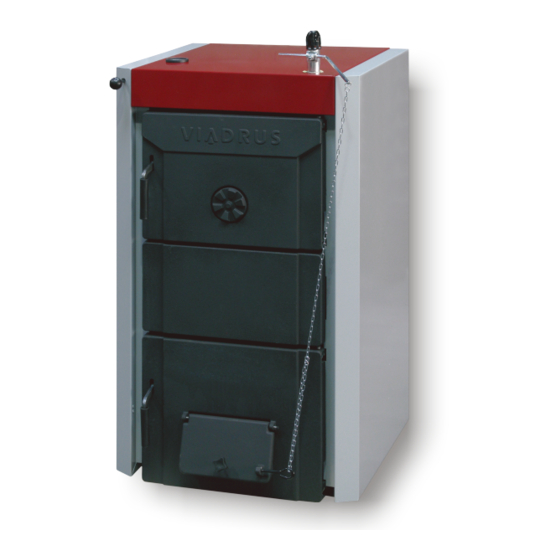
Summary of Contents for Viadrus HERCULES U 26
- Page 1 VIADRUS HERCULES U 26 Hercules U26 MANUAL FOR BOILER OPERATION Návod k obsluze AND INSTALLATION...
-
Page 2: Table Of Contents
Table of contents: page Boiler use and advantages ........................3 Boiler technical data ..........................3 Description ............................... 8 Boiler construction ..........................8 Regulation and safety elements ......................8 Equipment for surplus heat removal ....................11 Superfluous heat removal equipment- storage reservoirs ............... 13 Positioning and installation ........................ -
Page 3: Boiler Use And Advantages
Dear customer We thank you that you have bought VIADRUS HERCULES U 26, a universal boiler thus having shown your confidence in VIADRUS a.s.. For you to get used to a correct way of handling your new product from the beginning please read at first this manual for its usage (first of all the chapter no. - Page 4 Tab. no. 2 Dimensions, technical parameters –coke as fuel granularity 24 – 60 mm, fuel moisture max. 15 % fuel efficiency: 26 - 30 MJ.kg Number of sections Rated power 22,5 37,5 43,5 Fuel consumption at the rated kg/h 2,43 3,64 4,86 6,07...
- Page 5 výkon kotle [kW] Rated power (kW) Fig. No. 1 Hydraulic loss of the boiler drum 7 - 8 Actual stack height [m] Účinná výška komínu [m] Fig. No. 2 Stack diameter setting...
- Page 6 Number of sections 1087 Fig.no.3a) Connecting dimensions of VIADRUS HERCULES U 26 3 – 7 sect. boiler...
- Page 7 Number of sections 1053 1164 1198 1309 1420 Fig. no. 3b) Connecting dimensions of VIADRUS HERCULES U 26 8 – 10 sect. boiler.
-
Page 8: Description
Description Boiler construction The main part of boiler is the cast-iron sectional boiler drum made of the grey cast-iron according to EN 1561, quality 150. The pressure parts of boiler meet the demands on the strength according to: EN 303-5 Heating boilers –... - Page 9 25. Bushing HEYCO 12. Outlet neck 26. Slant bushing 13. Return water flange 27. Plastic ball 14. Filling and draining cock 28. Label for smoke flap control Fig. no. 4a) VIADRUS HERCULES U 26 3 – 7 sect. boiler assembly...
- Page 10 30. Choker for the rear section 15. Lowered console 31. Choker axis for the rear section 16. Upper part of the shell with insulation 32. Right choker console for the rear section Fig. no. 4b) VIADRUS HERCULES U 26 8 – 10 sect. boiler assembly.
-
Page 11: Equipment For Surplus Heat Removal
4 – additional grate (3 – 10 sect.) Fig.no.4c) Diagram of VIADRUS HERCULES U 26 boiler - location of additional equipment Equipment for surplus heat removal The after-cooling loop or the two way safety vent DBV 1 - 02 serves for surplus heat removal in case the water temperature in boiler exceeds 95 °C. - Page 12 A – cold water inlet B – output to boiler C – output to drain D – input from boiler Fig. No. 6 The two way safety vent DVB 1 - 02 1 – Boiler 7 – Pump 2 – Two way safety vent DBV 1 – 02 8 –...
-
Page 13: Superfluous Heat Removal Equipment- Storage Reservoirs
Installation Installation can be only carried out by a qualified person. For the correct operation of the thermostatic, two ways safety vent it is necessary to comply with the conditions for its installation and keep the flow directions marking on its body. The safety vent is always mounted in the output pipe of boiler or directly on the upper part of boiler, where the hot water leaves boiler and is transported into heating system. -
Page 14: Positioning And Installation
Positioning and installation Regulations and guidelines The solid fuel boiler can only be installed by a firm holding a valid licence to carry out its installation and maintenance. A project according to the valid regulations must be elaborated for installation. Before the boiler installation on an older heating system the installation firm must flush out(clean) the whole system.The heating system must be filled with water meeting the ČSN 07 7401 requirements;... - Page 15 number of sections L mm] 1053 1164 Fig. No. 9 Substruction (retaining wall) dimensions Tab. no. 5 Grade of reaction to fire Examples of building materials and products included in the reaction to fire Grade of reaction to fire (Extract from EN 13 501-1 + A1) A1 –...
-
Page 16: Delivery And Assembly
Delivery and assembly Delivery and accessories Boiler is delivered according to the purchase order on the pallet on which the complete boiler drum is placed and on the side there is attached the wrapped boiler shell. The accessories are put inside the boiler drum, accessible only after opening the stoking door. -
Page 17: Assembly Procedure
By request (is not included in delivery): • Filter 3/4“ – for delivery with the two way safety vent DBV 1 - 02 The supplementary outfit, necessary accessories and optional boiler accessories is not included in the boiler standard price. Assembly procedure 5.2.1 Installation of smoke extension (only for the size of 8 –... - Page 18 Blind the threaded opening JS 6/4“ in the front section with JS 6/4“ plug. Insert the sealing Ø 60 x 48 x 2 under the plug. 10. It is recommended to use shut-off valves for heating water inlet and outlet since without the valves it will be necessary to drain the whole system during the filter cleaning.
-
Page 19: Boiler Shells Assembly
5.3.3 Boiler shells assembly Take the shells out of the cardboard cover. Put two lowered consoles(1) on the threads of upper anchor bolts and screw them by means of four nuts M10 (3) and four washers 10,5 (2) - (see Fig.no.13). Lowered console (2 pc) Washer 10,5 Nut M10... - Page 20 Mount two spring clips (2) on the right side part of the shell (1), then insert the insulation (see Fig.no.14). Put the boiler shell on the lower anchor bolts and connect the upper part with the lowered consoles by means of two screws M5 x12 and two washers 6,4 (see Fig.no.17). Mount two spring clips (2) on the left side part of the shell (1), insert the bushings (3, 4), then insert the draw bar of smoke flap control (5) and the insulation (see Fig.no.15).
-
Page 21: Mounting Of Draw Bar Of Smoke Flap Control
1. Right side part of the shell 7. Draught controller 2. Washer 5,3 8. Thermomanometer 3. Screw M5 x 10 9. Upper part of the shell 4. Left side part of the shell 10. Rear part of the shell 5. Screw M5 x 10 11. -
Page 22: Draught Regulator
Smohe adapter with the smoke flap Choker screw Draw bar of the smoke flap control Suspension pin Lock 2,5 x 32 Lever of the draught controller Plastic ball M10 Chainlet Label of the smoke flap control Fig.no.18 Smoke flap control 5.2.5 Draught regulator The instructions for the draught regulator setting are given in the manual attached to the particular regulator. -
Page 23: Commissioning
Commissioning The boiler can only be commissioned by professional assembly firms authorized to do this activity. Verification activities before commissioning Before the boiler is put into operation it is necessary to check: Filling the heating system with water (thermomanometer check) and the system tightness. Connection to the chimney–... -
Page 24: Important Warning
On the flaring wood load a thinner layer of basic fuel. After its good ignition load other fuel up to the lower edge of the stoking door and level the fuel into a uniform layer along the whole depth of the boiler. 10. -
Page 25: Maintenance
Instructions for product disposal after its lifetime extinction VIADRUS a.s. is a contracting partner of the firm EKO–KOM a. s. with the client number F00120649. The packages comply with EN 13427. We recommend to dispose the packages in the way as follows:... -
Page 26: Guarantee And Reliability For Defects
The user is obliged to entrust a professional assembly firm with the commissioning and a contractual professional service accredited by VIADRUS a.s., the manufacturer with the removal of faults. Otherwise the guarantee for boiler proper function does not apply. „VIADRUS HERCULES U 26 boiler quality and completeness certificate“... - Page 27 Information for customer Packaging identification Assessment reference PE Plastic sacks, folie, corrugated board, iron and plastic fix line Identification of principal materials used. Paper, Polyethylene, iron, wood Part 1: Summary of assessment Standard/Report Assessment requirement Claim Note 1.1 Prevention by source reduction 1.2 Heavy metals and ensure below maximum permitted levels...
- Page 29 Annex to the guarantee certificate for customer- the user Record of accomplished guarantee and after-guarantee repairs Contractual professional Record Customer ´s Carried out activity service organization date signature (stamp, signature)
- Page 32 Date of revision 17/2013 – GB – model 2010...
Need help?
Do you have a question about the HERCULES U 26 and is the answer not in the manual?
Questions and answers