
Related Manuals for Viadrus ules U26


Summary of Contents for Viadrus ules U26
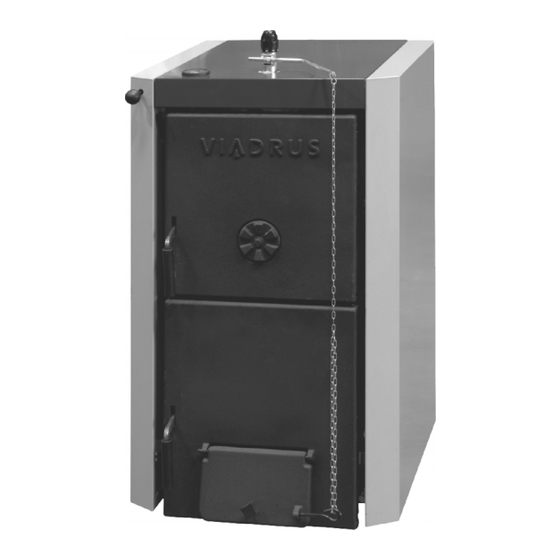
- Page 1 VIADRUS U 22 C/D Hercules U26 MANUAL FOR BOILER OPERATION Návod k obsluze AND INSTALLATION...
-
Page 2: Table Of Contents
Contents: page 1. Usage and advantages of the furnace ......................3 2. Technical data of the furnace VIADRUS U 22 .................... 3 Section number ............................3 3. Description..............................5 3.1 Construction of the furnace ........................5 3.2 Regulating and security elements ......................5 4. -
Page 3: Usage And Advantages Of The Furnace
800 kPa. The VIADRUS U 22 D furnace is different from the VIADRUS U 22 C furnace version by its enlargement of the stoke hole so that it is possible to burn even bigger clogs up to the average of 220 mm. By burning wooden logs the heat work difficulty is considerably reduced and the service quality is increased. - Page 4 Chart Nr.2 Dimensions, technical parameters of the furnace VIADRUS U 22 D Section number pieces Weight Water space volume 36,2 40,9 45,6 50,3 55,0 59,7 64,4 Firing chamber volume Firing chamber depth Lightness of the stove - pipe Furnace dimensions: - height x width...
-
Page 5: Description
There are barriers of the smoky channel between the front and medium sections above the stoker hole of the furnace VIADRUS U 22 C. It serves for reducing the draw – away cross - section and for a better... - Page 6 (2 – 5 sectional). They are used with a various cross – section width according to the sizes of the furnaces in conformity with this chart: Chart Nr.7 Barriers of the smoky channel of the VIADRUS U 22 C furnace Furnace section Cross –...
- Page 7 2. Middle section with a cutout 3. Middle section with a strip 4. Rest section 5. Plug 6. Insert 7. Anchor bolt 8. Sealing 9. Clack valve of the thermomanometer 10. Thermostat well Fig. no. 3 Diagram of VIADRUS HERCULES U 22 D boiler drum...
- Page 8 16. Blind flange 19 17. Blind flange 15,9 18. Washer 10,5 19. Nut M10 20. Washer 5,3 21. Screw M5 x 12 22. Lock 2,5 x 20 Fig. no. 4 Assembly of VIADRUS HERCULES U 22 boiler with the box...
- Page 9 13. Filling and draining cock 14. Thermomanometer 15. Bushing HEYCO 16. Blind flange 19 17. Blind flange 15,9 18. Washer 10,5 19. Nut M10 20. Lock 2,5 x 20 Fig. no. 5 Assembly of VIADRUS HERCULES U 22 boiler without the box...
-
Page 10: Placing And Installation
Heating systems in buildings – Safety devices. ČSN 73 6660 House water plumbing 4.2 Placing possibilities The VIADRUS U 22 furnace is approved for installation in non – residential spaces (for example – (cellar, corridor, etc.) Section number A [mm]... - Page 11 Furnace placing with regard to fire regulations: 1. Placing on floor of flame resistant material (Pic.6) furnace to be put on a flame resistant backing exceeding the furnace platform over 20 mm at sides and only on the boiler drum depth. if the furnace is situated in a cellar we recommend to place it on a bedding of minimum 50 mm height.
-
Page 12: Order, Delivery And Assembly
5.2 Delivery and accessories The VIADRUS U 22 furnace is delivered according to the order in a manner that a complete boiler drum is located on the palette and a covered boiler jacket is fixed on the side. The accessories are stored inside the boiler drum and is available after opening the stoker hole. -
Page 13: Assembly Techniques
5.3 Assembly techniques Fig.no. 8 Connecting dimensions of VIADRUS HERCULES U 22 boiler without the control box Fig.no. 9 Connecting dimensions of VIADRUS HERCULES U 22 boiler with the control box... -
Page 14: Boiler Drum Installation
5.3.1 Boiler drum installation 1. Put the boiler drum on an embedding. 2. Put a sealing φ 90 x 60 x 3 on the upper flange part of the back section and fix the flange of the heat water. The flange to be welded to the distribution of the heat water in advance. 3. -
Page 15: Jacket Assembly
5.3.2 Jacket assembly Mounting of the side part of the jacket and the rear part of the jacket Remove the jackets from the cardboard cover. Put the consoles 1 (1) and 2 (4) on the thread of the right upper anchor screw and screw them by means of two nuts M10 (6) and two washers 10,5 (5) - (see Fig. - Page 16 5. Mount two connecting plugs (5), into the left side part of the jacket (1), insert the bushings (2, 3), then insert the draw bar of the smoke flap control (4) and the insulation. Put the jacket on the lower anchor bolts and connect the upper part with consoles 1 and 2 by means of two screws M5 x12 and two washers 5,3 –...
- Page 17 Right side part of the jacket Thermomanomater Screw M5 x 12 Rear part of the jacket Washer 5,3 10. Screw ST 4,2 x 9,5 Left side part of the jacket 11. Bushing HEYCO Screw M5 x 12 12. Slant bushing Washer 5,3 13.
- Page 18 Mounting of the upper part of the jacket in case of the boiler with the control box(see Fig.no.16): 1. Connect the front and rear part of the lower part of the control box by means of two consoles (2) and four screws M5 x 10 (3).
- Page 19 1. Right side part of the jacket 11. Upper part of the control box 2. Screw M5 x 12 12. Screw M 5 x 12 3. Washer 5,3 13. Thermomanometer 4. Left side part of the jacket 14. Rear part of the jacket 5.
- Page 20 1 – Smoke adapter with the smoke flap 5 – Screw of choker 2 – Smoke flap control draw bar 6 – Suspension plug 3 – Lock 2,5 x 20 7 – Draught controller 4 – Plastic ball M10 8 – Label of smoke flap control Fig.
-
Page 21: Putting Into Operation - Instructions For A Contractual Service Organization
6. Putting into operation – instructions for a contractual service organization Putting the furnace into operation can be performed only by a contractual service organization authorized for performing of this operation. 6.1 Control operation before starting Before starting the furnace it is needed to check: a) filling the heat system with water (thermomanometer check) and system tightness. -
Page 22: Important Notice
Heating up 1. Check the water volume in the heat system on the thermomanometer. 2. Open the closing armatures between the furnace and the heat system. 3. Clean out the grate, ashtray, smoky channels and furnace walls. 4. Spread out the kindling through the ash door with the stoker – hole on a cleaned grate along its entire depth. -
Page 23: Maintenance
6. Using of flammable liquids is DISALLOWED for firing the VIADRUS U 22 C furnace. 7. It is DISALLOWED to overheat the furnace during its operation. -
Page 24: Warranty And Defect Liability
If the furnace is operated according to the instructions mentioned in the “Instructions for the furnace operation and installation”, the furnace does not require any special professional service interventions. “Certification of the quality and completeness of the VIADRUS U 22 furnace” serves for filling in by a contractual service organization as the ”Warranty card”. - Page 25 Information for customer Packaging identification Assessment reference PE Plastic sacks, folie, corrugaled board, iron and plastic fix line Identification of principal materials used. Paper, Polyethylene, iron, wood Part 1: Summary of assessment Standard/Report Assessment requirement Claim Note 1.1 Prevention by source reduction 1.2 Heavy metals and ensure below maximum permitted...
Need help?
Do you have a question about the ules U26 and is the answer not in the manual?
Questions and answers