
Related Manuals for Viadrus HERCULES U28


Summary of Contents for Viadrus HERCULES U28
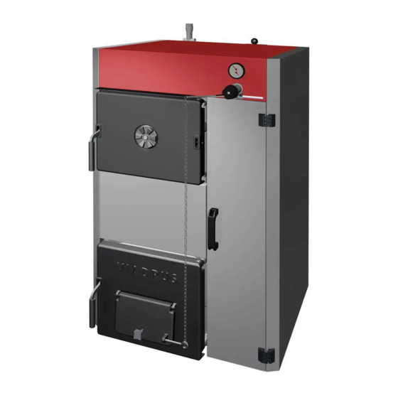
- Page 1 VIADRUS HERCULES U28 Manual for boiler operation and installation GB_2015_21 GB_2016_48...
-
Page 2: Table Of Contents
Table of contents page Technical information ............................3 Usage ................................3 Boiler advantages ............................3 Boiler technical data ............................4 Basic boiler dimensions ..........................5 Assembly manual ..............................7 Boiler construction ............................7 Rules and directives ............................7 Positioning possibilities ..........................8 Delivery and accessories .......................... -
Page 3: Technical Information
Technical information VIADRUS HERCULES U28 is cast-iron low-pressure boiler designed for combustion of solid fuels – light coal and hard coal. As a complement fuel it is possible to use wood. -
Page 4: Boiler Technical Data
Boiler technical data Tab. №. 1 Dimensions, technical data Number of sections Boiler class according to EN 303 - 5 Combustion chamber volume 45,6 61,9 78,2 94,9 Water space volume 52,6 71,7 81,3 Weight Combustion chamber depth Diameter of smoke socket Boiler dimensions: height x width 1165 x 695 depth L... -
Page 5: Basic Boiler Dimensions
Basic boiler dimensions 1053 1164 Fig. №. 2 Basic boiler dimensions... - Page 6 Front cell 14 Draught regulator Center cell 15 Pipe of output water Middle section without lower bar 16 Filling and cock Rear cell 17 Pipe of input water Feeding gate (with the rosette of primary air) 18 Two-way safety cock DBV 1 - 02 Cleaning cover -upper 19 Safety valve Cleaning cover - lower...
-
Page 7: Assembly Manual
Assembly manual Boiler construction The main boiler part is the cast-iron sectional boiler drum made of the grey cast-iron according to EN 1561, quality 150. The pressure parts meet the strenght demands according to EN 303- 5. The boiler drum is assembled of sections by means of pressed boiler nipples with 56 mm diameter and secured by anchor bolts. -
Page 8: Positioning Possibilities
Positioning possibilities Boiler positioning in the living space (including corridors) is prohibited! The installation of the boiler must comply with all requirements of ČSN 06 1008. Permanent access of air must be ensured in the room where the boiler will be installed and operated. Boiler positioning with regard to the fire regulations: 1. - Page 9 Boiler positioning with regard to the necessary handling space: • Basic environment AA5/AB5 according to ČSN 33 2000-1 ed. 2. • In front of the boiler there must be left a minimum handling area of 1000 mm. • The minimum distance between the rear part of boiler and the wall 400 mm. •...
-
Page 10: Delivery And Accessories
Delivery and accessories The boiler is packed in a transport package and must not be tilted over during the transport. The accessories are put inside the boiler drum, accessible by opening the stoking door. Standard Boiler Delivery: • Boiler with appropriate number of sections on a pallete •... - Page 11 Necessary accessories: (they are not included in delivery): • Two-ways safety valve DBV 1 – 02 (1 pc) incl. siesal (10 g); this equipment has not to be used in case of open heating system • Safety valve – 1 pc By request (is not included in delivery): •...
-
Page 12: Assembly Technique
Assembly technique 2.5.1 Installation of the boiler body Fit the boiler drum on the retaining wall (substruction). Mount to the boiler drum system outlet the connecting tube G 1 1/2“. It must be connected by means of a removable joint to the heating system. Mount to the boiler drum system outlet the connecting tube G 1 1/2“. - Page 13 15. To fit on the draught regulator the pull rod with chain let (in accordance with attached Manual of draught regulator). Left side part of cover with insulation (2 pcs of connecting pin) Right side part of cover with insulation and front part of cover (2 pcs connecting pins, 2 pcs door hinges, 8 pcs M4 x 6 screws, 8 pcs 4,3 washers) Middle part of cover (4 pcs spring leave retainers, 1 pc magnetic element, 1 pc M5 nut) Small ash pan with removable cover (1 pc removable cover, 1 pc 4,3 washer, 1 pc M4 butterfly nut)
- Page 14 Left side part of cover with insulation Pull rod of smoke control (2 pcs connecting pins, 2 pcs M5 x 12 screws, (2 pcs cotter pins, 2 pcs 10,5 washers, 2 pcs 5,3 washers) 1 pc M10 nut) Right side part of cover with insulation 10 Console of cover (2 pcs connecting pins, 2 pcs M5 x 10 screws, (4 pcs M10 nuts, 4 pcs 10,5 washers)
- Page 15 Fig. №. 9 Boiler Cover Note: Before stoking it is necessary to open the partition in smoke adaptor by means of the pull rod of smoke control. Thus the flue gases are discharged through the shorting opening into the chimney.
-
Page 16: Way Of Positioning Of Side Grate In Boiler
2.5.3 Way of Positioning of Side Grate in Boiler Section Grate Head Metal Fig. №. 10 Position of Side Grate in Boiler Side grate will be positioned in the boiler under the angle of about 45 ° between 4 and 5 section grate head metal, see the detail in Fig. - Page 17 Boiler 4 sections Boiler 5 sections Boiler 6 sections Boiler 7 sections Side grate 4 sections Side grate 5 sections Side grate -additive Fig. №. 11 Positions of Side Grates in Individual Sizes of Boiler (Coal fuel) Side grates serve for combustion of coal fuel. If addtitive fuel of timber is combusted, take off these grates from the boiler.
-
Page 18: Change Of Opening Direction Of Stocking Door
2.5.4 Change of Opening Direction of Stocking Door 1. Raise the upper part of cover (13). 2. Disassemble the stocking door (1) by taking 2 pcs of door pins off (7). 3. Remove 2 pcs of M10 x 55 screws (4) including 2 pcs of M10 nuts (5) and 2 pcs of 10,5 washers (6) into the head metals on the left side. -
Page 19: Filling The Heating System With Water
2.5.6 Filling the heating system with water The water hardness must correspond to ČSN 07 7401 and it is inevitable to treat the water according to Chap. no. 2.2. in case the water hardness is unsatisfactory. The heating systems with an open expansion tank allow the direct contact between the heating water and the atmosphere. - Page 20 Fig. №. 13 Stocking Door Rosette for Primary Air Supply The rosette in the boiler back part stays closed. If smoke comes out the chimney, the rosette may be opened a little bit. By that more tertiary air is admitted into the boiler. The suffocating throttle of ash pan door controls inlet of secondary combustion air under the boiler grate.
-
Page 21: Equipment For Surplus Heat Withdrawal
Equipment for surplus heat withdrawal The two way safety vent DBV 1 - 02 serves for surplus heat removal in case the water temperature in boiler exceeds 95 °C. In case the system is equipped with a two way safety vent and the boiler becomes overheated (the output temperature exceeds 95 °C) the two way safety vent creates a cold water circuit which is kept until the temperature drops below the limit temperature. - Page 22 1 – Boiler 7 – Pump 2 – Two way safety vent DBV 1 – 02 8 – Surplus heat removal 3 – Safety valve 9 – Bleed valve 4 – Transforming valve I – Cooling water inlet 5 – Filter II –...
-
Page 23: Equipment For Heat Exhausting - Accumulating Reservoir
ATTENTION! Failure of it will cause extreme pollution of the boiler drum. Hydraulic schemes of the boilers with an accumulating reservoir are at disposal in the project materials of Viadrus at www.viadrus.cz. -
Page 24: Firing
▶ Follow the instructions for operating the boiler. ▶ When operating the boiler follow the recommended operating temperature. ▶ Operate the boiler with an approved fuel. primary air secondary air III. tertiary air open–Lighting fire/Stocking closed - Operation III. III. Fig. -
Page 25: Operation
Fig. №. 19 Scheme of flue gas passage through the boiler Operation 1. After having achieved the heating water temperature regulate the combustion air inlet. Power control is executed by the suffocating throttle that regulates secondary air inlet under the grate by means of the damper or by the adjusting screw of the suffocating throttle itself. -
Page 26: Boiler Cleaning - Maintenance
Boiler cleaning - maintenance 1. Ash from ash pan and small ash pan has to be removed in the boiler operation even several times a day according to the type of used fuel, because full ash pan protects the correct division of the combustion air under fuel and evokes rough burning of fuel on grate. -
Page 27: Important Notice
Insulation of the cleaning covering of the smoke extension part Cleaning covering of the smoke extension piece Washer 5,3 Screw with the hexagon head M5 x 14 Fig. №. 21 Cleaning of the smoke extension piece IMPORTANT NOTICE The boiler only can be used for the purpose that it is destined for. The boiler can be operated only by adult persons acquainted with this operation manual. -
Page 28: Instruction For Product Disposal After Its Service Life
If you fail to meet these conditions you cannot requisite the guarantee repairs. Instruction for product disposal after its service life VIADRUS a.s. is a contracting partner of the firm EKO–KOM a.s. with the client number F00120649. The packages comply with EN 13427. -
Page 29: Guarantee And The Liability For Defects
Guarantee and the liability for defects VIADRUS a.s. provides the basic guarantee period during 24 months from the sell-by date, but not longer than 30 months from the dispatch date of the product from the production plant. The condition for validity of the guarantee is observation of instructions for mounting, mainly as following: •... - Page 30 Information for customer Packaging identification Assessment reference PE Plastic sacks, folie, corrugated board, iron and plastic fix line Identification of principal materials used. Paper, Polyethylene, iron, wood Part 1: Summary of assessment Standard/Report Assessment requirement Claim Note 1.1 Prevention by source reduction 1.2 Heavy metals and ensure below maximum permitted levels...
- Page 31 Annex to the guarantee certificate for customer- the user Record of accomplished guarantee and post-guarantee repairs and regular product checks Contracting service Record Customer´s Carried out activity organization date signature (stamp, signature)
- Page 32 VIADRUS HERCULES U28 VIADRUS a.s. Bezručova 300 | CZ - 735 81 | Bohumín E-mail : info@viadrus.cz | www.viadrus.cz...
Need help?
Do you have a question about the HERCULES U28 and is the answer not in the manual?
Questions and answers