Table of Contents
Advertisement
Quick Links
BPI-G1 Software
Table of Contents
1.1
1.2
1.2.1
1.2.1.1
1.2.1.2
1.2.1.3
1.2.1.4
1.2.1.5
1.2.1.6
1.2.1.6.1
1.2.1.6.2
1.2.1.7
1.2.1.8
1.2.1.9
1.2.2
1.2.2.1
1.2.2.2
1.2.2.3
1.2.2.4
1.2.3
1.2.3.1
1.2.3.2
1.2.4
1.2.5
1.3
1.3.1
1.3.1.1
1.3.1.2
1.3.1.3
1.3.1.4
1.3.2
1.4
1.5
1.5.1
1.5.2
1.6
1.7
1
Advertisement
Table of Contents

Subscribe to Our Youtube Channel
Related Manuals for Banana Pi BPI-G1


Summary of Contents for Banana Pi BPI-G1
-
Page 1: Table Of Contents
Table of Contents About BPI-G1 IoT development board BPI-G1 hardware BPI-G1 hardware interface 1.2.1 STM32F103CB part Peripheral Interface 1.2.1.1 TI CC3200 part Peripheral Interface 1.2.1.2 TI CC2530 part Peripheral Interface 1.2.1.3 TI CC2540\/1 part Peripheral Interface 1.2.1.4 Global Power and Ground 1.2.1.5 Module interconnection 1.2.1.6 CC2540 connection with F103 1.2.1.6.1 CC2530 connection with F103 1.2.1.6.2 TI CC3200 mode selection jumper 1.2.1.7 Status LEDs for each module 1.2.1.8 Button 1.2.1.9 BPI-G1 Hardware Specifications 1.2.2 The features TI CC3200 1.2.2.1 The features TI CC2530 1.2.2.2 The features TI CC2540\/1 1.2.2.3 The features STM32F103CB 1.2.2.4 BPI-G1 Main features 1.2.3 Which IDE development can use 1.2.3.1... -
Page 3: About Bpi-G1 Iot Development Board
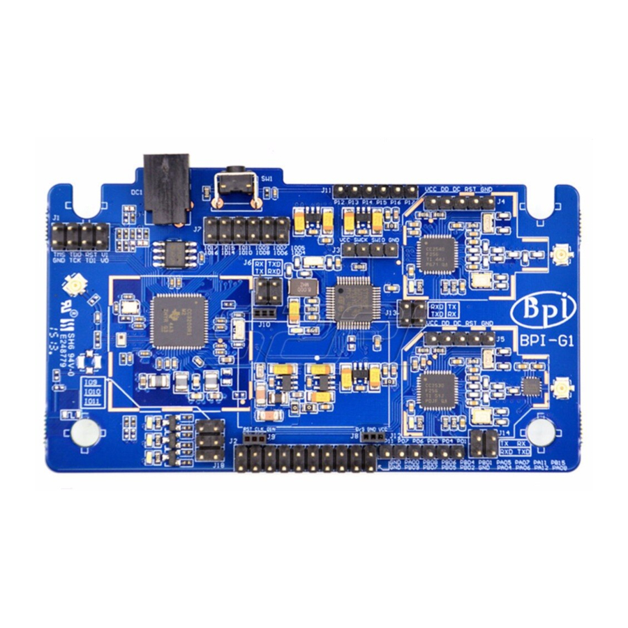
About BPI-G1 IoT development board About BPI-G1 IoT development board BPI-G1 is an integrated IEEE802.11 b / g / n (WIFI wireless network), IEEE802.15.4 (Zigbee), IEEE 802.11-2007 Standard (Bluetooth Low Energy4.0) development board. It is very easy to put these wireless protocol seamlessly together, you can exchange any different transport protocols, and three kinds of wireless protocols are integrated by three single-chip SOC, you can easily create your own Internet of things (IoT). WIFI part of which is the use of TI's CC3200, which is a high- performance ARM® Cortex®-M4 wireless SOC, internally integrated TCP / IP protocol stack, simply use the BSD Socket can connect to the Internet. The Zigbee is used TI CC2530, which integrates wireless capabilities and enhanced 8051 core SOC, TI after years of improvement, it is already quite mature and stable, TI's Z-stack has achieved Zigbee 2007 / Pro, you can use the 16's short address, you can use the 64-bit long address communication, face large local interconnect systems, advanced security encryption and mesh network structure can easily cope. Bluetooth 4.0 (BLE) using TI CC2540 / 1, an integrated BLE stack and enhanced 8051 core, low-power wireless SOC, at present, most mobile phones have support for Bluetooth 4.0, both as a wearable device, or mobile interactive Accessories, CC2540 can be easily completed. Meanwhile BPI G1 also incorporates a high-performance STM32 ARM® Cortex®-M3 microcontroller, which will help you deal with time-consuming data or transit, the three wireless SOC coordinated. Therefore, the use of BPI G1 can help you quickly achieve a variety of things DIY design. What can I do with BPI-G1? 1. Smart Home. 2. Intelligent Gateway 3. DIY electronic control... -
Page 4: Bpi-G1 Hardware
BPI-G1 hardware BPI-G1 hardware... -
Page 5: Bpi-G1 Hardware Interface
BPI-G1 hardware interface BPI-G1 hardware interface... -
Page 6: Stm32F103Cb Part Peripheral Interface
STM32F103CB part Peripheral Interface STM32F103CB part Peripheral Interface Uart Interface SPI Interface I2C Interface... - Page 7 STM32F103CB part Peripheral Interface CAN Interface USB2.0 Interface PWM & Timer Capture channel...
- Page 8 STM32F103CB part Peripheral Interface ADC channel...
-
Page 9: Ti Cc3200 Part Peripheral Interface
TI CC3200 part Peripheral Interface TI CC3200 part Peripheral Interface 4-wire SDIO Interface Uart Interface SPI Interface... - Page 10 TI CC3200 part Peripheral Interface I2C Interface PWM & Timer Capture channel...
- Page 11 TI CC3200 part Peripheral Interface ADC channel...
-
Page 12: Ti Cc2530 Part Peripheral Interface
TI CC2530 part Peripheral Interface TI CC2530 part Peripheral Interface Uart Interface SPI Interface PWM & Timer Capture channel... - Page 13 TI CC2530 part Peripheral Interface ADC channel...
-
Page 14: Ti Cc2540/1 Part Peripheral Interface
TI CC2540\/1 part Peripheral Interface TI CC2540/1 part Peripheral Interface Uart Interface SPI Interface ADC channel... - Page 15 TI CC2540\/1 part Peripheral Interface PWM & Timer Capture channel...
-
Page 16: Global Power And Ground
Global Power and Ground BPI-G1 Global Power and Ground... -
Page 17: Module Interconnection
Module interconnection BPI-G1 Module interconnection WIFI (CC3200), BLE (CC2540 / 1) and ZIGBEE (CC2530) are interconnected through STM32F103CB serial port, they can work alone, can also coordinate the work will be given below communication connections between the modules schematic。5.1 CC3200 connection with F103... -
Page 18: Cc2540 Connection With F103
Module interconnection CC2540 connection with F103... -
Page 19: Cc2530 Connection With F103
Module interconnection CC2530 connection with F103... -
Page 20: Ti Cc3200 Mode Selection Jumper
TI CC3200 mode selection jumper TI CC3200 mode selection jumper Programming mode Under the programming mode, you need to VI and VO short on power, CC3200 will receive as a writer, it will be the serial data received by the SPI mode file system writes to the external SFLASH, but the programming is completed after not running, you need to disconnect VI and VO, then on again, then it will be read in the file system SFLASH into memory and execute code. As shown in Figure. Run mode Run mode, you need to disconnect VI and VO, then power on, CC3200 will SFLASH read from the file system into memory and run. In this mode, plug in the JTAG interface, using the IDE's DEBUG function, and the code will be downloaded from the JTAG interface to the memory to run, you can perform single-step debugging. For fast functional verification, this is the fastest way. However, after a reset circuit, CC3200 will be new to SFLASH read the file system operation. As shown in Figure. - Page 21 TI CC3200 mode selection jumper...
-
Page 22: Status Leds For Each Module
Status LEDs for each module Status LEDs for each module... -
Page 23: Button
Button Button BPI G1 has a button, which is connected to the PB3 pin F103, in the middle of a pullup resistor in parallel, when the key is pressed, the pin will be low-level information. Figure. -
Page 24: Bpi-G1 Hardware Specifications
BPI-G1 Hardware Specifications BPI-G1 Hardware Specifications Items Hardware Specifications STM32F103CB ARM Cortex™- M3 32-bit RISC core CC3200 device is an integrated high-performance ARM Cortex-M4 MCU and with a Wi-Fi network processor subsystem (This subsystem includes 802.11 b / g / n radio, baseband, network WIFI protocol stack and a powerful encryption engine MAC, supports 256-bit encryption in order to achieve a fast, secure Internet connection). This device contains a variety of peripherals, I2S, SD / MMC, UART, SPI, I2C and four-channel analog to digital converter (ADC). CC2540 device is a low cost, low power, true system-on-chip (SoC) for Bluetooth low energy applications. It enables to build a strong BLE master or slave node with very low total cost BOM. Bluetooth The CC2540 combines the excellent RF transceiver, the industry-standard enhanced 8051 MCU, in-system programmable flash memory, 8 KB RAM and many other powerful auxiliary functions and peripherals. CC2530 device is a true system-on-chip (SoC) for IEEE802.15.4, Zigbee RF4CE applications and solutions. It enables the establishment of a strong network of nodes and very low total cost Zigbee BOM. CC2530 combines leading RF transceiver, the industry-standard enhanced 8051 MCU, in- system programmable flash memory, 8 KB RAM outstanding performance and many other powerful features. Power 5V DC Buttons Reset button WiFi, Bluetooth, Zigbee Monitor OLED(128x64) Free-RTOS、Ti-OS、Coustom-OS Product size 95mm X 56mm Weight... -
Page 25: The Features Ti Cc3200
The features TI CC3200 Some of the features TI CC3200 ARM Cortex-M4 core, 80MHz operating frequency Embedded memory RAM (up to 256KB) External serial flash boot loader, and the ROM peripheral drivers 32-channel direct memory access (DMA) For advanced fast security hardware encryption engine, including 1. AES,DES and 3DES 2. HA2 and MD5 3. Cyclic Redundancy Check (CRC) checksum 1 SD / MMC interface 2 Universal Asynchronous Receiver Transmitter (UART) 1 serial peripheral interface (SPI) 1 inter-integrated circuit (I2C) 4 general-purpose timers, support for 16-bit pulse width modulation (PWM) mode 1 watchdog timer 4-channel 12-bit ADC (ADC) Up to 12 independently programmable, reusable general purpose input output (GPIO) pins Built-in TCP / IP stack 1. Industry standard BSD socket application programming interface (API) 2. 8 simultaneous TCP sockets or UCP 3. 2 slots while TLS and SSL Strong encryption engine for the 256 for AES TLS and SSL encrypted connections fast, secure Wi-Fi and internet connection Base stations, access points (AP) and Wi-Fi Direct Mode WPA2 Personal and Enterprise Security For independent and fast Wi-Fi connection SimpleLink Connection Manager SmartConfig technology, AP mode and WPS2, these techniques used to implement a simple and flexible Wi-Fi hotspot Tx power 1. 18.0 dBm @ 1 DSSS 2. 14.5 dBm @ 54 OFDM RX Sensitivity 1. -95.7 dBm @ 1 DSSS 2. -74.0 dBm @ 54 OFDM Advanced low power mode... -
Page 26: The Features Ti Cc2530
The features TI CC2530 Some of the features TI CC2530 Excellent performance and low power 8051 microcontroller core with code prefetch feature 256K system programmable flash memory 8KB RAM, with a power supply in a variety of data retention Hardware debugging support The powerful 5-channel DMA Integrated high-performance operational amplifiers and ultra low-power comparator IEEE 802.15.4 MAC timer, general-purpose timers (one 16 bit, two 8 bit) IR generating circuit 32-kHz sleep timer capture CSMA / CA hardware support Accurate digital RSSI / LQI support 6 channels can be configured 12-bit ADC resolution AES security coprocessor 2 Powerful USART interface to support multiple serial protocol 1 common SPI interface 8 general purpose I / O pins (6 × 4 mA, 2 × 20 mA) Watchdog Timer Wireless Performance 1. Adapt 2.4GHz IEEE802.15.4 RF 2. High receiver sensitivity and robustness 3. Programmable output power up to 4.5dBm Low power consumption 1. Active mode RX (CPU idle): 2. TX Active mode in 1dBm (CPU idle): 29mA 3. Power mode 1 (4us wake): 0.2mA 4. Power Mode 2 (Sleep timer runs): 0.2mA 5. Power Mode 3 (external interrupts): 0.4uA 6. Wide supply voltage range (2V-3.6V) -
Page 27: The Features Ti Cc2540\/1
The features TI CC2540\/1 Some of the features TI CC2540/1 Excellent performance and low power 8051 microcontroller core with code prefetch feature 256K system programmable flash memory 8KB RAM, with a power supply in a variety of data retention Hardware debugging support The powerful 5-channel DMA Extended baseband automation, including automatic recognition and address General-purpose timers (one 16bit, two 8bit) IR generating circuit 32-kHz sleep timer capture Accurate digital RSSI / LQI support 2 channels can be configured 12-bit ADC resolution AES security coprocessor 2 Powerful USART interface to support multiple serial protocol 1 common SPI interface 8 general purpose I / O pins (6 × 4 mA, 2 × 20 mA) Watchdog Timer Wireless Performance 1. Suitable excellent receiver sensitivity (at 1 Mbps is -94 dBm), selectable, and barrier properties 2. Programmable output power up to 4dBm (2540) / 0dBm (2541) 2541 Low Power 1. RX mode low: 17.9 mA 2. Mode TX (0 dBm): 18.2 mA 3. Power mode 1 (4-μs wake): 270 μA 4. Power Mode 2 (Sleep timer open): 1 μA 5. Power Mode 3 (external interrupts): 0.5 μA 6. Wide supply voltage range (2 V-3.6 V) 2540 Low Power 1. RX mode low: 19.6 2. Mode TX (-6 dBm): 24 mA 3. Power mode 1 (3-μs wake): 235 μA 4. Power Mode 2 (Sleep timer Open): 0.9 μA 5. Power Mode 3 (external interrupts): 0.4 μA... -
Page 28: The Features Stm32F103Cb
The features STM32F103CB Some of the features STM32F103CB ARM Cortex-M3 core running at 72MHz 128K system programmable flash memory 20KB RAM 2 × 12 bits 1 microsecond A / D 1. converter (up to 16 channels) 2. Conversion range: 0~3.6 V 3. Dual sample and hold function 1. 7-channel DMA controller 2. Supported peripherals: timers, ADC, SPI's, I2C and USART 18 general-purpose programmable GPIO 7 Timer 1. 3 16-bit timers, each up to 4 IC / OC / PWM or pulse counter quadrature (incremental) encoder into 2. 16-bit motor control PWM timer, dead-time generation and emergency stop 3. 2 watchdog timers (Independent and windows) 4. System Timer: 24 downcounter 1 I2C interface (SMBus / PMBus) 3 USART (ISO7816 interface, LIN, infrared capabilities, modem control) 1 SPI interface (18 Mbit / s) 1 CAN interface (2.0B Active) 1 full-speed USB 2.0 interface... -
Page 29: Bpi-G1 Main Features
BPI-G1 Main features BPI-G1 Main features Multi-module integration, development board does not occupy a small space Multi-protocol integration, to meet the Internet of things needs of various wireless connections Rich interface, no matter which one you want to achieve functional modules can easily match Abundant development resources, open source sharing of data and TI, ST and other major manufacturers improve the development of information IOS and Android devices open software interface helps you quickly connect a handheld control device Zigbee wireless integrated power amplifier section, an open area can reach as far as 3 km of intercellular communication... -
Page 30: Which Ide Development Can Use
Which IDE development can use Which IDE development can use TI CC3200: Code Composer Studio (CCS) IAR EWARM TI CC2530/CC2540: IAR EW8051 Instant Contiki STM32F103CB: IAR EWARM... -
Page 31: Which Emulator Debugging
Which emulator debugging Which emulator debugging TI C3200: BPI OpenDebugger TI CC2530/CC2540: BPI OpenDebugger TI CC Debugger TI SmartRF04EB TI SmartRF05EB STM32F103CB: BPI OpenDebugger JLink V8 STLink V2... -
Page 32: Bpi-G1 Schematic
BPI-G1 Schematic BPI-G1 Schematic google drive download: https://drive.google.com/file/d/0B4PAo2nW2Kfnd3pUbnFORl9ZdVE/view?usp=sharing... -
Page 33: Explanation
Explanation Explanation In the implementation of the development of wireless applications on G1 plug in antenna DC power input is 5V, the development board interfaces are 3.3V VCC CC3200 The three status lights above the IO IO port and port are the same... -
Page 34: Bpi-G1 Quick Start
BPI-G1 Quick Start BPI-G1 Quick Start Demonstration IDE, here I will use the IAR EWARM under Windows7 and IAR EW8051, debugging emulator will use BPi open debugger burn board. BPI opne debugger board: About open debugger burn board,please see this gitbook: https://bananapi.gitbooks.io/bpi-open-debugger-burn-board/content/... -
Page 35: Quick Start Of Ti Cc3200
Quick start of TI CC3200 Quick start of TI CC3200 Download and install the following software: • CC3200 SDK Package: http://www.ti.com/tool/cc3200sdk Assuming the default installation folder C:\ TI\ CC3200SDK_1.0.0\ • IAR EWARM(Please install the software on their own, we recommend using IAR EWARM 7.2 or later) • Tera Term (or similar software) Tera Term link: http://en.sourceforge.jp/projects/ttssh2/releases/ Configuration G1 G1 connection BPI open debugger board... - Page 36 Quick start of TI CC3200 Check whether the connected BPI open debugger board: BPI open debugger connected to the PC, and check whether the drive is installed, if you can not identify, install TI UNIFLASH, the programming software that comes with the driver. If you can identify that, please give G1 on electricity. Cover IAR debugger interface file Copy the file C:\TI\CC3200SDK_1.0.0\CC3200-sdk\tools\iar_patch\armLMIFTDI.dll to folder C:\Program Files (x86)\IAR Systems\Embedded Workbench 7.0\arm\bin (Select be covered). Recompile SimpleLink library files 1. Start the IAR and select File>Open>Workspace from the menu..
- Page 37 Quick start of TI CC3200 2. Browse C:\TI\CC3200SDK_1.0.0\cc3200-sdk\simplelink\ewarm directory and open simplelink.eww 3. From the menu, select Project>Rebuild All to Recompile simplelink project...
- Page 38 Quick start of TI CC3200 Compile, download and debug routines WLAN Station 1. Open the wlan_station project by selecting File>Open>Workspace from the menu, navigating to C:\TI\CC3200SDK_1.0.0\cc3200-sdk\example\getting_started_with_wlan_station\ewarm, and opening wlan_station.eww。 2. Open the common.h file located at the path C:\TI\CC3200SDK_1.0.0\cc3200-sdk\example\common\。 3. Edit common.h to use the SSID, security type and security key of the Access Point being used. Edit the macros SSID_NAME, SECURITY_TYPE and SECURITY_KEY to contain the Access Point’s information as shown in Figure. The security types supported for this demo are WPA/WPA2 and Open. For Open security, define SECURITY_TYPE as SL_SEC_TYPE_OPEN. For WPA and WPA2 security, define it as SL_SEC_TYPE_WPA。 4. Save common.h. 5. Rebuild the wlan_station project by selecting Project>Rebuild All from the menu. 6. The debugger must be configured to download code to the device. Select Project>Options from the menu, and select the Debugger category. In the Setup tab, choose TI Stellaris as the driver, as shown in Figure, and press Ok. 7. Launch Tera Term, and create a new serial connection to the CC3200 Launchpad COM port as shown in Figure. 8. In the menu, select Setup>Serial Port, and change the baud rate to 115200 as shown in Figure.
- Page 39 Quick start of TI CC3200 9. Click the debug icon as shown in Figure 24 to download code to the device and start debugging.Select Debug>Go from the menu or press F5 to begin execution. 10. If the CC3200 successfully completes all steps, the serial output appears as shown in Figure.
-
Page 40: Quick Start Of Ti Cc2540/1
Quick start of TI CC2540\/1 Quick start of TI CC2540/1 The following operations are by CC2540 prevail, if G1 above your hands BLE chip CC2541, so in some way, your own modifications by CC2541. Download and install the software Download and install the following software: BLE Stack(Recommends using version 1.3.2, can go to google search to) ault installation folder C:\Texas Instruments\BLE-CC254x-1.3.2 IAR EW8051(Please install the software on their own, we recommend using IAR EW8051 8.1). G1 connection BPI open debugger burn board BPI open debugger check whether the software and hardware are connected. BPI open debugger connected to the PC, and check whether the drive is installed, if you can not identify, install SmartRF Studio, he software that comes with the driver. If you can identify that, please give G1 on electricity. If the drive is normal, then check the G1 and OPENDEBBUG connection is normal. After the G1 to power, press the CC Debugger interface Open debugger next reset button. - Page 41 Quick start of TI CC2540\/1 If the connection is normal, then the status light next to the CC Debugger interface will turn green, if it is red or other colors, please check whether it is normal or electricity on the G1 G1 is properly connected and Open debugger. Compile, download and debug routines SimpleBLEPeripheral 1. IAR EW8051 SimpleBLEPeripheral start and open the project, select File> Open from the menu> Workspace. 2. Browse to C:\Texas Instruments\BLE-CC254x-1.3.2\Projects\ble\SimpleBLEPeripheral\ CC2540DB and open SimpleBLEPeripheral.eww.
- Page 42 Quick start of TI CC2540\/1 3. Choose from the list of items CC2540. 4. When debugging code must be downloaded to the device. Select Project> Options from the menu and select Debugger category. In this setup tab, select Texas Instruments as a driver, and then click OK. Figure.
- Page 43 Quick start of TI CC2540\/1 5. Click on the icon to download the program debug button on the device and enter debug mode. Figure. 6. Click Debug Step Out button on the column, enter the full speed. 7. Then open the phone BLE software, IOS (IPhone4s and above) on the LightBlue, Android (Android4.3 and above) on the Ex039BLE, refresh the list of Bluetooth, you will see a file called SimpleBLEPeripheral of Bluetooth peripherals.
- Page 44 Quick start of TI CC2540\/1 Figure.
-
Page 45: Quick Start Of Ti Cc2530
Quick start of TI CC2530 Quick start of TI CC2530 Download and install the following software: 1. ZStack-CC2530-2.5.1a(Can go to google search to) Assuming the default installation folder C:\Texas Instruments\ZStack-CC2530-2.5.1a After installation is complete, go https://github.com/mark-legend/bpi_g1_zigbee_patch download hal_lcd.c file and overwrite the folder C:\Texas Instruments\ZStack-CC2530-2.5.1a\Components\hal\target\CC2530EB file with the same name 2. IAR EW8051(The software is compiled BLE's IDE is the same, if you have installed, then the direct use, otherwise the installation yourself, we recommend using IAR EW8051 8.1) G1 connection BPI open debugger burn board BPI open debugger check whether the software and hardware are connected BPI open debugger board connected to the PC, and check whether the drive is installed, if you can not identify, install SmartRF Studio,The software that comes with the driver. If you can identify that, please give G1 powered. - Page 46 Quick start of TI CC2530 If the drive is normal, then check the G1 and Open debugger connection is normal. After the G1 to power, press the CC Debugger interface open debuger reset button next. If the connection is normal, then the status light next to the CC Debugger interface will turn green, if it is red or other colors, please check whether it is normal or electricity on the G1 G1 is properly connected and Open Debugger. Modifications to adapt the code for G1 1. Open the file C:\Texas instruments\ZStack-CC2530-2.5.1a\Components\hal\target\CC2530EB\hal_board_cfg.h, jump to about 61 lines, will be as Modified to 2. Open the file C:\Texas Instruments\ZStack-CC2530- 2.5.1a\Components\mac\low_level\srf04\single_chip\mac_radio_defs.c,jump to about 300 lines, will be as...
- Page 47 Quick start of TI CC2530 Modified to Compile, download and debug routines SampleApp The operation requires two BPI G1 development board, and you need two OLED screens. 1. Start IAR EW8051 and open SampleApp project, select File> Open from the menu> Workspace 2. Browse to C:\Texas Instruments\ZStack-CC2530-2.5.1a\Projects\zstack\Samples\SampleApp\CC2530DB and open...
- Page 48 Quick start of TI CC2530 SampleApp.eww 3. Choose from the list of items CoordinatorEB. 4. When debugging code must be downloaded to the device. Select Project> Options from the menu and select Debugger category. In this setup tab, select Texas Instruments as a driver, and then click OK. Figure...
- Page 49 Quick start of TI CC2530 5. Click on the icon to download the program debug button on the device and enter debug mode. Figure 6. Click Debug Step Out button on the column, enter the full speed 7. If there is no problem, a G1 should be is a good writer. Up and running in the following figure...
- Page 50 Quick start of TI CC2530 8. Next, another a G1 programming development board. Choose from the list of items RouterEB 9. Another is a G1 and BPI OPENDEBUGGER connection. After connecting, click the CC Debugger interface again next reset button, look at the status light is green, if not green, check the power supply G1 or G1 with OPEN DEBUGGER the cable is properly 10. Click on the icon to download the program debug button on the device and enter debug mode. Figure 11. Click Debug Step Out button on the column, enter the full speed...
- Page 51 Quick start of TI CC2530 12. If everything is normal, then the two G1 already up and running, you can see from the two G1 OLED screen they have connected to the...
-
Page 52: Quick Start Stm32F103Cb
Quick Start STM32F103CB Quick Start STM32F103CB Download and install the following software: IAR EWARM (the software with the IDE compiler CC3200 is the same, if already installed, then the direct use, otherwise the installation yourself, we recommend using IAR EWARM 7.2 or later) Go https://github.com/mark-legend/bpi_g1_stm32_simpleled download SimpleLed G1 connection BPI open debugger board BPI open debugger check whether the software and hardware are connected BPI Open debugger connected to the PC, and check whether the drive is installed, if you can not identify, install JLinkARM,which comes with software drivers. If you can identify that, please give G1 powered. Compile, download and debug routines SimpleLed... - Page 53 Quick Start STM32F103CB 1. Start IAR EWARM and open SimpleLed project, select File> Open from the menu> Workspace 2. Browse to bpi_g1_stm32_simpleled \ SimpleLed and open SimpleLed.eww 3. Click on the icon to download the program debug button on the device and enter debug mode. Figure 4. Click Debug Step Out button on the column, enter the full speed...
- Page 54 Quick Start STM32F103CB 5. If there is no problem, STM32 lower left corner of the LED will begin to flash lights...
-
Page 55: Bpi-G1 Simple Code Firmware Programming Manual
BPI-G1 Simple Code Firmware programming manual BPI-G1 Simple Code Firmware programming manual BPI-G1 Simple Code has two sets of firmware. We divided these two sets of firmware from the host firmware and firmware. Host is an ap can use mobile phones and laptops direct link. The slave is a sta, is to link the router to link with mobile phones and laptops. Firmware programming steps: Install the burner software. BPI-OPENDEBUGGER three burning software are: JlinkARM Download:http://www.segger.com/jlink-software.html unifalsh Download:http://www.ti.com.cn/tool/cn/uniflash SmartRF Studio 7 Download:http://www.ti.com/tool/smartrftm-studio 4. Writer's programming software package we can extract the compressed firmware firmware get burned software shown: BPI open debugger board writer and computer links links good computer will prompt to install the driver shown :( Note: The picture is not completely installed drive, install a good look at all of the drivers burner BPI-OPENDEBUGGER Writer Manual) - Page 56 BPI-G1 Simple Code Firmware programming manual Host programmer firmware (A (HOST)) Programming cc3200 firmware Programming development board cc3200 firmware:The JTAG and UART BPI-OPENDEBUGGER and BPI-G1 on the JTAG and UART connection as shown: Open uniflash click File -> open configuration -> Borwse select the firmware storage location and then click open as shown in Figure -1 -2 -3 and click ok shown:...
- Page 57 BPI-G1 Simple Code Firmware programming manual Select Serial Number: Click on the computer Computer -> Properties -> Device Manager -> Ports Figure,...
- Page 58 BPI-G1 Simple Code Firmware programming manual Click operation -> program as shown below,Then press the reset button on the BPI-OPENDEBUGGER,The programming is done in the below:...
- Page 59 BPI-G1 Simple Code Firmware programming manual Programming stm32f103 firmware:...
- Page 60 BPI-G1 Simple Code Firmware programming manual The stm32f103 SWD interface link SWD interface and BPI-G1 above BPI-OPENDEBUGGER on the figure: Open J-Flash Figure: Select Create project form template -> -> ST ->STM32F103CB.jflash -> Open -> start j-flash -> Save (Note: Generally saved on the desktop)
- Page 61 BPI-G1 Simple Code Firmware programming manual Select 0ptions -> Project settings shown in Figure 1 and -2...
- Page 62 BPI-G1 Simple Code Firmware programming manual Select programming firmware: Click File -> open data file -> Open. Figure:...
- Page 63 BPI-G1 Simple Code Firmware programming manual Programming: Target -> Auto programming is completed as shown: CC2540 programming firmware: the cc dubegger interface and BPI-G1 BPI-OPENDEBUGGER cc2540 on top of cc dubegger interface as shown:...
- Page 64 BPI-G1 Simple Code Firmware programming manual Figure Click SmartRFProg.exe...
- Page 65 BPI-G1 Simple Code Firmware programming manual Figure click ok...
- Page 66 BPI-G1 Simple Code Firmware programming manual Click the reset button as shown: he state of the connection is successful, such as BPI-OPENDEBUGGER red will turn green, and then burning software shown:...
- Page 67 BPI-G1 Simple Code Firmware programming manual Select the firmware programming shown: Programming software configuration as shown:...
- Page 68 BPI-G1 Simple Code Firmware programming manual Programming firmware: Click perform actions shown in the programming success: programming cc2530 firmware: The cc dubegger interface and BPI-G1 BPI-OPENDEBUGGER cc2530 on top of cc dubegger interface as shown:...
- Page 69 BPI-G1 Simple Code Firmware programming manual Figure Click SmartRFProg.exe...
- Page 70 BPI-G1 Simple Code Firmware programming manual Figure click ok...
- Page 71 BPI-G1 Simple Code Firmware programming manual Click the reset button, the connection is successful, such as BPI-OPENDEBUGGER red will turn green, and then burning software state is shown:...
- Page 72 BPI-G1 Simple Code Firmware programming manual Select the firmware programming shown: Programming software configuration as shown:...
- Page 73 BPI-G1 Simple Code Firmware programming manual Programming firmware: Click perform actions shown in the programming success: Similarly B (SLAVE) firmware and A (HOST) firmware is the same programming.
-
Page 74: Bpi-G1 Smart Home Gateway Project
BPI-G1 smart home gateway project BPI-G1 smart home gateway project we try to use BPI-G1 as a smart home gateway ,let you to control all zigbee slave unit. now ,all project source code have public ,you can free download. file name: G1_OpenSource english.rar all projcet source code Download link: https://drive.google.com/file/d/0B4PAo2nW2KfnWWJNd3pLWFVubFU/view?usp=sharing code catalog: readme: MasterController : STM32F103 sorce code, please uee IAR ARM 7.3 open project MasterControllerBLE: CC2540 source code,please use IAR 8051 8.10 open project MasterControllerRF: CC2530 source code,please use IAR 8051 8.10 open project (include Zigbee slave unit code: light,socket,electronic switch,BRAHMA,WR-RFIR product control code ) MasterControllerWIFI : CC3200 source code please uee IAR ARM 7.3 open project BPI-G1 run as below:... - Page 75 BPI-G1 smart home gateway project all above is base on BPI-G1, it can working fine . make BPI-G1 as a smarthome geteway ,support WIFI,BT,zigbee all function. and work together . smartHome_IPHONE IOS ios source code ,please use xCode open it. this app is for IOS , use it ,you can easy to control all zigbee slave unit . so you can use APP to control something you want with zigbee slave unit. zigbee module:...
- Page 76 BPI-G1 smart home gateway project all code demo function as :banana pi BPI G1 use app demo all function https://www.youtube.com/watch?v=wQWgF0733FY how to debugger BPI-G1 with BPI-debugger tooling : https://www.youtube.com/watch?v=mqyq-oLIxCY discuss this project on forum: http://forum.banana-pi.org/t/bpi-g1-as-a-smart-home-gateway-all-code-open-source/1889...
-
Page 77: Bpi-G1 Accessories
BPI-G1 Accessories BPI-G1 Accessories... -
Page 78: Bpi Open Debugger Burn Board
BPI Open debugger burn board BPI Open debugger burn board Open Debugger is a set of programming tools in the development of STM series of microcontrollers, TI CC1x, 2x, TI CC3x series SOC, when STC Series MCU can be programmed quickly and easily debug, debugging programmer does not have to do something different series of chips switching plug tedious work. In addition, it also integrates a USB to serial port, which is a common interface for embedded development. It is also one of USB2.0 HUB, making it easy to extend to other USB tools. With it, no longer need to face a bunch of different writer, complicated mess of wiring, USB port deficiencies. More please read BPI Open debugger burn board gitbook. -
Page 79: Bpi-G1 Other Accessories
BPI-G1 Other Accessories BPI-G1 Other Accessories if you want easy work on BPI-G1, we also have many Accessories for it. more acessories,please see this gitbook: https://bananapi.gitbooks.io/bpi-accessories/content/bpi-g1_accessories.html all BPI-G1 accessories , we will update to BPI Accessories gitbook. thank you for you support. -
Page 80: All Banana Pi Product
All banana pi product All banana pi product banana pi BPI-M1 allwinner A20 dual core single board computer gitbook online datasheet:https://bananapi.gitbooks.io/bpi-m1/content/en/ banana pi BPI-M1+(BPI-M1+ plus) allwinner A20 dual core single board computer gitbook online datasheet:https://bananapi.gitbooks.io/bpi-m1-bpi-m1-plus-/content/en/ banana pi BPI-M2 allwinner A31s quad core single board computer gitbook online datasheet:https://bananapi.gitbooks.io/bpi-m2/content/en/ banana pi BPI-M2+(BPI-M2 Plus)allwinner H3 quad cord single board computer gitbook online datasheet:https://bananapi.gitbooks.io/bpi-m2-/content/en/ banana pi BPI-M2 Ultra allwinner R40 quad core single board computer gitbook online datasheet:https://bananapi.gitbooks.io/bpi-m2-ultra/content/ Banana pi BPI-M3 allwinner A83T (R58 H8) octa-core single board computer gitbook online datasheet:https://bananapi.gitbooks.io/bpi-m3/content/en/ banana pi BPI-M64 allwinner A64 64 bit single board computer gitbook online datasheet:https://bananapi.gitbooks.io/bpi-m64/content/en/ banana pi BPI-R1 allwinner A20 dual core smart router board gitbook online datasheet:https://bananapi.gitbooks.io/bpi-r1/content/en/ banana pi BPI-D1 open source IP camera board gitbook online datasheet:https://bananapi.gitbooks.io/bpi-d1/content/en/ banana pi BPI-G1 open source IoT development board gitbook online datasheet:https://bananapi.gitbooks.io/bpi-g1/content/en/ banana pi BPI Accessories gitbook online datasheet:https://bananapi.gitbooks.io/bpi-accessories/content/en/ BPI Open debugger burn development tool board gitbook online datasheet:https://bananapi.gitbooks.io/bpi-open-debugger-burn-board/content/en/... -
Page 81: Bpi 4.0 Customized Server
BPI 4.0 customized Server BPI 4.0 customized Server Having been doing R&D in embeded systems for more than 12 years. Our experienced teams are able to help you to carry out your dream. Whether you want to customize banana pi or want to design a computer from scratch, we got you covered. Also, our modern ISO factory spans over 10,000 square meters can help you mass manufacture products to hit the market Our factory:Sinovoip In order to meet the companys development needs, and further production capacity and product quality. Sources Communication shareholders decided to invest in new plant to build their own, the new factory site is located in manholes and covers an area of more than 10000 square meters,equipped with full range of production equipment and high quality technical management personnel . We have complete SMT production lines, plug-ins production line, assembly line, production line testing. your Idea, we will help you optimize and design. your Design, we will help you bring it to live. your Product, we will help you mass produce it. Customize Pi If you want to tailor your Banana pi to your specific use or to minimize the cost for mass production purpose, you are coming the right place. We provide the customization service of banana pi such as remove/add headers or connectors,change component layout,add/remove components,change interfaces etc. Start from scratch (ODM) An idea flashes through your mind in your dreams or a solution bearing in your mind for a long time, which you think would turn out to be great gadget to hit the market, but you are worrying about how to start and realize it without R&D and manufacturing, now that's no longer a trouble to you. Taking advantage of our expertise,we provide full ODM service for you. We let you have your sample products from scratch within 45 days. Don't wait,come to realize your dreams. - Page 82 BPI 4.0 customized Server Have a prototype (OEM) You are an expert, you designed a wonderful device that most people would want to have it, you knew it quite well that your success is just around the corner. The only last step is to produce it,but without manufactruing capability..., no problem, let us carry you through. Our 13 years of SCM experience and mass manufacturing facilities enable you free from quality issue,delivery...
Need help?
Do you have a question about the BPI-G1 and is the answer not in the manual?
Questions and answers