CAME F1000 Installation Manual
Operator for swing gates
Hide thumbs
Also See for F1000:
- Installation manual (49 pages) ,
- Standard installation (16 pages) ,
- Manaul (16 pages)

Related Manuals for CAME F1000


Summary of Contents for CAME F1000
- Page 1 Automazione FA01175M04 per cancelli a battente F1000-F1100 IT Italiano EN English FR Français RU Русский IT Italiano MANUALE DI INSTALLAZIONE...
-
Page 2: Leggere Attentamente
ATTENZIONE! importanti istruzioni per la sicurezza delle persone: LEGGERE ATTENTAMENTE! REMESSA UN PANNO LEGGERMENTE INUMIDITO CON ACQUA NON UTILIZZARE SOLVENTI O ALTRI PRODOTTI • I ’ ) • L PRODOTTO DEVE ESSERE DESTINATO SOLO ALL USO PER IL QUALE È STATO ESPRESSAMENTE CHIMICI CHE POTREBBERO ROVINARE I DISPOSITIVI NEL CASO SI RENDANO NECESSARIE .A. -
Page 3: Legenda Simboli
Nei cancelli a battente è sempre consigliata l’installazione di una elettroserratura, allo scopo di assicurare un’affidabile chiusura. Con le automazioni reversibili, Came ne raccomanda l’installazione per garantire la sicurezza anti-intrusione. Con le automazioni irreversibili, l’installazione è obbligatoria con ante superiori a 2,5 m. -
Page 4: Descrizione Delle Parti
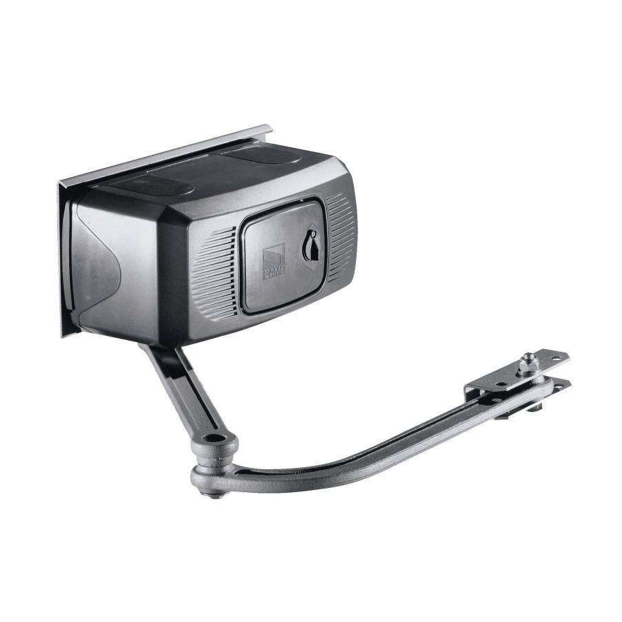
Descrizione delle parti Piastra di fi ssaggio Motoriduttore Coperchio Braccio di trasmissione snodato Accessorio opzionale: 001F1001 Braccio telescopico diritto (solo per ante da 0,5 a 2 m max.) Dimensioni Installazione L’ installazione deve essere effettuata da personale qualificato ed esperto e nel pieno rispetto delle normative vigenti. Verifiche preliminari Prima di procedere all’installazione dell’automazione è... -
Page 5: Impianto Tipo
Attrezzi e materiali Assicurarsi di avere tutti gli strumenti ed il materiale necessario, per effettuare l’installazione nella massima sicurezza, secondo le normative vigenti. Di seguito in figura l’attrezzatura minima per l’installatore. Tipologia cavi e spessori minimi Tipo Lunghezza cavo Lunghezza cavo Lunghezza cavo Collegamento cavo... - Page 6 Montaggio - Fissare la piastra di fi ssaggio al pilastro con viti e tasselli rispettando la quota minima di 150 mm dalla pavimentazione. - Fissare la staff a A (con viti o saldatura) all’anta del cancello rispettando le quote di 450 e 19 mm. Pilastro Staffa A ø...
- Page 7 - Inserire il perno quadro del braccio dritto nell’albero cavo del motore: fi ssarlo con la vite e la rondella e i 2 grani dell’albero cavo. - Aggiungere e fi ssare il braccio curvo con vite e rondella. - Sbloccare il motore (vedi paragrafo) e agganciare il braccio alla staff a A, fi ssandolo con il bullone; verifi care la libera rotazione degli snodi con alcune manovre.
- Page 8 Regolazione microinterruttori di stop in apertura e in chiusura In apertura: sbloccare e portare l’anta nella posizione di apertura desiderata. Ruotare la camma superiore fi no a far inserire il microinter- ruttore e avvitare la vite posta nella relativa camma. In chiusura (solo F 1000): sbloccare e portare l’anta nella posizione di chiusura desiderata.
- Page 9 Collegamento a quadro comando ZA3N/ZF1N/ZM3E Morsettiera quadro comando Morsettiera motore Massa Nel caso si utilizzi un solo motore (cancello a una sola anta), collegarlo su W X Y (M2) indipendentemente dal lato di montaggio. INSTALLAZIONE E COLLEGAMENTI PER APERTURA VERSO L’ESTERNO Di seguito, le uniche operazioni che variano rispetto all’installazione standard.
-
Page 10: Manutenzione
Collegamenti elettrici Per le operazioni di collegamento elettrico, utilizzare il pozzetto e le scatole di derivazione. Per ulteriori indicazioni riguardanti funzioni e regolazioni, consultare la documentazione tecnica del quadro comando. Morsettiera quadro comando Morsettiera motore Massa Nel caso si utilizzi un solo motore (cancello a una sola anta), collegarlo su W X Y (M2) indipendentemente dal lato di montaggio. Manutenzione Manutenzione periodica Prima di qualsiasi operazione di manutenzione, togliere la tensione, per evitare possibili situazioni di pericolo causate da accidentali movimen-... - Page 11 Manutenzione straordinaria La seguente tabella serve per registrare gli interventi di manutenzione straordinaria, di riparazione e di miglioramento eseguiti da ditte ⚠ esterne specializzate. Gli interventi di manutenzione straordinaria devono essere effettuati da tecnici specializzati. Registro manutenzione straordinaria Timbro installatore Nome operatore Data intervento Firma tecnico...
-
Page 12: Riferimenti Normativi
UNI EN ISO 14001 a garanzia del rispetto e della tutela dell’ambiente. Vi chiediamo di continuare l’opera di tutela dell’ambiente, che CAME considera uno dei fondamenti di sviluppo delle proprie strategie operative e di mercato, semplicemente osservando brevi indicazioni in materia di smaltimento: SMALTIMENTO DELL’IMBALLO... - Page 13 Operator FA01175-EN for swing gates F1000-F1100 INSTALLATION MANUAL EN English...
-
Page 14: Read Carefully
WARNING! important safety instructions for people: READ CAREFULLY! • REMISE PREVENT POTENTIALLY HAZARDOUS SITUATIONS EAD THE INSTRUCTIONS IF THE POWER • E MPLOY THIS PRODUCT ONLY FOR THE USE FOR WHICH IT WAS EXPRESSLY MADE SUPPLY CABLE IS DAMAGED IT MUST BE REPLACED BY THE MANUFACTURER OR AUTHORIZED .A. -
Page 15: Legend Of Symbols
Description Gearmotor This product is engineered and manufactured by CAME S.p.A. and complies with current safety regulations. The gearmotor is composed of two, cast aluminium half shells inside of which rest the gearmotor and endstops – with electro blo- cking – and an endless screw, epicycloidal gear reduction system. -
Page 16: Installation
Description of parts 1) Base plate 2) Gearmotor assembly 3) Motor cover 4) Articulated transmission arm Optional accessory : F1001 Straight telescopic arm (for single gate wings that are 0,5 to 2 m max long). Overall dimensions Installation Installation must be carried out by expert qualified personnel and in full compliance with current regulations. Preliminary checks Before installing, do the following: •... -
Page 17: Tools And Materials
Tools and materials Make sure you have all the tools and materials you will need for the installation at hand to work in total safety and compliance with the current standards and regulations. The following figure illustrates the minimum equipment needed by the installer. Cable list and minimum thickness Connection Type of cable Cable length 1 <... - Page 18 Mounting - Secure the base plate to the pillar using ø8 screws and ø14 moulded inserts making sure the minimum distance of 150mm from the ground is met. - Secure the A bracket (using ø8 screws or by welding) to the gate leaf making sure the 450mm and 19mm distances measurements and are met.
- Page 19 - Insert the straight semi-arm into the motor shaft. Apply the fl ared washer, the M6x20 screw and lock the semi-arm using the two grub screws. Join and secure the two arms using the washer and M8x16 screw. Release the motor (see p. 7) and secure the curved semi-arm to the “A”...
- Page 20 Adjusting the closing and opening-speed brake microswitches During opening: release and move the door to the open position desired. Turn the upper cam until the microswitch is activated and screw the microswitch is activated and screw the screw in the related cam. During closure (F 1000 only): release the door and move it to the desired closing position.
- Page 21 Connecting to the ZA3N/ZF1N/ZM3E control panel Control panel terminal board Motor terminals Ground If only using one motor, such as with one-leaf gates, connect it to W X Y (M2) regardless of which side it is installed on. INSTALLING AND CONNECTIONS FOR OUTWARD-OPENINGS Below are the only procedures that vary compared to standard installations: Securing the brackets N.B.
-
Page 22: Maintenance
Electrical connections For electrical connection operations, use the chamber and the junction boxes. For further information regarding functions and adjustment, refer to the technical documentation for the control panel. Control panel terminal board Motor terminals Ground If only using one motor, such as with one-leaf gates, connect it to W X Y (M2) regardless of which side it is installed on. Maintenance Periodic maintenance Before doing any maintenance, cut off the power supply, to prevent any hazardous situations caused by accidentally activating the operator. -
Page 23: Troubleshooting
Extraordinary maintenance The following table is for logging any extraordinary maintenance jobs, repairs and improvements performed by specialized contractors. ⚠ Any extraordinary maintenance jobs must be done only by specialized technicians. Extraordinary maintenance log Installer's stamp Name of operator Job performed on (date) Technician's signature Requester's signature... -
Page 24: Demolition And Disposal
CAME S.p.A. employs a UNI EN ISO 14001 certified and compliant environmental protection system at its plants, to ensure that environmental safeguarding. We ask you to keep protecting the environment, as CAME deems it to be one of the fundamental points of its market operations strategies, by simply following these brief guidelines when disposing: DISPOSING THE PACKING MATERIALS The packing components (cardboard, plastic, etc.) are solid urban waste and may be disposed of without any particular difficulty, by... -
Page 25: Manuel D' Installation
Automatisme FA01175-FR pour portails battants F1000-F1100 MANUEL D’ INSTALLATION FR Français... - Page 26 OUTE AUTRE UTILISATION EST À CONSIDÉRER COMME DANGEREUSE PHOTOCELLULES Y PASSER DEVANT UN OBJET DURANT LA FERMETURE SI L AUTOMATISME .A. D A SOCIÉTÉ CAME ÉCLINE TOUTE RESPONSABILITÉ EN CAS D ÉVENTUELS DOMMAGES INVERSE LE SENS DE LA MARCHE OU QU IL SE BLOQUE LES PHOTOCELLULES FONCTIONNENT •...
-
Page 27: Légende Des Symboles
4.00 Il convient toujours d’appliquer une serrure de verrouillage électrique sur les portails battants afin d’assurer une fermeture fiable. La société Came recommande l’installation de cette serrure en présence d’automatismes réversibles afin de garantir la sécurité anti-intrusion. En présence d’automatismes irréversibles, cette installation est obligatoire sur des vantaux de plus de 2,5 m. -
Page 28: Description Des Parties
Description des parties 1) Plaque-base 2) Groupe motoréducteur 3) Couvercle moteur 4) Bras de transmission articulé Accessoire en option: F1001 Bras télescopique droit (pour un vantail de 0,5 m à 2 m max) Mesure d’encombrement Installation Le montage doit être effectué par du personnel qualifié et expérimenté et dans le respect des normes en vigueur. Contrôles préliminaires Avant de procéder au montage, il est nécessaire de: •... -
Page 29: Outils Et Matériel
Outils et matériel Assurez-vous d’avoir tous les outils et le matériel nécessaire pour effectuer le montage de l’automatisme en toute sécurité et conformé- ment aux normes en vigueur. Sur la planche, quelques exemples de matériel pour l’installateur. Types de câbles et épaisseurs minimales Raccordement Type de câble Longueur câble 1 <... -
Page 30: Montage
Montage - Fixez la plaque-base sur le pilier avec des vis ø8 et des chevilles ø 14 en respectant la cote minimale de 150 mm. du sol. - Fixez l’étrier “A” à la porte du portail (avecvis ø8 ou soudure) en respectant les cotes de 450 et 19 mm. Pilier Étrier “A”... - Page 31 - Insérez le demi-bras droit dans l’arbre carré du moteur. Appliquez la rondelle évasée, la vis M6x20 et bloquez le demi-bras avec les deux grains. Unissez et fi xez les deux bras avec la rondelle et la vis M8x16. Débloquez le moteur (voir page 7) et fi xez le demi-bras courbé...
- Page 32 Réglage des micro-interrupteurs de ralentissement en ouverture et en fermeture En ouverture: débloquer la porte et la mettre dans la position d’ouverture voulue. Tourner la came supérieure jusqu’à ce que le microcontact s’enclenche et visser la vis qui se trouve dans la came correspondante.
- Page 33 Connexion armoire de commande ZA3N/ZF1N/ZM3E Bornier armoire de commande Bornier moteur Masse En cas d'utilisation d'un seul moteur (portail à un vantail), le connecter à W X Y (M2) indépendamment du côté de montage. INSTALLATION ET CONNEXIONS POUR UNE OUVERTURE VERS L’EXTÉRIEUR Les opérations décrites ci-après sont les seules qui varient par rapport à...
- Page 34 Branchements électriques Pour les opérations de branchement électrique, utiliser les boîtiers de dérivation. Pour toute autre indication sur les fonctions et les réglages, consulter la documentation technique de l'armoire de commande. Bornier armoire de commande Bornier moteur Masse En cas d'utilisation d'un seul moteur (portail à un vantail), le connecter à W X Y (M2) indépendamment du côté de montage. Maintenance Entretien périodique Avant toute autre opération d'entretien, il est conseillé...
- Page 35 Entretien curatif Le tableau suivant permet d'enregistrer les interventions d'entretien curatif, de réparation et d'amélioration effectuées par des sociétés ⚠ externes spécialisées. Les interventions d'entretien curatif doivent être effectuées par des techniciens qualifiés. Registre entretien curatif Timbre installateur Nom opérateur Date intervention Signature technicien Signature client...
-
Page 36: Références Normatives
Démolition et élimination CAME S.p.A. dispose au sein de son établissement d’un Système de Gestion de l’Environnement certifié et conforme à la norme UNI EN ISO 14001 pour garantir le respect et la sauvegarde de l’environnement. L’usager est prié de continuer cet effort de sauvegarde de l’environnement que Came considère comme un des facteurs de développement de ses stratégies de fabrication et commerciales, en suivant ces brèves indications concernant le recyclage:... -
Page 37: Руководство По Установке
Привод для распашных FA01175-RU ворот F1000-F1100 РУКОВОДСТВО ПО УСТАНОВКЕ RU Pусский... - Page 38 ВНИМАНИЕ! Важные правила техники безопасности: ПРОЧИТАЙТЕ ВНИМАТЕЛЬНО! П РЕДИСЛОВИЕ ФУНКЦИОНАЛЬНУЮ ПРОВЕРКУ РАБОТЫ ФОТОЭЛЕМЕНТОВ И ЧУВСТВИТЕЛЬНЫХ ПРОФИЛЕЙ • Д . Ч АННОЕ ИЗДЕЛИЕ ДОЛЖНО ИСПОЛЬЗОВАТЬСЯ ИСКЛЮЧИТЕЛЬНО ПО НАЗНАЧЕНИЮ КАЖДЫЕ ШЕСТЬ МЕСЯЦЕВ ТОБЫ ПРОВЕРИТЬ ИСПРАВНОСТЬ ФОТОЭЛЕМЕНТОВ ПРОВЕДИТЕ Л .A. С . Е ЮБОЕ...
-
Page 39: Условные Обозначения
2,5 м. Описание Привод Это изделие разработано и изготовлено компанией CAME Cancelli Automatici S.p.A в полном соответствии с действующи- ми нормами безопасности. Ассортимент представлен следующими моделями: 001F1000 - Самоблокирующийся привод в комплекте с шарнирным рычагом для створок шириной до 4 м. -
Page 40: Основные Компоненты
Основные компоненты Монтажное основание Привод Крышка Шарнирный рычаг передачи Опция: 001F1001 Прямой телескопический рычаг (только для створок от 0,5 до 2 м) Габаритные размеры (мм) Монтаж Монтаж должен производиться квалифицированным персоналом в полном соответствии с требованиями действующих норм безопасности. Предварительные проверки Перед... - Page 41 Инструменты и материалы Перед началом монтажных работ следует убедиться в наличии всех необходимых инструментов и материалов, которые позволят произвести установку оборудования в полном соответствии с действующими нормами безопасности. Ниже пред- ставлен минимальный набор инструментов для монтажника. Тип и сечение кабелей Модель...
- Page 42 Монтаж - Прикрепите монтажное основание к столбу посредством винтов и дюбелей, соблюдая минимальное расстояние от земли 150 мм. - Прикрепите скобу A (с помощью винтов или приварив) к створке ворот, соблюдая расстояния в 450 мм и 19 мм. Столб Скоба А ø...
- Page 43 Вставьте штифт квадратного сечения прямого рычага в полый вал привода и зафиксируйте с помощью болта, шайбы и двух установочных винтов полого вала. - Установите и зафиксируйте изогнутый рычаг с помощью винта и шайбы. - Разблокируйте привод (см. соответствующий пункт) и прикрепите изогнутый рычаг к скобе A с помощью прилагаемых кре- пежных...
- Page 44 5.7 Регулировка концевых микровыключателей открывания и закрывания При открывании: разблокируйте редуктор и установите створку ворот в полностью открытое положение. Поворачивайте верхний кулачок до тех пор, пока не произойдет контакт с микровыключателем, и затяните винт на соответствующем кулачке. При закрывании (только для F 1000): разблокируйте редуктор и закройте створку. Поворачивайте нижний кулачок до тех пор, пока...
- Page 45 Подключение к блоку управления ZA3N/ZF1N/ZM3E Колодка подключения блока управления Колодка подключения привода Масса Если используется только один привод (ворота с одной створкой), подключите его к W X Y (M2), вне зависимости от стороны монтажа. МОНТАЖ ПРИВОДА С ОТКРЫВАНИЕМ НАРУЖУ Ниже...
-
Page 46: Техническое Обслуживание
Электрические подключения Для подключения к электросети используйте разветвительные коробки и колодец. Чтобы получить более подробную информацию о настройках и регулировках системы, ознакомьтесь с технической документацией, прилагаемой к блоку управления. Колодка подключения блока управления Колодка подключения привода Масса Если используется только один привод (ворота с одной створкой), подключите его к W X Y (M2), вне зависимости от стороны монтажа. Техническое... -
Page 47: Возможные Неисправности И Способы Их Устранения
Внеплановое техническое обслуживание и ремонт Эта таблица необходима для записи внеплановых работ по обслуживанию и ремонту оборудования, выполненных специали- ⚠ зированными предприятиями. Ремонт оборудования должен осуществляться квалифицированными специалистами. Бланк регистрации работ по внеплановому техническому обслуживанию Место печати Компания Дата проведения работ Подпись... - Page 48 Утилизация CAME S.p.A. имеет сертификат системы защиты окружающей среды UNI EN ISO 14001, гарантирующий экологическую безопасность на ее заводах. Мы просим, чтобы вы продолжали защищать окружающую среду. САМЕ считает одним из фундаментальных пунктов стратегии рыночных отношений выполнение этих кратких руководящих принципов: УТИЛИЗАЦИЯ...
Need help?
Do you have a question about the F1000 and is the answer not in the manual?
Questions and answers