CAME F1000 Installation Manual
Automation for swing gates
Hide thumbs
Also See for F1000:
- Installation manual (49 pages) ,
- Standard installation (16 pages) ,
- Manaul (16 pages)

Related Manuals for CAME F1000


Summary of Contents for CAME F1000
- Page 1 AUTOMAZIONE 11 9 D 69 PER CANCELLI A BATTENTE Italiano Italiano English English Français Français RU IT Русский MANUALE D’INSTALLAZIONE F1000 - F1100...
-
Page 2: Leggere Attentamente
• Il prodotto deve essere destinato solo all’uso per il quale è stato alimentazione è danneggiato, esso deve essere sostituito dal costruttore o dal espressamente studiato. Ogni altro uso è da considerarsi pericoloso. CAME suo servizio di assistenza tecnica o comunque da una persona con qualifi ca Cancelli Automatici S.p.A non è... -
Page 3: Legenda Simboli
2,5 m, è obbligatoria. 3 Riferimenti normativi CAME Cancelli Automatici S.p.A. è una azienda certificata per il sistema di gestione della qualità aziendale ISO 9001 e di gestione ambientale ISO 14001. Il prodotto in oggetto è conforme alle seguenti normative: vedi dichiarazione di conformità. -
Page 4: Descrizione Delle Parti
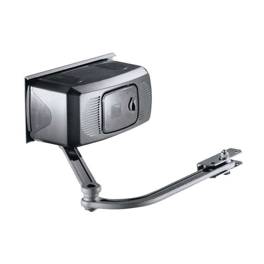
4.3 Descrizione delle parti Piastra di fi ssaggio Motoriduttore Coperchio Braccio di trasmissione snodato Accessorio opzionale: 001F1001 Braccio telescopico diritto (solo per ante da 0,5 a 2 m max.) 4.4 Dimensioni 5 Installazione L’ installazione deve essere effettuata da personale qualificato ed esperto e nel pieno rispetto delle normative vigenti. 5.1 Verifiche preliminari Prima di procedere all’installazione dell’automazione è... -
Page 5: Impianto Tipo
5.2 Attrezzi e materiali Assicurarsi di avere tutti gli strumenti ed il materiale necessario, per effettuare l’installazione nella massima sicurezza, secondo le normative vigenti. Di seguito in figura l’attrezzatura minima per l’installatore. 5.3 Tipologia cavi e spessori minimi Tipo Lunghezza cavo Lunghezza cavo Lunghezza cavo Collegamento... - Page 6 5.5 Montaggio - Fissare la piastra di fi ssaggio al pilastro con viti e tasselli rispettando la quota minima di 150 mm dalla pavimentazione. - Fissare la staff a A (con viti o saldatura) all’anta del cancello rispettando le quote di 450 e 19 mm. Pilastro Staffa A ø...
- Page 7 - Inserire il perno quadro del braccio dritto nell’albero cavo del motore: fi ssarlo con la vite e la rondella e i 2 grani dell’albero cavo. - Aggiungere e fi ssare il braccio curvo con vite e rondella. - Sbloccare il motore (vedi paragrafo) e agganciare il braccio alla staff a A, fi ssandolo con il bullone; verifi care la libera rotazione degli snodi con alcune manovre.
- Page 8 5.7 Regolazione microinterruttori di stop in apertura e in chiusura In apertura: sbloccare e portare l’anta nella posizione di apertura desiderata. Ruotare la camma superiore fi no a far inserire il microinter- ruttore e avvitare la vite posta nella relativa camma. In chiusura (solo F 1000): sbloccare e portare l’anta nella posizione di chiusura desiderata.
- Page 9 5.9 Collegamento a quadro comando ZA3N/ZF1N/ZM3E Morsettiera motore Morsettiera quadro comando Massa...
-
Page 10: Manutenzione
7 Manutenzione Manutenzione periodica Prima di qualsiasi operazione di manutenzione, togliere la tensione, per evitare possibili situazioni di pericolo causate da accidentali movimen- ☞ tazioni del dispositivo. Registro manutenzione periodica a cura dell’utente (semestrale) Data Annotazioni Firma Manutenzione straordinaria La seguente tabella serve per registrare gli interventi di manutenzione straordinaria, di riparazione e di miglioramento eseguiti da ditte ⚠ ... -
Page 11: Smaltimento Del Prodotto
UNI EN ISO 14001 a garanzia del rispetto e della tutela dell’ambiente. Vi chiediamo di continuare l’opera di tutela dell’ambiente, che CAME considera uno dei fondamenti di sviluppo delle proprie strategie operative e di mercato, semplicemente osservando brevi indicazioni in materia di smaltimento: SMALTIMENTO DELL’IMBALLO... - Page 12 HR • Za sve dodatne informacije o poduzeću, proizvodima i tehničkoj podršci: UK • Для отримання будь-якої іншої інформації про компанію, продукцію та технічну підтримку: www. came.com www. came.com CAME Cancelli Automatici S.p.a. CAME Cancelli Automatici S.p.a. Via Martiri Della Libertà, 15 31030 Dosson Di Casier...
- Page 13 AUTOMATION 11 9D 69E N FOR SWING GATES INSTALLATION MANUAL F1000 - F1100 English...
-
Page 14: Read Carefully
• Employ this product only for the use for which it was expressly made. Any the periodic maintenance log. other use is dangerous. CAME Cancelli Automatici S.p.A is not liable for any damage caused by improper, wrongful and unreasonable use • Keep these... -
Page 15: Legend Of Symbols
4.00 3 Reference Standards The company: CAME cancelli automatici is ISO 9001 quality certified; is has also obtained the ISO 14001 environmental safeguar- ding certification. CAME engineers and manufactures all of its products in Italy. This product complies with the following standards: see declaration of compliance. -
Page 16: Installation
4.3 Description of parts 1) Base plate 2) Gearmotor assembly 3) Motor cover 4) Articulated transmission arm Optional accessory : F1001 Straight telescopic arm (for single gate wings that are 0,5 to 2 m max long). 4.4 Overall dimensions 5 Installation Installation must be carried out by expert qualified personnel and in full compliance with current regulations. -
Page 17: Standard Installation
5.2 Tools and materials Make sure you have all the tools and materials you will need for the installation at hand to work in total safety and compliance with the current standards and regulations. The following figure illustrates the minimum equipment needed by the installer. 5.3 Cable list and minimum thickness Connection Type of cable Cable length 1 <... - Page 18 5.5 Mounting - Secure the base plate to the pillar using ø8 screws and ø14 moulded inserts making sure the minimum distance of 150mm from the ground is met. - Secure the A bracket (using ø8 screws or by welding) to the gate leaf making sure the 450mm and 19mm distances measurements and are met.
- Page 19 - Insert the straight semi-arm into the motor shaft. Apply the fl ared washer, the M6x20 screw and lock the semi-arm using the two grub screws. Join and secure the two arms using the washer and M8x16 screw. Release the motor (see p. 7) and secure the curved semi-arm to the “A”...
- Page 20 5.7 Adjusting the closing and opening-speed brake microswitches During opening: release and move the door to the open position desired. Turn the upper cam until the microswitch is activated and screw the microswitch is activated and screw the screw in the related cam. During closure (F 1000 only): release the door and move it to the desired closing position.
- Page 21 5.9 Connecting to the ZA3N/ZF1N/ZM3E control panel Motor terminals Control panel terminal board Ground...
-
Page 22: Maintenance
7 Maintenance Periodic maintenance Before doing any maintenance, cut off the power supply, to prevent any hazardous situations caused by accidentally activating the operator. ☞ Periodic maintenance log kept by users (every six months) Date Notes Signature Extraordinary maintenance The following table is for logging any extraordinary maintenance jobs, repairs and improvements performed by specialized contractors. ⚠ ... -
Page 23: Demolition And Disposal
CAME CANCELLI AUTOMATICI S.p.A. employs a UNI EN ISO 14001 certified and compliant environmental protection system at its plants, to ensure that environmental safeguarding. We ask you to keep protecting the environment, as CAME deems it to be one of the fundamental points of its market operations strategies, by simply following these brief guidelines when disposing: DISPOSING THE PACKING MATERIALS The packing components (cardboard, plastic, etc.) are solid urban waste and may be disposed of without any particular difficulty, by... - Page 24 HU • A vállalatra, termékeire és a műszaki szervizre vonatkozó minden további információért az Ön nyelvén: HR • Za sve dodatne informacije o poduzeću, proizvodima i tehničkoj podršci: UK • Для отримання будь-якої іншої інформації про компанію, продукцію та технічну підтримку: CAME UNITED KINGDOM LTD UNIT 3, ORCHARD BUSINESS PARK TOWN STREET, SANDIACRE NOTTINGHAM - NG10 5BP - U.K.
- Page 25 AUTOMATISME 11 9D 69FR POUR PORTAILS BATTANTS MANUEL POUR L’INSTALLATION F1000 - F1100 Français...
- Page 26 Toute autre utilisation est à considérer comme de solvants ni d'autres produits chimiques qui pourraient endommager les dangereuse. La société CAME Cancelli Automatici S.p.A. décline toute dispositifs) • En cas de réparations ou de modifi cations nécessaires des responsabilité...
-
Page 27: Légende Des Symboles
4.00 3 Normes de référence CAME cancelli automatici est une entreprise certifiée par le Système de Contrôle Qualité des Entreprises ISO 9001 et de Gestion de l’Environnement ISO 14001. Les produits CAME sont entièrement conçus et fabriqués en Italie. Le produit en objet est conforme aux normes suivantes : voir déclaration de conformité. -
Page 28: Description Des Parties
4.3 Description des parties 1) Plaque-base 2) Groupe motoréducteur 3) Couvercle moteur 4) Bras de transmission articulé Accessoire en option: F1001 Bras télescopique droit (pour un vantail de 0,5 m à 2 m max) 4.4 Mesure d’encombrement 5 Installation Le montage doit être effectué par du personnel qualifié et expérimenté et dans le respect des normes en vigueur. 5.1 Contrôles préliminaires Avant de procéder au montage, il est nécessaire de: •... -
Page 29: Installation Type
5.2 Outils et matériel Assurez-vous d’avoir tous les outils et le matériel nécessaire pour effectuer le montage de l’automatisme en toute sécurité et conformé- ment aux normes en vigueur. Sur la planche, quelques exemples de matériel pour l’installateur. 5.3 Types de câbles et épaisseurs minimales Raccordement Type de câble Longueur câble 1 <... -
Page 30: Montage
5.5 Montage - Fixez la plaque-base sur le pilier avec des vis ø8 et des chevilles ø 14 en respectant la cote minimale de 150 mm. du sol. - Fixez l’étrier “A” à la porte du portail (avecvis ø8 ou soudure) en respectant les cotes de 450 et 19 mm. Pilier Étrier “A”... - Page 31 - Insérez le demi-bras droit dans l’arbre carré du moteur. Appliquez la rondelle évasée, la vis M6x20 et bloquez le demi-bras avec les deux grains. Unissez et fi xez les deux bras avec la rondelle et la vis M8x16. Débloquez le moteur (voir page 7) et fi xez le demi-bras courbé...
- Page 32 5.7 Réglage des micro-interrupteurs de ralentissement en ouverture et en fermeture En ouverture: débloquer la porte et la mettre dans la position d’ouverture voulue. Tourner la came supérieure jusqu’à ce que le microcontact s’enclenche et visser la vis qui se trouve dans la came correspondante.
- Page 33 5.9 Connexion armoire de commande ZA3N/ZF1N/ZM3E Bornier moteur Bornier armoire de commande Masse...
- Page 34 7 Maintenance Entretien périodique Avant toute autre opération d'entretien, il est conseillé de mettre hors tension pour éviter toute situation de danger provoquée par des dépla- ☞ cements accidentels du dispositif. Registre entretien périodique tenu par l'utilisateur (semestriel) Date Remarques Signature Entretien curatif Le tableau suivant permet d'enregistrer les interventions d'entretien curatif, de réparation et d'amélioration effectuées par des sociétés...
-
Page 35: Déclaration De Conformité
à la norme UNI EN ISO 14001 pour garantir le respect et la sauvegarde de l’environnement. L’usager est prié de continuer cet effort de sauvegarde de l’environnement que Came considère comme un des facteurs de développement de ses stratégies de fabrication et commerciales, en suivant ces brèves indications concernant le recyclage: ÉLIMINATION DE L’EMBALLAGE... - Page 36 PARIS - FRANCE Tel - 0033 1 46130505 Fax - 0033 1 46130500 www. came.com www. came.com CAME Cancelli Automatici S.p.a. CAME Cancelli Automatici S.p.a. Via Martiri Della Libertà, 15 31030 Dosson Di Casier Dosson Di Casier (Tv) (+39) 0422 4940...
-
Page 37: Инструкция По Монтажу
АВТОМАТИКА 119 D 69RU ДЛЯ РАСПАШНЫХ ВОРОТ ИНСТРУКЦИЯ ПО МОНТАЖУ F1000 - F1100 Русский... - Page 38 • Данное изделие должно использоваться исключительно по назначению. подключениях. Следите за чистотой и смазкой механизмов движения Любое другое применение рассматривается как опасное. CAME Cancelli (петель) и скольжения (направляющих) • Выполняйте функциональную Automatici S.p.A. снимает с себя всякую ответственность за возможный...
-
Page 39: Условные Обозначения
Изделие соответствует требованиям следующих стандартов: смотрите декларацию о соответствии. 4. Описание 4.1 Привод Это изделие разработано и изготовлено компанией CAME Cancelli Automatici S.p.A в полном соответствии с действующи- ми нормами безопасности. Ассортимент представлен следующими моделями: 001F1000 - Самоблокирующийся привод в комплекте с шарнирным рычагом для створок шириной до 4 м. -
Page 40: Основные Компоненты
4.3 Основные компоненты Монтажное основание Привод Крышка Шарнирный рычаг передачи Опция: 001F1001 Прямой телескопический рычаг (только для створок от 0,5 до 2 м) 4.4 Габаритные размеры (мм) 5. Монтаж Монтаж должен производиться квалифицированным персоналом в полном соответствии с требованиями действующих норм безопасности. 5.1 Предварительные... - Page 41 5.2 Инструменты и материалы Перед началом монтажных работ следует убедиться в наличии всех необходимых инструментов и материалов, которые позволят произвести установку оборудования в полном соответствии с действующими нормами безопасности. Ниже пред- ставлен минимальный набор инструментов для монтажника. 5.3 Тип и сечение кабелей Модель...
- Page 42 5.5 Монтаж - Прикрепите монтажное основание к столбу посредством винтов и дюбелей, соблюдая минимальное расстояние от земли 150 мм. - Прикрепите скобу A (с помощью винтов или приварив) к створке ворот, соблюдая расстояния в 450 мм и 19 мм. Столб Скоба...
- Page 43 Вставьте штифт квадратного сечения прямого рычага в полый вал привода и зафиксируйте с помощью болта, шайбы и двух установочных винтов полого вала. - Установите и зафиксируйте изогнутый рычаг с помощью винта и шайбы. - Разблокируйте привод (см. соответствующий пункт) и прикрепите изогнутый рычаг к скобе A с помощью прилагаемых кре- пежных...
- Page 44 5.7 Регулировка концевых микровыключателей открывания и закрывания При открывании: разблокируйте редуктор и установите створку ворот в полностью открытое положение. Поворачивайте верхний кулачок до тех пор, пока не произойдет контакт с микровыключателем, и затяните винт на соответствующем кулачке. При закрывании (только для F 1000): разблокируйте редуктор и закройте створку. Поворачивайте нижний кулачок до тех пор, пока...
- Page 45 5.9 Подключение к блоку управления ZA3N/ZF1N/ZM3E Колодка подключения привода Колодка подключения блока управления Масса...
-
Page 46: Техническое Обслуживание
7. Техническое обслуживание Периодическое техническое обслуживание Перед выполнением работ по техническому обслуживанию отключите питание во избежание возникновения опасных ситуаций, ☞ вызванных непроизвольным движением устройства. Журнал периодического технического обслуживания, заполняемый пользователем (каждые 6 месяцев) Дата Выполненные работы Подпись Внеплановое техническое обслуживание и ремонт Эта... -
Page 47: Утилизация Упаковки
• Обратитесь к установщику. нальная лампа. 8. Утилизация CAME CANCELLI AUTOMATICI S.p.A. имеет сертификат системы защиты окружающей среды UNI EN ISO 14001, гарантирующий экологическую безопасность на ее заводах. Мы просим, чтобы вы продолжали защищать окружающую среду. САМЕ считает одним из фундаментальных пунктов... - Page 48 HR • Za sve dodatne informacije o poduzeću, proizvodima i tehničkoj podršci: UK • Для отримання будь-якої іншої інформації про компанію, продукцію та технічну підтримку: www. came.com www. came.com CAME Cancelli Automatici S.p.a. CAME Cancelli Automatici S.p.a. Via Martiri Della Libertà, 15 31030 Dosson Di Casier...
Need help?
Do you have a question about the F1000 and is the answer not in the manual?
Questions and answers