Harvia Sentiotec home.com4 BLACK Instructions For Installation And Use Manual
Sauna control unit
Hide thumbs
Also See for Sentiotec home.com4 BLACK:
- Instructions for installation and use manual (448 pages)

Related Manuals for Harvia Sentiotec home.com4 BLACK


Summary of Contents for Harvia Sentiotec home.com4 BLACK
- Page 1 Sauna control unit home.com4 INSTRUCTIONS FOR INSTALLATION AND USE English home.com4 Sauna control unit home.com4 BLACK 1-040-275 Sauna control unit home.com4 WHITE 1-040-276 Version 12/17 ID no. XM1254A...
-
Page 2: Table Of Contents
Table of Contents About this instruction manual Important information for your safety 2.1. Intended use 2.2. Safety information for the installer 2.3. Safety information for the user Product description 3.1. Scope of delivery 3.2. Optional accessories 3.3. Product features 3.4. Sauna operating modes 3.5. - Page 3 5.9. Foil sensor (optional) 5.10. Power booster (optional) 5.11. Remote start (optional) 5.12. Speaker output (optional) 5.13. DMX output (optional) 5.14. Finishing the installation Performing tests Connection diagram 7.1. Connection diagram basic module 230 V / 400 V 7.2. Connection diagram for basic module low voltage 7.3.
- Page 4 10.10. ECO mode 10.11. Weekly timer 10.12. Child safety control 10.13. All Off 10.14. User programs 10.15. Additional output 10.16. Activating standby for remote operation 10.17. Coloured light 10.18. Music 11. App 12. Cleaning and maintenance 12.1. Cleaning 12.2. Maintenance 13.
-
Page 5: About This Instruction Manual
Instructions for installation and use p. 5/64 1. About this instruction manual Read these installation and operating instructions carefully and keep them within reach of the sauna control unit. This ensures that you can refer to information about your safety and the operation at any time. These installation and operating instructions can also be found in the downloads section of our website: www.sentiotec.com/downloads. -
Page 6: Important Information For Your Safety
Instructions for installation and use p. 6/64 2. Important information for your safety The sauna control units of the home.com4 series have been pro- duced in accordance with the applicable safety rules and regula- tions. However, hazards may occur during use. Therefore adhere in the individual chapters. -
Page 7: Safety Information For The Installer
Instructions for installation and use p. 7/64 2.2. Safety information for the installer Work on the sauna control unit may only be performed when the power has been disconnected. A fully disconnecting all-pole isolating device compliant with The sauna control unit must be installed outside the sauna room at a height of approx. -
Page 8: Safety Information For The User
Instructions for installation and use p. 8/64 2.3. Safety information for the user The sauna control unit must not be used by children under 8 years old. The sauna control unit may be used by children above 8 years old, by persons with limited psychological, sensory or mental capabilities or by persons with lack of experience/knowledge only when: –... -
Page 9: Product Description
Instructions for installation and use p. 9/64 3. Product description 3.1. Scope of delivery Sauna control unit home.com4 Heater sensor with integrated overheat cut-out Sensor cables Installation material – 4 x chipboard screw 3 x 25 mm raised countersunk head 3.2. - Page 10 Instructions for installation and use p. 10/64 Overheat cut-out The overheat cut-out is installed in the housing for the heater sensor. Should the sauna heater continue heating after reaching the preferred temperature due to a defect, the overheat cut-out switches the sauna heater off at a tem- perature of approx.
-
Page 11: Sauna Operating Modes
Instructions for installation and use p. 11/64 3.4. Sauna operating modes The sauna control unit home.com4 provides two operating modes: sauna mode and combi-mode. If no vaporizer is connected, the menu item for operating the vaporizer can be hidden (see “9.1. Technician menu” on page 33). Sauna mode Dry heat is provided in sauna mode. - Page 12 Instructions for installation and use p. 12/64 Two-sensor mode with bench sensor (F2) In two-sensor operation with bench sensor, a second temperature sensor (bench sensor) is installed above the rear sauna bench. The sauna control unit displays the temperature measured by the bench sensor as the actual temperature. In two-sensor mode with bench sensor, the humidity is timed.
-
Page 13: Installation
Installation instructions, only for experts p. 13/64 4. Installation 4.1. Installing the control unit ATTENTION! Damage to the unit The sauna control unit is protected against splashing water, however direct contact with water could still damage the unit. Install the sauna control unit in a dry place at which a maximum humidity of 95% is not exceeded. - Page 14 Installation instructions, only for experts p. 14/64 Fig. 1 Position of the attachment device and the installation holes (dimensions in mm)
- Page 15 Installation instructions, only for experts p. 15/64 2. Use a screwdriver to remove housing screw C and lift off the housing cover from the underside (see Fig. 2). ATTENTION! When the housing cover is raised, the on/off switch D and the light switch D are released from the mounting.
-
Page 16: Cable Glands
Installation instructions, only for experts p. 16/64 4. Fasten the sauna control unit onto the cross-head screws using attachment device A as an aid (see Fig. 1). 5. Screw two chipboard screws (3 x 25 mm) into the lower fastening holes B (see Fig. -
Page 17: Installing The Heater Sensor F1 With Overheat Cut-Out
Installation instructions, only for experts p. 17/64 4.3. Installing the heater sensor F1 with overheat cut-out Observe the following points when installing the heater sensor: The heater sensor must be installed on the rear of the heater, above the mid- dle of the sauna heater. -
Page 18: Installing Bench Sensor F2 (Optional)
Installation instructions, only for experts p. 18/64 4.4. Installing bench sensor F2 (optional) The bench sensor must be installed on the wall of the sauna room, above the rear bench seat. A clearance of approx. 15 cm from the ceiling of the sauna room must be maintained. -
Page 19: Electrical Connection
Installation instructions, only for experts p. 19/64 5. Electrical connection ATTENTION! Damage to the unit The sauna control unit may only be used for operating and controlling 3 heat- ing circuits with a maximum heating capacity of 3.5 kW per heating circuit. The maximum vaporizer capacity totals 3.5 kW. - Page 20 Installation instructions, only for experts p. 20/64 Ground busbar Terminal strip for safety shut-off and sensor cables Terminal strip for cables for heater, vaporizer and power supply Terminal strip for lights and fan Terminal strip for DMX, loudspeakers, remote start and foil sensor Terminal strip for additional output Terminal strip for power booster...
-
Page 21: Power Supply Cable, Heater And Vaporizer
Installation instructions, only for experts p. 21/64 Observe the following points when connecting the power to the sauna control unit: Installation may only be performed by a qualified electrician or similarly Please observe that in the event of a guarantee claim, a copy of the bill from the electrician performing the work must be presented. -
Page 22: F1 Heater Sensor
Installation instructions, only for experts p. 22/64 5.4. F1 heater sensor 1. Guide the wires for the heater sensor through the cable gland 2 into the low-voltage connection area. 2. Connect the red wires for the heater sensor to the terminals labelled “STB” in terminal strip c. -
Page 23: Safety Shut-Off
Installation instructions, only for experts p. 23/64 5.7. Safety shut-off EN 60335-2-53 states that sauna control units with a remote start or preset timer function may only be used for operating and regulating a sauna heater which a suitable safety shut-off device can be installed in or above the heater. This shuts the sauna heater off if items such as a towel are placed on the sauna heater. -
Page 24: Power Booster (Optional)
Installation instructions, only for experts p. 24/64 5.10. Power booster (optional) 1. Feed the cable for the power booster through cable gland a into the con- nection area for 230 V/400 V. 2. Connect the cable for the power booster to terminal strip h in ac- cordance with the connection diagram. -
Page 25: Dmx Output (Optional)
Installation instructions, only for experts p. 25/64 5.13. DMX output (optional) 1. Guide the DMX connection cables for the heater sensor through the cable gland 7 into the low-voltage connection area. 2. Connect the DMS connection cables in accordance with the designations on terminal strip f. -
Page 26: Finishing The Installation
Installation instructions, only for experts p. 26/64 COLLAXX (HUE VALUE SATURATION, 8-bit) Start address: Channel 49 Channel light group 1: Channel light group 2: Channel light group 3: Channel light group 4: HSV (HUE SATURATION VALUE, 8-bit) Start address: Channel 62 Channel light group 1: Channel light group 2: Channel light group 3:... -
Page 27: Performing Tests
Installation instructions, only for experts p. 27/64 6. Performing tests WARNING! The following tests must be performed with the power supply switched on. There is a danger of electric shock. NEVER touch live parts. 1. Check the contact of the earth conductors on the earth conductor terminal. 2. -
Page 28: Connection Diagram
Installation instructions, only for experts p. 28/64 7. Connection diagram 7.1. Connection diagram basic module 230 V / 400 V Light Main power cable Vaporizer Heating system Recommended protective equipment for power cable: Power cable fuse: 3 x 20 A (CAT III) FI (residual current device): 30 mA... -
Page 29: Connection Diagram For Basic Module Low Voltage
Installation instructions, only for experts p. 29/64 7.2. Connection diagram for basic module low voltage Connection of heater sensor F1: White White Connection of bench sensor F2 and safety shut-off OSG: White White Connection of humidity temperature sensor FTS2: Black Brown Orange Green... -
Page 30: Connection Diagram For Expansion Module 230 V
Installation instructions, only for experts p. 30/64 7.3. Connection diagram for expansion module 230 V To earth bar Dimming to 500 W Switching to 3500 W Power booster... -
Page 31: Connection Diagram For Expansion Module Low Voltage
Installation instructions, only for experts p. 31/64 7.4. Connection diagram for expansion module low voltage Foil sensor connection DMX connection Remote start connection Loudspeaker connection... -
Page 32: Controls
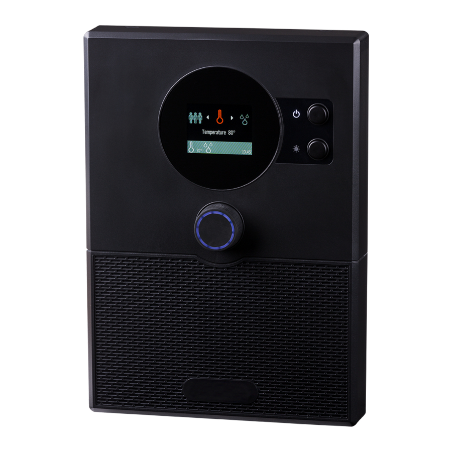
Installation instructions, only for experts p. 32/64 8. Controls Rotary selector (rotary and pushbutton for menu operation) Main switch (for switching the sauna control unit on and off) Light switch (for switching the cabin light on and off) -
Page 33: Commissioning
Installation instructions, only for experts p. 33/64 9. Commissioning 9.1. Technician menu The sauna control unit home.com4 has a technician menu separate from the main menu, in which all the basic settings can be made. The technician menu is only available in English. To access the technician menu, perform the following steps: 1. - Page 34 Installation instructions, only for experts p. 34/64 Menu item Description Setting options Language Menu language setting German, English, Swedish, French, Slovenian, Spanish, Estonian, Finnish, Italian, Dutch, Polish, Russian, Czech Time Time setting hh:mm Year Year setting Example: 2017 Month Month setting Example: July Day setting Example: 17th...
- Page 35 Installation instructions, only for experts p. 35/64 Menu item Description Setting options Colorlight Colour settings Colour proportions: Colour gradients Red: 0–100% Synchronize DMX radio transmission Green: 0–100% Blue: 0–100% Individual colour settings for the primary White: 0–100% colours red, yellow, green, turquoise, blue, violet and white - Gradient Red: On/Off...
-
Page 36: Operation
Instructions for use for the user p. 36/64 10. Operation Observe “8. Controls” on page 32. 10.1. Switching on the light (cleaning lights) The light in the sauna room can be switched on and off at the control unit inde- pendently of the On/Off switch 2. -
Page 37: Sauna Mode
Instructions for use for the user p. 37/64 10.3. Sauna mode Starting sauna mode 1. Use rotary selector 1 to select the temperature icon. Then press The “Temperature” submenu opens and the setpoint value for the temperature appears underlined in the display. 2. -
Page 38: Combi-Mode
Instructions for use for the user p. 38/64 10.4. Combi-mode Starting combi-mode 1. Use rotary selector 1 to select the temperature icon. Then press The “Humidity” submenu opens and the setpoint value for the hu- midity appears underlined in the display. 2. -
Page 39: Post-Drying Program
Instructions for use for the user p. 39/64 If the sauna control unit is used without a humidity temperature sensor (FTS2), cyclic mode is activated. If the sauna room temperature is less than 30 °C, the vaporizer is activated continuously for a preset time (10 minutes by default). -
Page 40: Cabin Light
Instructions for use for the user p. 40/64 10.6. Cabin light Switching on cabin light 1. Use rotary selector 1 switch on the cabin light. The cabin light switches on. “Light On” appears on the display. Switching off cabin light 2. -
Page 41: Preset Time
Instructions for use for the user p. 41/64 10.8. Preset time Setting the preset time You can set the preset time to the minute. The maximum preset time totals 12 hours. 1. Start the functions to be started after the preset time. 2. -
Page 42: Operating Time
Instructions for use for the user p. 42/64 10.9. Operating time In the technician menu of the sauna control unit you can now specify how long the sauna should be in continuous operation (such as 6 h for private saunas). 1 to select the runtime The “Runtime”... - Page 43 Instructions for use for the user p. 43/64 2. Press the rotary selector to change the break time. The value is now highlighted in green and can be changed. The display is in minutes. 3. There are three different break times available: 20-minute sauna break 40-minute sauna break 60-minute sauna break...
-
Page 44: Weekly Timer
Instructions for use for the user p. 44/64 10.11. Weekly timer The weekly timer allows you to automatically switch the sauna control any operating mode. Up to 14 independent On/Off operations can be programmed. Manual operation of the sauna control unit is unrestricted during this time. - Page 45 Instructions for use for the user p. 45/64 User programs [Finnish, combi, 1–5] Select the operating mode to be started. You can choose be- tween Finnish sauna (heating only), combination sauna (heating Activated [On/Off] Activate or deactivate individual On/Off operations. 2.
-
Page 46: Child Safety Control
Instructions for use for the user p. 46/64 10.12. Child safety control The sauna control unit is equipped with a child safety control which prevents children from being able to switch on the sauna heater unin- tentionally and unattended. To activate the child safety control, use rotary selector 1 to select safety control. - Page 47 Instructions for use for the user p. 47/64 The settings of the following functions are stored in the user programs: Temperature Humidity Additional output Light Coloured light Preset user programs: Light User Tempera- Humidity* program ture °C * only with active vaporizer Accessing user program: 1.
-
Page 48: Additional Output
Instructions for use for the user p. 48/64 Creating your own user programs: You can create user programs as you would like. A preset user program is overwritten in the process. Perform the following steps: 1. Start all functions that are to be switched on with the user program. 2. - Page 49 Instructions for use for the user p. 49/64 The value is now highlighted in green and can be changed. 3. Move the cursor (underscore the rotary selector. The additional output switches on. the display. Switching off additional output 4. To switch off the additional output, repeat items 1 and 3. Instead of “On”, “Off”...
-
Page 50: Activating Standby For Remote Operation
Instructions for use for the user p. 50/64 10.16. Activating standby for remote operation function must be set manually to “Standby for remote operation” mode. This activation must take place again after each remote start and stop procedure. Starting standby for remote operation: Use rotary selector 1 to select the remote start icon. -
Page 51: Coloured Light
Instructions for use for the user p. 51/64 10.17. Coloured light Starting coloured light: Use the rotary selector 1 to select the coloured light icon. Then press The “Coloured light” submenu opens and the following menu items appear on the display: Light group [1–4] operated. -
Page 52: Music
Instructions for use for the user p. 52/64 10.18. Music The music player of the sauna control unit allows you to play music in the sauna. The music is transmitted via a Bluetooth connection from a Bluetooth-enabled device (= audio source) to the sauna control unit. All Bluetooth-enabled devices, such as most mobile phones, tablets, integrated in the sauna control unit. - Page 53 Instructions for use for the user p. 53/64 If your audio source does not automatically search for Bluetooth devices in the area, start the search manually by selecting “Search for devices” or a similarly named function. 4. Choose “home.com4” from the device list displayed on the audio source.
- Page 54 Instructions for use for the user p. 54/64 Operating music via sauna control unit: Use the rotary selector 1 to open the submenu. The “Music” menu opens and in the display the control panels shown below appear: – The Artist and title display shows information about the piece of music currently being played.
-
Page 55: App
Instructions for use for the user p. 55/64 11. App All primary features of the sauna control unit “home.com4” can be operated and controlled using the Bluetooth app. To do this, download the “home.com4” app from the App Store. The app is available for iOS and Android at no charge. -
Page 56: Cleaning And Maintenance
Instructions for use for the user p. 56/64 12. Cleaning and maintenance 12.1. Cleaning ATTENTION! Damage to the unit The sauna control unit is protected against splashing water, however direct contact with water could still damage the unit. Never immerse the unit in water. Never pour water over the unit. -
Page 57: Troubleshooting
Installation instructions, only for experts p. 57/64 14. Troubleshooting 14.1. Error messages The sauna control unit is equipped with diagnostic software which monitors system statuses when it switches on and during operation. As soon as the diagnostic Errors are shown on the display as error numbers. In addition, a recurring warning tone is sounded. - Page 58 Installation instructions, only for experts p. 58/64...
- Page 59 Installation instructions, only for experts p. 59/64...
-
Page 60: Fuses
Instructions for use for the user p. 60/64 14.3. Fuses In the connection area of the sauna control unit, there are fuses for light, fan, power booster, additional output and electronics. These are time-delay micro fuses. They can be ordered using the item number PRO-FUSE. -
Page 61: Battery
Instructions for use for the user p. 61/64 14.4. Battery To keep the clock and date settings from being lost in the event of a power fail- ure, there is a battery in the basic module. This may need to be replaced if the clock no longer runs correctly. -
Page 62: Technical Data
Instructions for installation and use p. 62/64 15. Technical data Ambient conditions Storage temperature: -25 °C to +70 °C Ambient temperature: -10 °C to +40 °C Relative humidity: max. 95% Sauna control unit Dimensions (W x H x D): 210 x 294 x 53 Switched voltage / three-phase 3N: 400 V AC Frequency:... - Page 63 Instructions for installation and use p. 63/64 Thermal safety Heater sensor with overheat cut-out (139 °C shut-off temperature) Adjustable automatic heating period (6 h, 12 h, 18 h, 24 h)* Optional single-sensor mode or two-sensor mode Connection cables Power supply cable: min.
- Page 64 NOTIZEN / APPUNTI / NOTES / NOTE / NOTITIES ………………………………………………….....………………………………………………………………... ……………………………………………………………..……………………………………………………………... …………………………………………………………….....………………………………………………………... …………………………………………………….....………………………………………………………………... ……………………………………………………………..……………………………………………………………... ……………………………………………………………..……………………………………………………………... ……………………………………………………………..…………………………………………………………... …………………………………………………………….....………………………………………………………... …………………………………………………………….....………………………………………………………... …………………………………………………………….....………………………………………………………... …………………………………………………………….....………………………………………………………... …………………………………………………………….....………………………………………………………..…………………………………………………………….....………………………………………………………... …………………………………………………………….....………………………………………………………... …………………………………………………………….....………………………………………………………... …………………………………………………………….....………………………………………………………... …………………………………………………………….....………………………………………………………... …………………………………………………………….....………………………………………………………... …………………………………………………………….....………………………………………………………...
Need help?
Do you have a question about the Sentiotec home.com4 BLACK and is the answer not in the manual?
Questions and answers