Table of Contents
Advertisement
Advertisement
Table of Contents

Subscribe to Our Youtube Channel
Related Manuals for Harvia C80/1


Summary of Contents for Harvia C80/1
- Page 1 C80/1, C90, C150 Control units Steuergeräte 19022007...
-
Page 2: Table Of Contents
CoNtENts INhalt 1. CONTROL UNITS C80/1, C90 1. STEUERGERÄTE C80/1, C90 AND C150 ..........3 UND C150 ..........3 1.1. General .......... 3 1.1. Allgemeines ........3 1.2. Technical data ........ 3 1.2. Technische Daten ......3 2. INSTRUCTION FOR USE OF 2. -
Page 3: Control Units C80/1, C90
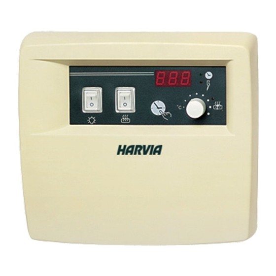
C150 UND C150 1.1. General 1.1. allgemeines Control unit C80/1 is intended for the control of Das C80/1-Steuergerät ist für die Steuerung ein- 1-phase sauna heaters (2–8 kW) in family saunas phasiger elektrischer Öfen (2–8 kW) in Familiensau- which do not have fixed control devices (1-phase nen gedacht, die keine eigebauten Regler haben electrical system). -
Page 4: Instruction For Use Of Control Unit
2. INstRUCtIoN FoR UsE oF 2. aNlEItUNG FÜR DEN BENUtZER CoNtRol UNIt DEs stEUERGERÄts Before you switch the heater on check always that Bevor Sie den Ofen anschalten, bitte überprüfen, there aren’t any things over the heater or in the dass keine Gegenstände auf dem Ofen oder in der near distance of the heater. -
Page 5: Instructions For Installing The Control Unit
Figure 2. Wall-mounting the control unit Abbildung 2. Installation des Steuergeräts an der Wand Figure 4. Fastening the device to the wall Abbildung 4. Wandbefestigung Figure 3. Location of hole blanks in the base plate of the control unit Abbildung 3. Stellen der vorbereiteten Bohrungen am unteren Rand des Steuergeräts 3. -
Page 6: Installation Of Sensor Box
Figure 5. The place of the sensor box of the control units in connection with wall-mounted heaters. Abbildung 5. Lage des Fühlergehäuses des Steuergeräts bei Saunaöfen mit Wandmontage. Figure 6. The position of the sensor box of the control unit C150 in connection with heaters attached to the floor. Abbildung 6. -
Page 7: Changing The Pre-Set Time
(C150; 2 Stk) wird die elektrische Leistung zum heater (in the C90 control unit there are a safety Ofen geleitet (im Steuergerät C90 befinden sich contactor and three power relays, in the C80/1 ein Sicherheitskontaktor und 3 Leistungsrelais, im control unit there are 2 pcs 1-phase contactors). - Page 8 Figure 9a. Electrical power card C150 Figure 9b. Electrical power card C80 Abbildung 9a. Leistungsplatte C150 Abbildung 9b. Leistungsplatte C80 the electric power card must be changed, if Die leistungsplatte muß gewechselt werden, wenn indicator light 8 shows the heater is on, but die Kontrolleuchte (8) anzeigt, daß...
- Page 9 Figure 10a. The electric power card C80 Abbildung 10a. Die Leistungsplatte C80 Figure 10b. The electric power card C90 Abbildung 10b. Die Leistungsplatte C90 Figure 10c. The electric power card C150 Abbildung 10c. Die Leistungsplatte C150...
- Page 10 JM-heaters, as well as for the control control unit C80/1 unit C80/1 Abbildung 11. Elektroanschlüsse der M-, KV-, und KIP- Abbildung 12. Elektroanschlüsse der D, und JM- Saunaöfen sowie des Steuergeräts C80/1 Saunaöfen sowie des Steuergeräts C80/1 Table 1. Tabelle 1. Type...
- Page 11 Figure 13. Electrical connections for the M-, KV-, Figure 14. Electrical connections for the KV-, D- and KIP-heaters, as well as for the and JM-heaters, as well as for the control unit C90 control unit C90 Abbildung 13. Elektroanschlüsse der M-, KV-, und KIP- Abbildung 14.
- Page 12 *) For thermostat/ Zur Thermostat: 4 x 0,25 – 4 x 0,5 mm (T170) Figure 16. Reset button for overheating limiter Installing the temperature sensor near the Abbildung 16. ventilation valves. Rücksetzknopf des Überhitzungsschutzes Montage des Temperaturfühlers in der Nähe des Lüftungsventils. Harvia Oy PL 12 40951 Muurame Finland www.harvia.fi...
Need help?
Do you have a question about the C80/1 and is the answer not in the manual?
Questions and answers