Table of Contents
Advertisement
Quick Links
HARVIA XENIO COMBI
CX30C-U1 / CX30C-U1-XW (WiFi)
CX30C-U3 / CX30C-U3-XW (WiFi)
Instructions for Installation and Use of Control Unit
Instructions d'installation et d'utilisation du centre de contrôle
ETL LISTED
Conforms to
UL 60730-1
UL 60730-2-7
UL 60730-2-9
Certified to
CSA E60730-1
CSA E60730-2-7
CSA E60730-2-9
01112021/Y05-0656
HARVIA XENIO COMBI
CX004WIFI
Advertisement
Table of Contents

Related Manuals for Harvia CX30C-U1-XW


Summary of Contents for Harvia CX30C-U1-XW
- Page 1 HARVIA XENIO COMBI CX30C-U1 / CX30C-U1-XW (WiFi) CX30C-U3 / CX30C-U3-XW (WiFi) Instructions for Installation and Use of Control Unit Instructions d'installation et d'utilisation du centre de contrôle HARVIA XENIO COMBI CX004WIFI ETL LISTED Conforms to UL 60730-1 UL 60730-2-7 UL 60730-2-9...
-
Page 2: Table Of Contents
! HARVIA XENIO CONTROL UNIT (CX30C-U1 / CENTRE DE CONTRÔLE HARVIA XENIO CX30C-U3 / CX30C-U1-XW (WiFi) / CX30C-U3- (CX30C-U1 / CX30C-U3 / CX30C-U1-XW (WiFi) / XW (WiFi)) CX30C-U3-XW (WiFi)) Control unit's purpose of use: The control unit is Fonction du centre de contrôle : le centre de... -
Page 3: Harvia Xenio
1. HARVIA XENIO 1.1. General 1.1. Généralités The Harvia Xenio control unit consists of a control Le centre de contrôle Harvia Xenio se compose d’un panel, a power unit, a temperature sensor and a panneau de commande, d’un bloc d’alimentation, humidity sensor. -
Page 4: Troubleshooting
Control panel Temperature sensor WX232 Tableau de commande Capteur de température WX232 Humidity sensor WX325 Capteur d´humidité WX325 Power unit Bloc d’alimentation Combi heater Poêle Combi Main switch Commutateur principal Figure 1. System components Figure 1. Composants de système 1.3. Troubleshooting 1.3. - Page 5 Description Remedy/Solution Temperature sensor's measuring circuit Check the red and yellow wires to the temperature sensor and their broken. connections (see Figures 6a and 6b) for faulties. Circuit de mesure du capteur de température Vérifiez si les fils rouge et jaune du capteur de température et leurs hors service.
-
Page 6: Instructions For Use
2.1.1. Poêle et/ou évaporateur allumés Heater and steamer are switched on and off inde- La poêle et l’évaporateur sont allumés et éteints pendently (only with the Harvia Xenio CX30C-U1, indépendamment. (uniquement avec le modèle Har- CX30C-U1-XW (WiFi) model). via Xenio CX30C-U1, CX30C-U1-XW (WiFi)). -
Page 7: Heater And/Or Steamer Off
When the heater and/or steamer starts, the display Lorsque la poêle et/ou l’évaporateur démarre, will show previously set values for five seconds. l’affichage présente les valeurs réglées précé- The shown values (temperature/humidity/on-time) demment pendants cinq secondes. Les valeurs differ depending on which devices are started. affichées (température/humidité/fonctionnement) When the desired temperature and/or humidity varient selon les dispositifs enclenchés. -
Page 8: Remote Switch
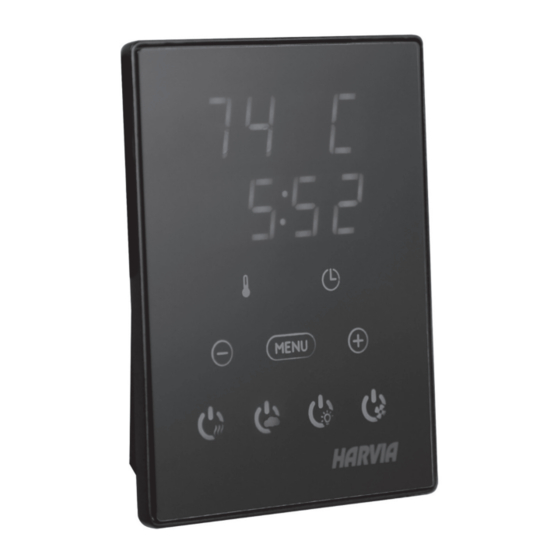
2.2.3. Safety switch 2.2.3. Commutateur de sécurité Safety switch refers to e.g. Harvia SFE, a safety Parmi les commutateurs de sécurité figurent par device installed above or integrated to the heater, exemple le Harvia SFE, un dispositif de sécurité... - Page 9 Mode basique (poêle et évaporateur allumés) Basic mode (heater and steamer on) The top row shows the sauna room La ligne supérieure montre la température du temperature. The bottom row shows the sauna. La ligne inférieure montre la valeur humidity level (or remaining on-time, if the d’humidité...
- Page 10 ADDITIONAL SETTINGS/AUTRES REGLAGES Control unit standby Veille du centre de contrôle Open the settings menu by simultaneously Ouvrez le menu de réglages en appuyant pressing the locations of the buttons –, simultanément sur les boutons –, MENU et +. MENU and +. Press for 5 seconds. Maintenez la pression pendant 5 secondes.
- Page 11 UL STD 875 B1 (default/défaut), B2, B3, B4, B5 CERTIFIED TO HL(S)11U3(Q) 10,5 kW CAN/CSA STD HARVIA OY, FINLAND *Q = includes built-in contactor / contient le contacteur integré 3159549 E60335-2-53-05 C1, C2, C3, C4, C5 D1, D2, D3, D4, D5...
-
Page 12: Instructions For Installation
3. INSTRUCTIONS FOR INSTALLATION 3. INSTRUCTIONS D’INSTALLATION The electrical connections of the control unit may Les connexions électriques du centre de contrôle peu- only be made by a licensed professional electrician vent uniquement être effectuées par un électricien pro- and in accordance with the current regulations. fessionnel agréé... -
Page 13: Installing The Control Panel
3.1. Installing the Control Panel 3.1. Installer le tableau de commande The control panel is splashproof and has a low Le panneau de commande est étanche aux écla- operating voltage. The panel can be installed in the boussures et présente une faible tension de fonc- dressing room, or in the living quarters. -
Page 14: Instructions For Installation
WX232 is needed to operate CX30C-U1/ Le modèle WX232 est nécessaire pour • • CX30C-U1-XW (WiFi) and CX30C-U3/ CX30C- l’utilisation du CX35-U1-U3 / CX35-U1- U3-XW (WiFi). See section 3.3. for correct U3-XW (WiFi) et CX45-U1-U3 / CX45-U1- temperature sensor placement. - Page 15 K A1 Figure 6a. Electrical connections 240 V, 1Ph (CX30C-U1 / CX30C-U1-XW (WiFi)) Figure 6a. Connexions électriques 240 V, 1Ph (CX30C-U1 / CX30C-U1-XW (WiFi))
- Page 16 L2 L3a K A1 Figure 6b. Electrical connections 208 V, 3Ph (CX30C-U3 / CX30C-U3-XW (WiFi)). Figure 6b. Connexions électriques 208 V, 3Ph (CX30C-U1 / CX30C-U1-XW (WiFi)).
-
Page 17: Power Unit Breaker Faults
3.2.3. Power Unit Breaker Faults 3.2.3. Défaillances du fusible du bloc Replace a blown breaker by a new one with the d’alimentation same resistance. The placement of the breakers in Un fusible grillé doit être remplacé par un fusible the power unit is shown in Figures 6a and 6b. neuf. -
Page 18: Installing The Humidity Sensor
3.4. Installing the Humidity Sensor 3.4. Installer le capteur d’humidité Fasten the humidity sensor on the wall as far from Fixez le capteur d’humidité sur le mur aussi loin the heater as possible and at a distance of 20–28’’ que possible du poêle et à une distance de 20–28’’ (500–700 mm) from the ceiling. - Page 19 A / D = Safety distance of heater 3 15/16” (Check from heater manual)/ (100 mm) Distance de sécurité du poêle (Vérifier dans le manuel du poêle) Temperature sensor Capteur de température Humidity sensor Temperature sensor Capteur d’humidité Capteur de température Permitted area for humidity sensor...
-
Page 20: Spare Parts
Capteur de température WX232 Humidity sensor Capteur d´humidité WX325 WX357 Circuit board Circuit imprimé Contactor 30 A (CX30C-U1, CX30C-U1-XW, Contacteur 30 A (CX30C-U1, CX30C-U1-XW, ZSK-778 CX30C-U3, CX30C-U3-XW) CX30C-U3, CX30C-U3-XW) MAINTENANCE INSTRUCTIONS INSTRUCTIONS D’ENTRETIEN 1. All service operations must be done by profes- 1. -
Page 21: Guarantee
15 jours suivant l’achat. La garantie s’applique uniquement à la première ins- tallation du produit et à l’acheteur d’origine. Harvia control unit model/ Modèle de centre de contrôle Harvia Model number/Numéro de modèle Date of purchase/Date d’achat Original purchaser/Acheteur d’origine Address/Adresse Purchased from/Acheté...
Need help?
Do you have a question about the CX30C-U1-XW and is the answer not in the manual?
Questions and answers