Harvia CX170-U1 Owner's/Operator's Manual
Hide thumbs
Also See for CX170-U1:
- Owner's/operator's manual (25 pages) ,
- Owner's and operator's manual (18 pages) ,
- Owner's/operator's manual (20 pages)
Table of Contents
Advertisement
Quick Links
Owner's/Operator's Manual
Manuel de l'utilisateur/opérateur
Instructions for Installation and
Use of Control Unit
IMPORTANT! This manual must
be left with owner, manager, or
operator of Sauna after it is used by
electrician!
MODEL
CX170-U1
CX170-U1-15
CX170-U3
CX170-U3-15
07052020/Y05-0653
240 V 1N~
240 V 1N~
208 V 3N~
208 V 3N~
Instructions d'installation et
d'utilisation du centre de contrôle
IMPORTANT ! Ce manuel doit être
remis au propriétaire, au gérant ou à
l'opérateur du sauna après avoir été
utilisé par l'électricien !
Advertisement
Table of Contents

Related Manuals for Harvia CX170-U1


Summary of Contents for Harvia CX170-U1
- Page 1 à operator of Sauna after it is used by l’opérateur du sauna après avoir été electrician! utilisé par l’électricien ! MODEL CX170-U1 240 V 1N~ CX170-U1-15 240 V 1N~ CX170-U3 208 V 3N~ CX170-U3-15...
-
Page 2: Table Of Contents
à la personne chargée de maintaining them. Congratulations on making an leur maintenance. Félicitations pour cet excellent excellent choice and choosing a Harvia control choix ! unit! HARVIA XENIO CONTROL UNIT (CX170-U1, CENTRE DE CONTRÔLE HARVIA XENIO... -
Page 3: Harvia Xenio
1. HARVIA XENIO 1.1. General 1.1. Généralités The Harvia Xenio control unit consists of a control Le centre de contrôle Harvia Xenio se compose d’un panel, a power unit and a sensor. See Figure 1. panneau de commande, d’un bloc d’alimentation et The control unit regulates the temperature in d’un capteur de température. -
Page 4: Troubleshooting
Sensor: Capteur : Temperature sensor NTC thermistor 22 kΩ/ Capteur de température à thermistance NTC • • T=77 ºF (25 ºC) 22 kΩ/T=77 °F (25 °C). Resettable overheat protector Sécurité de surchauffe réinitialisable • • Dimensions: 2.0” x 2.9” x 1.1” (51 mm x Dimensions : 2.0”... -
Page 5: Instructions For Use
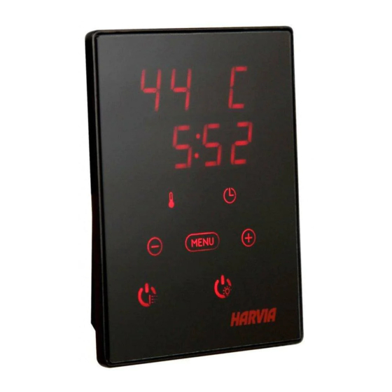
2. INSTRUCTIONS FOR USE 2. MODE D’EMPLOI 2.1. Using the Heater 2.1. Utiliser la poêle WARNING! Before switching the heater on always REMARQUE ! Avant la mise en marche de la poêle, véri- check that there isn’t anything on top of the heater fier qu’aucun objet n’est posé... - Page 6 BASIC SETTINGS/REGLAGES DE BASE Basic mode (heater on) Mode basique (poêle allumé) The top row shows the temperature in the La ligne supérieure montre la température du sauna room. The bottom row shows the sauna. La ligne inférieure montre la durée de remaining on time.
- Page 7 ADDITIONAL SETTINGS/AUTRES REGLAGES Control unit standby Veille du centre de contrôle Open the settings menu by simultaneously Ouvrez le menu de réglages en appuyant pressing the locations of the buttons –, simultanément sur les boutons –, MENU et +. MENU and +. Press for 5 seconds. Maintenez la pression pendant 5 secondes.
-
Page 8: Safety Switch
Figure 3b. Durée de fonctionnement maximale (à l’usage commercial seulement) 2.2.3. Safety switch 2.2.3. Commutateur de sécurité Safety switch refers to e.g. Harvia SFE, a safety Parmi les commutateurs de sécurité figurent par device installed above or integrated to the heater, exemple le Harvia SFE, un dispositif de sécurité... -
Page 9: Remote Switch
2.2.4 Remote switch 2.2.4. Télécommande To remotely control the heater’s power input, Pour contrôler à distance la puissance du poêle, the control unit can be equipped with an on/off le centre de contrôle peut être équipé d’une remote switch (e.g. building automation). For more télécommande de marche/arrêt (par ex. -
Page 10: Instructions For Installation
3. INSTRUCTIONS FOR INSTALLATION 3. INSTRUCTIONS D’INSTALLATION The electrical connections of the control unit Les connexions électriques du centre de contrôle peu- may only be made by an authorised, professional vent uniquement être effectuées par un électricien pro- electrician and in accordance with the current fessionnel agréé... -
Page 11: Installing The Power Unit
be at the minimum safety distance from the heater installé à la distance de sécurité minimum du poêle and at a maximum height of one metre from the et à une hauteur maximum d’un mètre par rapport floor. Figure 4. au sol. - Page 12 Instructions for Installation Instructions d’installation The power unit of CX170-U1 is controlled by control panel Xenio. Le bloc d'alimentation de la CX170-U1 est commandé par le tableau de com- Control panel is connected to power unit via data cable. mande Xenio.
- Page 13 Instructions for Installation Instructions d’installation The power unit of CX170-U1-15 is controlled by control panel Le bloc d'alimentation de la CX170-U1-15 est commandé par le tableau de Xenio. commande Xenio. Control panel is connected to power unit via data cable.
- Page 14 MODEL WATTS AMPS VOLTAGE PH WIRE SIZE/CALIBRE DE FIL AMPÈRES TENSION MODÈLE breaker to power unit power unit to heater du coupe-circuit au bloc du bloc d’alimentation au d’alimentation poêle KIP-30-W3, FIN-30-W3 3 000 #16 copper/cuivre #16 copper/cuivre KIP-45-W3, FIN-45-W3 4 500 12,5 #14 copper/cuivre #14 copper/cuivre...
- Page 15 MODEL WATTS AMPS VOLTAGE PH WIRE SIZE/CALIBRE DE FIL AMPÈRES TENSION MODÈLE breaker to power unit power unit to heater du coupe-circuit au bloc du bloc d’alimentation au d’alimentation poêle KIP-30-W3, FIN-30-W3 3 000 #16 copper/cuivre #16 copper/cuivre KIP-45-W3, FIN-45-W3 4 500 12,5 #14 copper/cuivre #14 copper/cuivre...
-
Page 16: Installing The Temperature Sensor
problème. Dans le poêle, vérifiez le contacteur de sécurité, la sécurité-surchauffe du poêle et leur câblage. 3.3. Installing the Temperature Sensor 3.3. Installer le capteur de température Floor-mounted heaters (see Figure 7) Poêles en installation au sol (figure 7) Option 1: The temperature sensor is mounted Option 1 : Fixez le capteur de température •... - Page 17 min. 3 15/16” (100 mm) Sensor max. Capteur Sensor 7 7/8” Capteur Sensor (200 mm) Capteur A min. A max. A min. A min. A max. A min. MODEL/MODÈLE Model A min. A max. D min. K10G-U1, K12,5G-U1, K15G-U1 Modèle inch (mm) inch (mm) inch (mm)
-
Page 18: Resetting The Overheat Protector
Sensor Capteur 5 7/8“ (150 mm) MODEL/MODÈLE KIP-30-W1, FIN-30, KIP-45-W1, FIN-45 KIP-60-W1, FIN-60, KIP-80-W1, FIN-80 KIP-30-W3, FIN-30-W3, KIP-45-W3, FIN-45-W3 KIP-60-W3, FIN-60-W3, KIP-80-W3, FIN-80-W3 Figure 8. The place of the temperature sensor of Figure 9. Sensor’s minimum distance from an air vent the control unit in connection with wall- Figure 9. -
Page 19: Spare Parts
Câble de rallonge 10 m (en option) WX313 Temperature sensor Capteur de température WX232 Circuit board Circuit imprimé WX361 6a Contactor 30 A (CX170-U1, CX170-U3) Contactor 30 A (CX170-U1, CX170-U3) ZSK-778 6b Contactor 45 A (CX170-U3-15, CX170-U1-15) Contactor 45 A (CX170-U3-15, CX170-U1-15) ZSL-940... -
Page 20: Guarantee
à l’importateur dans les 15 jours suivant l’achat. La garantie s’applique uniquement à la première instal- lation du produit et à l’acheteur d’origine. Harvia control unit model/Modèle de centre de contrôle Harvia Model number/Numéro de modèle Date of purchase/Date d’achat Original purchaser/Acheteur d’origine...
Need help?
Do you have a question about the CX170-U1 and is the answer not in the manual?
Questions and answers
Line side wiring is ok and the load side is ok. A1 and A2 is ok why am I blowing the 40 mili amp fuse in the control box. Need help!
@Mark butler What do you think?