Table of Contents
Advertisement
Quick Links
Advertisement
Table of Contents

Related Manuals for Badger Meter Blancett QuikSert B131-038


Summary of Contents for Badger Meter Blancett QuikSert B131-038
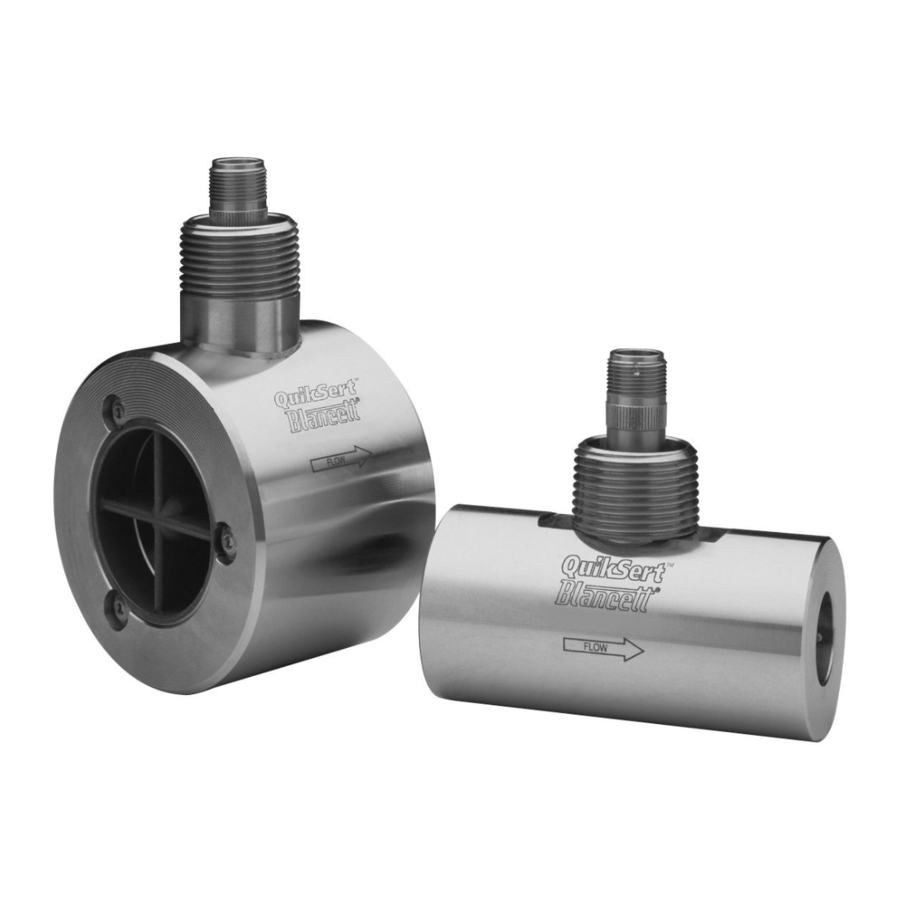
- Page 1 Turbine Flow Meter QuikSert® Standard User Manual TRB-UM-00372-EN-03 (April 2016)
-
Page 2: Table Of Contents
Turbine Flow Meter, QuikSert® Standard CONTENTS Scope of This Manual � � � � � � � � � � � � � � � � � � � � � � � � � � � � � � � � � � � � � � � � � � � � � 3 Unpacking and Inspection �... -
Page 3: Scope Of This Manual
Scope of This Manual SCOPE OF THIS MANUAL This manual is intended to help you get the QuikSert turbine flow meter up and running quickly� MPORTANT Read this manual carefully before attempting any installation or operation. Keep the manual accessible for future reference. UNPACKING AND INSPECTION Upon opening the shipping container, visually inspect the product and applicable accessories for any physical damage such as scratches, loose or broken parts, or any other... -
Page 4: Operating Principle
Operating Principle OPERATING PRINCIPLE Fluid entering the meter passes through the inlet flow straightener which reduces its turbulent flow pattern and improves the fluid’s velocity profile� Fluid then passes through the turbine, causing it to rotate at a speed proportional to the fluid velocity� As each turbine blade passes through the magnetic field, the blade generates an AC voltage pulse in the pickup coil at the base of the magnetic pickup (see Figure... - Page 5 Installation Figure 2: Meter installation using a bypass line Figure 3: Meter installation without using a bypass line 7� Install all restrictions in the flow line that may cause the liquid to flash, downstream of the meter� If necessary, install air eliminators so the meter is not incorrectly measuring entrained air or gas�...
-
Page 6: Operational Startup
Operational Startup OPERATIONAL STARTUP Follow these steps when installing and starting the meter� MAKE SURE THAT FLUID FLOW HAS BEEN SHUT OFF AND PRESSURE IN THE LINE RELEASED BEFORE ATTEMPTING TO INSTALL THE METER IN AN EXISTING SYSTEM. 1� Close the isolation valves and open the bypass valve after installing the meter� 2�... -
Page 7: Troubleshooting Guide
Troubleshooting Guide TROUBLESHOOTING GUIDE Trouble Possible Cause Remedy • Cavitation • Debris on • Increase back pressure rotor support • Clean meter Meter indicates higher than actual • Build up of foreign • Clean meter flow rate material on • Install gas eliminator meter bore ahead of meter... -
Page 8: Part Number Information
Part Number Information PART NUMBER INFORMATION Flow Ranges Part Meter Bore Size × Line Size Number m³/D B131-038 3/8 in� × 1 in� (9�5 mm × 25�4 mm) 0�6…3 20…100 3�3…16 B131-050 1/2 in� × 1 in� (12�7 mm × 25�4 mm) 0�75…7�5 25…250 4�1…41... -
Page 9: Repair Kit Information
Repair Kit Information REPAIR KIT INFORMATION Meter Part Repair Kit Part Max. Pressure Dimensions Number Number Drop diameter × length B131-038 B253-102 3�75 psi 2 in� × 4 in� (50�4 mm × 101�6 mm) B131-050 B253-105 6�5 psi 2 in� × 4 in� (50�4 mm × 101�6 mm) B131-075 B253-108 18 psi... -
Page 10: Specifications
Specifications SPECIFICATIONS Body and Internal 316 stainless steel Wetted Parts Materials of Rotor CD4MCU stainless steel Construction Bearings Tungsten carbide Rotor Shaft Tungsten carbide –150…350° F (–101…177° C) The meter should not be subjected to temperatures above Temperature 350° F (177° C), or below –150° F (–101° C) or the freezing point of the metered liquid�... - Page 11 Specifications Figure 5: Typical cross-section of models B132-050…B139-900 April 2016 TRB-UM-00372-EN-03 Page 11...
- Page 12 The Americas | Badger Meter | 4545 West Brown Deer Rd | PO Box 245036 | Milwaukee, WI 53224-9536 | 800-876-3837 | 414-355-0400 México | Badger Meter de las Americas, S.A. de C.V. | Pedro Luis Ogazón N°32 | Esq. Angelina N°24 | Colonia Guadalupe Inn | CP 01050 | México, DF | México | +52-55-5662-0882...
Need help?
Do you have a question about the Blancett QuikSert B131-038 and is the answer not in the manual?
Questions and answers