Table of Contents
Advertisement
Quick Links
Advertisement
Table of Contents

Related Manuals for Badger Meter Blancett B2900


Summary of Contents for Badger Meter Blancett B2900
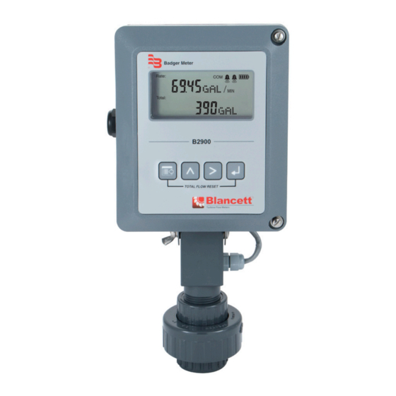
- Page 1 Digital Flow Monitor B2900 User Manual DSY-PM-01378-EN-08 (May 2020)
- Page 2 Digital Flow Monitor, B2900 Page ii DSY-PM-01378-EN-08 May 2020...
-
Page 3: Table Of Contents
User Manual CONTENTS Scope of This Manual � � � � � � � � � � � � � � � � � � � � � � � � � � � � � � � � � � � � � � � � � � � � 5 Safety �... - Page 4 Digital Flow Monitor, B2900 Troubleshooting Guide� � � � � � � � � � � � � � � � � � � � � � � � � � � � � � � � � � � � � � � � � � 39 Default K-Factor Values �...
-
Page 5: Scope Of This Manual
Scope of This Manual SCOPE OF THIS MANUAL This manual is intended to help you get the B2900 flow monitor up and running quickly� IMPORTANT Read this manual carefully before attempting any installation or operation. Keep the manual accessible for future reference. Unpacking and Inspection Upon opening the shipping container, visually inspect the product and applicable accessories for any physical damage such as scratches, loose or broken parts, or any other... -
Page 6: Electrical Symbols
Introduction IMPORTANT Not following instructions properly may impair safety of equipment and/or personnel. Electrical Symbols Direct Alternating Earth Protective Chassis Function Current Current (Ground) Ground Ground Symbol INTRODUCTION The B2900 flow monitor incorporates state-of-the-art, digital signal processing technology, designed to provide exceptional flexibility at a very affordable price� Though designed for use with Blancett flow sensors, this monitor can be used with almost any flow sensor producing a low amplitude AC output or contact closure signal�... -
Page 7: Installation
Installation INSTALLATION Connecting the B2900 Monitor to a Frequency Output Device The B2900 monitor has two jumpers for setting the type of signal and the minimum amplitude of the signal that it accepts� First, establish the type of output provided by the flow sensor�... - Page 8 Installation If the minimum signal level is below 60 mV, use the high signal sensitivity jumper position� RS485 B (–) RS485 A (+) RS485 Gnd Pulse Setpoint 1 Setpoint 2 Freq. In – Pulse 4-20mA – Iso Total Pluse – Total Reset High OC Total Pluse...
-
Page 9: Power Connections
Power Connections POWER CONNECTIONS Standard The power supply used in the B2900 monitor is an internal lithium 3�6V DC D cell that powers the monitor for about six years when no outputs are used� The monitor can also get power from a 4…20 mA current loop� See Figure 5�... -
Page 10: Operating The Monitor
Operating the Monitor OPERATING THE MONITOR Buttons Figure 6: Keypad detail Switches to Program mode, press and hold for three seconds to enter MENU Extended Programming mode, saves programming information and is used in the reset process Scrolls backward through the parameter choices, increments numeric variables and increases display contrast in Run mode Scrolls forward through the parameter choices, moves the active digit to the RIGHT... -
Page 11: Modes Of Operation
Operating the Monitor Modes of Operation The monitor has three modes of operation— Run, Programming and Extended Programming modes� Communications Alarm Indicator Activation Battery Indicator Rate Rate Units Totalizer Multiplier Total Totalizer Units Figure 7: Display annunciators Normal operating mode Program Program variables into the display Extended Program Program advanced variables into the display... -
Page 12: Menu Structure
Menu Structure MENU STRUCTURE Liquid START Rate SU RateInt Fluid (Rate Unit Setup) (Rate time interval) Liquid Simple Advanced Second Minute Hour Hour RateUnt (Rate/Total Units) Meter (Size) Gallons/Min 0.250 RateUnt Gallons 0.375 OB/D Oil Barrel/Day (Unit/interval=T) 0.500 m³/D Meters³/Day Gallons/T 0.625 m³... - Page 13 Menu Structure Liquid (continued) Continued from B on previous page. Clr G-T TotlMult 4-20Cal (Clear Grand Total) (Totalizer Multiplier) (Calibrate 4-20) ×1000 × 1000 ×100 × 100 ×10 × 10 4mA Out Passwd × 1 × 0.1 (4 mA Output) (Password) 0.01 ×...
-
Page 14: Advanced I/O Liquid
Menu Structure Advanced I/O Liquid START RateInt TotlMult Fluid (Rate time interval) (Totalizer Multiplier) Liquid Second ×1000 × 1000 Minute ×100 × 100 Hour Hour ×10 × 10 × 1 Meter (Size) × 0.1 0.01 × 0.01 0.250 RateUnt 0.375 (Unit/interval=T) 0.500 Gallons/T... - Page 15 Menu Structure Advanced I/O Liquid (continued) Continued from previous page. 4-20Cal Modbus (Calibrate 4-20) Enable Disable BusAddr 4mA Out Modbus Address (1 to127) (4 mA Output) Numeric Entry Numeric Entry SetPT1 20mA Out (Setpoint 1) Passwd Passwd (20 mA Output) Numeric Entry Password (Password)
-
Page 16: Gas
Menu Structure START RateInt TotlMult Fluid (Rate time interval) (Totalizer Multiplier) Liquid Second ×1000 × 1000 Minute ×100 × 100 Hour Hour ×10 × 10 × 1 Meter (Size) × 0.1 2.0 in. Low 0.01 × 0.01 RateUnt 2.0 in. Med (Unit/interval=T) 2.0 in. - Page 17 Menu Structure Gas (continued) Continued from previous page. Clr G-T Damping 4-20Cal (Clear Grand Total) (Display Damping) (Calibrate 4-20) Numeric Entry PulsOut 4mA Out Passwd (Pulse Output) (Password) (4 mA Output) Disable Numeric Entry Numeric Entry Enable RstPswd 20mA Out Fl=20mA (Reset Password) (20 mA Output)
-
Page 18: Advanced I/O Gas
Menu Structure Advanced I/O Gas START RateInt TotlMult Fluid (Rate time interval) (Totalizer Multiplier) Liquid Second ×1000 × 1000 Minute ×100 × 100 Hour Hour ×10 × 10 × 1 Meter (Size) × 0.1 2.0 in. Low 0.01 × 0.01 RateUnt 2.0 in. - Page 19 Menu Structure Advanced I/O Gas (continued) Continued from previous page. Damping 4-20Cal Modbus (Display Damping) (Calibrate 4-20) Numeric Entry Enable Disable PulsOut BusAddr 4mA Out (Pulse Output) Modbus Address (1 to127) (4 mA Output) Numeric Entry Disable Numeric Entry Enable SetPT1 20mA Out (Setpoint 1)
-
Page 20: Liquid (Solar Powered)
Menu Structure Liquid (Solar Powered) START Rate SU RateInt Fluid (Rate Unit Setup) (Rate time interval) Liquid Simple Advanced Second Minute Hour Hour RateUnt (Rate/Total Units) Meter (Size) Gallons/Min 0.250 RateUnt Gallons 0.375 OB/D Oil Barrel/Day (Unit/interval=T) 0.500 m³/D Meters³/Day Gallons/T 0.625 m³... - Page 21 Menu Structure Liquid (Solar Powered) (continued) Continued from B on previous page. PulsOut Clr G-T TotlMult (Pulse Output) (Clear Grand Total) (Totalizer Multiplier) ×1000 × 1000 Disable ×100 × 100 Enable ×10 × 10 Passwd × 1 Linear × 0.1 (Password) (Linearization) 0.01...
-
Page 22: Gas (Solar Powered)
Menu Structure Gas (Solar Powered) START RateInt TotlMult Fluid (Rate time interval) (Totalizer Multiplier) Liquid Second ×1000 × 1000 Minute ×100 × 100 Hour Hour ×10 × 10 × 1 Meter (Size) × 0.1 2.0 in. Low 0.01 × 0.01 RateUnt 2.0 in. - Page 23 Menu Structure Gas (Solar Powered) (continued) Continued from previous page. Clr G-T Linear Damping (Clear Grand Total) (Linearization) (Display Damping) Lin Pts = Linear Points (2 to10) Numeric Entry Numeric Entry PulsOut Passwd Freq#1 (Pulse Output) (Password) (Frequency 1) Disable Numeric Entry Numeric Entry Enable...
-
Page 24: Programming
Programming PROGRAMMING The order of the following programming parameters assumes the meter is set for liquid� Parameters for gaseous fluids can be found in “Gas” on page 38� OTE: All of the following parameters appear in Extended Programming mode� Parameters with an asterisk (*) appear in Programming mode as well� Saving Programmed Parameters When navigating through the menus with the ENTER button, the programmed parameters are not permanently saved�... - Page 25 Programming Select Display Function The B2900 monitor has three display settings, Flow, Grand Total and Test� Flow Use the Flow setting for normal operation of the monitor� In this mode, the display shows both the instantaneous flow rate and current total simultaneously� See Figure 9�...
- Page 26 Programming Test The Test setting places the monitor into a special diagnostic mode that shows the current input frequency and the accumulated input counts� Figure 11 shows the layout for test mode values� The Test mode makes it possible for you to see the frequency input the monitor is measuring and is very useful in troubleshooting and noise detection�...
- Page 27 Programming Select Flow Rate Units* At the RateUnt prompt, press ENTER� The monitor flashes the current rate unit� If the current selection is correct, press ENTER to advance to the next parameter� To change to an alternate unit, press UP or RIGHT to scroll to the required rate unit and press ENTER to advance to the TotlUnt parameter�...
- Page 28 Programming Enter Specific Gravity Value* Mass readings in the B2900 monitor are not temperature or pressure compensated so it is best to enter the specific gravity of the fluid as close to the system running temperature as possible� As liquids are essentially incompressible, pressure compensation is not necessary for liquids�...
- Page 29 Programming Low Flow Cutoff The flow cutoff shows low flow rates (that can be present when pumps are off and valves are closed) as zero flow on the flow monitor� A typical value would be about five percent of the flow sensor’s maximum flow� Enter the low flow cutoff as an actual flow value�...
- Page 30 Programming Totalizer Pulse Output* The PulsOut parameter can be Enabled or Disabled� When Enabled, the output generates a fixed width 30 mS duration, pulse every time the least significant digit of the totalizer increments� The amplitude of the pulse is dependent on the voltage level of the supply connected to the pulse output and is limited to a maximum 28V DC�...
- Page 31 Programming Both outputs have a maximum current capacity of 100 mA and require a pullup resistor� The value of the pullup resistor is dependent on the supply voltage and the maximum current required by the load device� Flow at 20 mA This setting normally represents the maximum rate of the flow sensor connected to the display, but other entries are possible�...
- Page 32 Programming 4 mA Adjustment To set the 4 mA value, connect an ammeter in series with the loop power supply as shown Figure 14 on page 31� The 4 mA DAC setting is typically 35…50� At the 4mA Out prompt, press UP to increase or RIGHT to decrease the current output while monitoring the ammeter�...
- Page 33 Programming Coefficient The coefficient is the value applied to the nominal K-factor to correct it to the exact K-factor for that point� The coefficient is calculated by dividing the average (nominal) K-factor for that point by the actual K-factor for the flow meter� Nominal K-Factor Linear Coe cient = Actual K-Factor...
- Page 34 Programming Bus Address If the Modbus output is enabled, you must choose a valid Modbus address� Every device communicating over the RS485 communications bus using the Modbus protocol must have a unique bus address� Address values range from 0…127 with 0 being the default� At the BusAddr prompt, press ENTER�...
- Page 35 Programming Set Point 1 The set point is the flow value at which the output transistor changes state� It is set using the same units as the rate units� 2.2…10K Pull-up 100 mA RS485 B (–) Resistor Maximum RS485 A (+) RS485 Gnd Open Collector Setpoint 1...
- Page 36 Programming At the HystSP1 prompt, press ENTER� The most significant digit of the current setting flashes� If the current setting is correct, press ENTER to advance to the next parameter� To change the current setting, press RIGHT to advance to the first digit of the new hysteresis value�...
- Page 37 Programming At the TripSP1 prompt, press ENTER� The current tripping condition setting displays� If the current setting is correct, press ENTER to advance to the next parameter� If the current setting requires a change, press UP or RIGHT to change to the alternate choice� Press ENTER to advance to the SetPt 2 parameter�...
-
Page 38: Gas
Programming Reset Password The reset password parameter restricts resetting the totals on the monitor� The Password must also be set to restrict the total reset� Initially, the password is set to all zeros and any user can reset the stored totals on the monitor� To change the password, press ENTER at the RstPswd prompt�... -
Page 39: Troubleshooting Guide
Troubleshooting Guide TROUBLESHOOTING GUIDE Trouble Remedy Check battery voltage� Should be 3�6V DC� If the input is 3�4V DC or lower, Battery replace the battery� Check 4…20 mA input� Voltage must be within the minimum and maximum No LCD supply voltage and capable of supplying enough current to run the Display Loop display�... -
Page 40: Battery Replacement
Battery Replacement BATTERY REPLACEMENT Battery powered monitors use a single 3�6V DC, D size lithium battery� When replacement is necessary, use a clean, fresh battery for continued trouble-free operation� Replacement Batteries Manufacturer Part Number Blancett B300028 Xeno S11-0205-10-03 Tadiran TL-5930/F Table 2: Replacement batteries 1�... -
Page 41: K-Factors Explained
K-Factors Explained K-FACTORS EXPLAINED The K-factor (with regard to flow) is the number of pulses that must be accumulated to equal a particular volume of fluid� You can think of each pulse as representing a small fraction of the totalizing unit� An example is a K-factor of 1000 (pulses per gallon)�... - Page 42 K-Factors Explained Example 2 Known values are: Full Scale Flow Rate 85 gpm Full Scale Output Frequency = 650 Hz 650 Hz × 60 sec = 39,000 pulses per min 39,000 pulses per min K-factor 458.82 pulses per gallon 85 gpm The calculation is a little more complex if the velocity is used because you first must convert the velocity into a volumetric flow rate to be able to compute a K-factor�...
- Page 43 K-Factors Explained May 2020 DSY-PM-01378-EN-08 Page 43...
-
Page 44: Modbus Interface
Modbus Interface MODBUS INTERFACE Protocol Modbus RTU Interface RS485, 2-wire and ground Data transmission Half-duplex Baud rates 9600 (default), 19200, 38400, 57600 and 115200 Word length 8-bits Communications Parity None Stop bits Max� devices on network Address range 1…127 Cable Shielded twisted pair with ground wire minimum 24 awg 9600 Baud Up to 6 years with Modbus enabled and no loop power... -
Page 45: Modbus Register / Word Ordering
Modbus Interface IMPORTANT A Modbus ground wire must be connected between the master and all other devices for proper operation. RS485 RS485 RS485 EARTH Label Description RS485 B( – ) Inverting data signal RS485 A( + ) Non-inverting data signal RS485 GND Voltage reference for inverting and non-inverting signals EARTH GND... - Page 46 Modbus Interface Register Mappings Little-Endian Modbus Registers Data Component Available Units Long Integer Single Precision Name Format Floating Point Format Spare 40100…40101 40200…40201 — Gallons, Liters, MGallons, Flow Rate 40102…40103 40202…40203 Cubic Feet, Cubic Meters, Acre Feet, Oil Barrel, Liquid Spare 40104…40105 40204…40205...
- Page 47 Modbus Interface Modbus Coil Description Modbus Coil Notes Forcing this coil ON will reset the running totalizer� After Reset Running Totalizer reset, the coil automatically returns to the OFF state� Forcing this coil ON will reset both the running totalizer Reset Grand Totalizer and the grand totalizer�...
-
Page 48: Specifications
Specifications SPECIFICATIONS Simultaneously shows Rate and Total Common 5 x 7 Dot Matrix LCD, STN Fluid 6 Digit Rate, 0�5 inch (12�7 mm) numeric Display 7 Digit Total, 0�5 inch (12�7 mm) numeric Engineering Unit Labels 0�34 in� (8�6 mm) Alarm 1( ), Alarm 2 ( ), Battery Level (... -
Page 49: Part Number Construction
Rate Time Seconds, minutes, hours, days Totalizer 0�00, 0�0, X1, x10, x100, x1000 Exponents Pulses/US Gallon, Pulse/cubic meter, pulses/liter, pulses/cubic K-factor Units foot PART NUMBER CONSTRUCTION Model Blancett B2900 Display Model Advanced Mounting Meter Remote Swivel Handheld Units of Measure... -
Page 50: Mounting Options And Dimensions
Mounting Options and Dimensions MOUNTING OPTIONS AND DIMENSIONS Meter Mount G dia 9�25 in� 7�00 in� 5�75 in� 4�00 in� 3�45 in� 1�50 in� 0�875 in� (235�0 mm) (177�8 mm) (146�0 mm) (101�6 mm) (87�6 mm) (38�1 mm) (22�2 mm) Remote Mount 0.25 in. -
Page 51: Handheld
Mounting Options and Dimensions Handheld A in. (mm) B in. (mm) C in. (mm) 7�00 (177�8) 5�75 (146�0) 4�38 (111�2) May 2020 DSY-PM-01378-EN-08 Page 51... -
Page 52: Swivel Mount
Control. Manage. Optimize. BLANCETT is a registered trademark of Badger Meter, In� Other trademarks appearing in this document are the property of their respective entities� Due to continuous research, product improvements and enhancements, Badger Meter reserves the right to change product or system specifications without notice, except to the extent an outstanding contractual obligation exists�...
Need help?
Do you have a question about the Blancett B2900 and is the answer not in the manual?
Questions and answers