
Subscribe to Our Youtube Channel
Related Manuals for Badger Meter Blancett B134C-400


Summary of Contents for Badger Meter Blancett B134C-400
- Page 1 Turbine Flow Meter QuikSert® Explosion-Proof User Manual TRB-UM-00287-EN-07 (June 2020)
- Page 2 Turbine Flow Meter, QuikSert® Explosion-Proof Page ii TRB-UM-00287-EN-07 June 2020...
-
Page 3: Table Of Contents
User Manual CONTENTS Scope of This Manual � � � � � � � � � � � � � � � � � � � � � � � � � � � � � � � � � � � � � � � � � � � � 4 Unpacking and Inspection �... -
Page 4: Scope Of This Manual
Scope of This Manual SCOPE OF THIS MANUAL This manual is intended to help you get the QuikSert turbine flow meter up and running quickly� IMPORTANT Read this manual carefully before attempting any installation or operation. Keep the manual accessible for future reference. UNPACKING AND INSPECTION Upon opening the shipping container, visually inspect the product and applicable accessories for any physical damage such as scratches, loose or broken parts, or... -
Page 5: Introduction
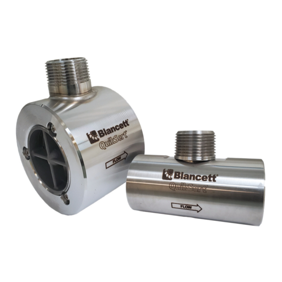
Introduction INTRODUCTION The QuikSert® explosion-proof turbine flow meter was developed for liquid applications where accuracy and dependability are of concern to the operator� The QuikSert stainless steel body incorporates a helical turbine with tungsten carbide shaft and bearings� It provides an efficient, long service life and a cost-effective solution for your measurement requirements�... - Page 6 Operating Principle Figure 2: Etching OTE: For easy reference, the meter specifications that include part number, serial number, maximum working pressure, and minimum and maximum operating temperature are etched or imprinted on the meter body� Page 6 TRB-UM-00287-EN-07 June 2020...
-
Page 7: Installation
Installation INSTALLATION Prior to installation, the flow meter should be checked internally for foreign material and to ensure the turbine rotor spins freely� Fluid lines should also be checked and cleared of all debris� The flow meter must be installed with the flow arrow, etched on the exterior of the meter body, pointing in the direction of fluid flow�... - Page 8 Installation QuikSert Turbine Flow Meter Isolation Valve 10 Pipe Diameters 5 Pipe Diameters Minimum Minimum Figure 4: Meter installation without using a bypass line This is true with any restriction in the flow line that may cause the liquid to flash� If necessary, air eliminators should be installed to ensure that the meter is not incorrectly measuring entrained air or gas�...
-
Page 9: Operational Startup
Operational Startup OPERATIONAL STARTUP The following steps should be followed when installing and starting the meter� MAKE SURE THAT FLUID FLOW HAS BEEN SHUT OFF AND PRESSURE IN THE LINE RELEASED BEFORE ATTEMPTING TO INSTALL THE METER IN AN EXISTING SYSTEM. -
Page 10: Troubleshooting Guide
Troubleshooting Guide TROUBLESHOOTING GUIDE Trouble Possible Cause Remedy • Cavitation • Increase back pressure • Debris on rotor support • Clean meter Meter indicates higher than • Build up of foreign material • Clean meter actual flow rate on meter bore •... -
Page 11: Specifications
Specifications SPECIFICATIONS Body 316/316L stainless steel Rotor CD4MCu stainless steel Materials of Bearings Tungsten carbide Construction Rotor Shaft Tungsten carbide Rotor Support 316L –150…350° F (–101…177° C) standard Temperatures to 450° F (232° C) with high-temp pickup, consult factory for Operating details Temperature... -
Page 12: Meter Parts
Meter Parts METER PARTS Magnetic Pickup (Not Included) Rotor Assembly Conduit Adapter Bushing Meter Body Thrust Ball Rotor Support Retaining Ring FLOW Figure 5: Typical cross-section of models B131C-038…B131C-100 Magnetic Pickup (Not Included) Conduit Adapter Rotor Assembly Bushing Meter Body Thrust Ball Rotor Support FLOW... -
Page 13: Part Number Information (Pickup Not Included)
Part Number Information (Pickup Not Included) PART NUMBER INFORMATION (PICKUP NOT INCLUDED) Meter Bore Approx. K- Max. Pres- Part Flow Strainer Size × Line Factor pulses/ Weight sure Drop Number Compliant Range Mesh Size (in.) US gal (psi) B131C-038 3/8 × 1 Coming soon 18,000 —... -
Page 14: Strainer Recommendations
Part Number Information (Pickup Not Included) Strainer Recommendations Part Number Strainer Mesh Clearance (in.) Filter Size B131C-038 0�0092 260 Micron B131C-050 0�0092 260 Micron B131C-075 0�0092 260 Micron B131C-088 0�0092 260 Micron B131C-100 0�0092 260 Micron B132C-050 0�0092 260 Micron B132C-075 0�0092 260 Micron... - Page 15 User Manual INTENTIONAL BLANK PAGE June 2020 TRB-UM-00287-EN-07 Page 15...
- Page 16 Control. Manage. Optimize. BLANCETT and QuikSert are registered trademarks of Badger Meter, Inc� Other trademarks appearing in this document are the property of their respective entities� Due to continuous research, product improvements and enhancements, Badger Meter reserves the right to change product or system specifications without notice, except to the extent an outstanding contractual obligation exists�...
Need help?
Do you have a question about the Blancett B134C-400 and is the answer not in the manual?
Questions and answers