
Related Manuals for Badger Meter Blancett B2800XP


Summary of Contents for Badger Meter Blancett B2800XP
- Page 1 Flow Monitor B2800XP Explosion Proof Flow Monitor Standard User Manual DSY-PM-00277-EN-03 (March 2017)
-
Page 2: Table Of Contents
Flow Monitor, B2800XP Explosion Proof Flow Monitor Standard CONTENTS Scope of This Manual Unpacking and Inspection Safety Terminology and Symbols Considerations Introduction Explosion Proof Enclosure Installation Installation Kits Operating the Monitor Buttons Modes Programming Programming Mode Run Mode Additional Scaling Parameters Flow 4 mA Setting Flow 20 mA Setting 4…20 mA Calibration... -
Page 3: Scope Of This Manual
Scope of This Manual SCOPE OF THIS MANUAL This manual is intended to help you get the B2800 flow monitor up and running quickly MPOOTANT Read this manual carefully before attempting any installation or operation. Keep the manual accessible for future reference. UNPACKING AND INSPECTION Upon opening the shipping container, visually inspect the product and applicable accessories for any physical damage such as scratches, loose or broken parts, or any other sign of damage that may have occurred during shipment... -
Page 4: Introduction
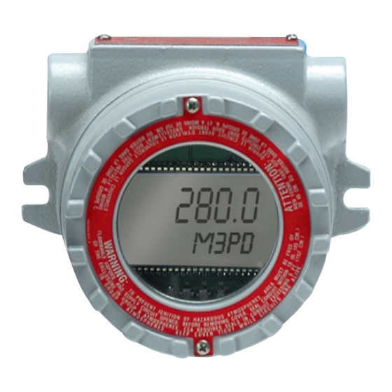
Introduction INTOODUCTION The B2800XP flow monitor is a state-of-the-art digital signal processing flow monitor designed to provide the user with exceptional flexibility at a very affordable price Though designed for use with Blancett flow meters, this display can be used with almost any flow meter producing a low amplitude AC output or contact closure signals The B2800XP flow monitor is capable of accepting a low level frequency input for calculating flow rate and total These calculations can then be displayed in the desired units of measurement The monitor’s large eight digit by 0 50 inch (12 7... -
Page 5: Installation
Installation INSTALLATION ELECTRICAL POWER MUST BE TURNED OFF BEFORE AND DURING INSTALLATION AND MAINTENANCE. 1 EIH Instrument enclosures are furnished with 3/4 inch NPT offset through feed cast hubs for conduit entries (Use Cooper Crouse-Hinds RE21-SA to reduce to 1/2 inch hubs ) 2 Secure the enclosure to the conduit system If the enclosure has mounting feet, select a mounting location that will provide sufficient strength and rigidity to support the enclosure as well as the enclosed device and wiring SELECT A MOUNTING LOCATION SO THAT THE ENCLOSURE WILL NOT BE SUBJECTED TO IMPACT BY HEAVY OBJECTS. -
Page 6: Installation Kits
Installation Kits INSTALLATION KITS To facilitate installation of the explosion proof B2800XP monitor, two sizes of installation kits are available Hub Size Kit Number Meter Sizes 1/2 in NPT Hub B280-742 3/8 in , 1/2 in , 3/4 in with 1/2 in NPT End Fittings 1 in NPT Hub B280-737 All Sizes with 1 in NPT End Fittings and Larger... -
Page 7: Operating The Monitor
Operating the Monitor OPEOATING THE MONITOO The monitor has two modes of operation referred to as the RUN mode and the PROGRAM mode Both the RUN mode and the PROGRAM mode display screen enunciators confirm the state of the monitor A quick glance at the lower left corner of the LCD screen will confirm operating status Normal operation will be in the RUN mode To access the PROGRAM mode, press MENU until the first programming screen is displayed After programming the display with the necessary information, turn on the lock out feature to prevent unauthorized access or changing the meter’s setup parameters... -
Page 8: Programming
Programming POOGOAMMING Each turbine flow meter is shipped with either a K-factor value or frequency data If frequency data is provided, the data must be converted to a K-factor before programming the monitor K-factor information, when supplied, can usually be found on the neck of the flow meter or stamped on the flow meter body The K-factor represents the number of pulses per unit of volume The K-factor is needed to program the monitor readout Programming Mode... -
Page 9: Run Mode
Programming Select the Units of Measure The monitor is programmed with five common rate/total unit options The monitor shows the rate/total unit that the display is currently set for If the current selection is correct, press ENTEO once to advance to the DISPLAY FUNCTION parameter To change the unit, press UP or OIGHT to scroll to the correct rate unit Press ENTEO to save and advance to the DISPLAY FUNCTION parameter Selection... -
Page 10: Additional Scaling Parameters
Additional Scaling Parameters ADDITIONAL SCALING PAOAMETEOS OTEE: The programming instructions below are only available for loop powered units Battery powered units do not include these programming parameters Flow 4 mA Setting Zero is the default flow rate at the 4 mA setting If the current selection is correct, press ENTEO to advance to the Flow 20 mA parameter To change the setting, press UP to increment the flashing digit and press OIGHT to move to the next digit Press ENTEO to save and advance to the Flow 20 mA parameter Flow 20 mA Setting... -
Page 11: Additional Input Options
Additional Input Options ADDITIONAL INPUT OPTIONS The Blancett flow monitor is capable of receiving magnetic pickup input or a contact closure input Since most Blancett flow meters use a magnetic pickup, the monitor is shipped configured for magnetic pickup input To change to a contact closure input, remove JP2 from the bottom two pins and jumper them to the top two pins See image below External External... -
Page 12: Maintenance
Maintenance MAINTENANCE ALWAYS DISCONNECT PRIMARY POWER SOURCE BEFORE OPENING ENCLOSURE FOR INSPECTION OR SERVICE. 1 Create a schedule for maintenance determined by the environment and frequency of use Inspect the monitor at least once a year 2 Perform visual, electrical and mechanical checks on all components on a regular basis a Visually check for undue heating evidenced by discoloration of wires or other components, damaged or worn parts, or leakage evidenced by water or corrosion in the interior b Electrically check to make sure that all connections are clean and tight, and that the device is operating correctly... -
Page 13: Troubleshooting Guide
Troubleshooting Guide TOOUBLESHOOTING GUIDE Issue Oemedy • Battery Powered Version: Check battery voltage Should be 1 5V DC Replace if low or bad No LCD display • Loop Powered Version: Check for current flow in the loop Check polarity of the current loop connections for proper orientation •... -
Page 14: Specifications
Specifications SPECIFICATIONS Battery Powered One D size, 1 5V alkaline battery Power Supply Options Loop Powered 4…20 mA loop power Battery Powered Less than 1 mA @ 1 5V DC Power Consumption Loop Powered 25 mA (maximum) Eight digit, 0 5 inch high numeric display Alphanumeric Oate and Total Display Eight character, 0 25 inch high alphanumeric display... -
Page 15: Dimensions
Dimensions DIMENSIONS ¾ NPT MENU ENTER 5 1 in 5 25 in 2 6 in 5/16 in 4 51 in (19 31 mm) (19 87 mm) (9 84 mm) (1 19 mm) (17 07 mm) PAOT NUMBEO INFOOMATION B 28 S X X - X X Units of Measure Program Level AB - Gallons... - Page 16 The Americas | Badger Meter | 4545 West Brown Deer Rd | PO Box 245036 | Milwaukee, WI 53224-9536 | 800-876-3837 | 414-355-0400 México | Badger Meter de las Americas, S.A. de C.V. | Pedro Luis Ogazón N°32 | Esq. Angelina N°24 | Colonia Guadalupe Inn | CP 01050 | México, DF | México | +52-55-5662-0882 Europe, Eastern Europe Branch Office (for Poland, Latvia, Lithuania, Estonia, Ukraine, Belarus) | Badger Meter Europe | ul.
Need help?
Do you have a question about the Blancett B2800XP and is the answer not in the manual?
Questions and answers