Sign In
Upload
Download
Table of Contents
Contents
Add to my manuals
Delete from my manuals
Share
URL of this page:
HTML Link:
Bookmark this page
Add
Manual will be automatically added to "My Manuals"
Print this page
×
Bookmark added
×
Added to my manuals
Manuals
Brands
LEYBOLD Manuals
Water Pump
ECODRY plus 25
Operating instructions manual
LEYBOLD ECODRY plus 25 Operating Instructions Manual
Multi-stage roots vacuum pump
Hide thumbs
1
2
Table Of Contents
3
4
5
6
7
8
9
10
11
12
13
14
15
16
17
18
19
20
21
22
23
24
25
26
27
28
29
30
31
32
33
34
35
36
37
38
39
40
41
42
43
44
45
46
47
48
49
50
51
52
53
54
55
56
57
58
59
60
61
62
63
64
page
of
64
Go
/
64
Contents
Table of Contents
Bookmarks
Table of Contents
Table of Contents
1 Safety and Compliance
Definition of Warnings and Cautions
Safety Symbols
2 General Description
Overview
Pump Controller
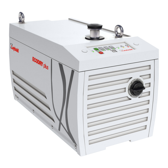
Figure 1. General View
Interface Control Panel
Auxiliary Connector Socket
Figure 2. Interface Control Panel
Logic Interface
Gauge Connection
Figure 3. Valve Connector
Auto-Run
Pump Controller Configuration
Figure 4. Gauge Connection
3 Technical Data
Operating and Storage Conditions
Mechanical Data
Performance
Figure 5. Dimensions
Materials Exposed to Gases Pumped
Electrical Data
Figure 6. Performance Graph
4 Installation
Unpack and Inspect
Mechanical Installation
Leak Test the System
Electrical Installation
Pump Voltage Setting
Figure 7. Voltage Selection Plate
Connect the Electrical Supply
Connection for Remote Control and Monitoring
5 Commission the Pump
6 Operation
Operation Safety
Operational Modes
Control Panel Interface
Logic Interface Data
Parallel Control and Monitoring
X1 Control Interface
Analogue Speed Control
Figure 8. ECODRY Plus X1 SUB-D 9 (Male) START / STOP and STANDBY Operation Configuration
Operational Modes
Figure 9. ECODRY Plus X1 SUB-D 9 (Male) Speed Control
Figure 10. Analogue Speed Control
Start the Pump
Shut down the Pump
Restart the Pump
X104 SUB-D9 (Female) Serial RS-485 Interface
MODBUS RTU Protocol
Physical Layer
Data Link Layer
Application Protocol Layer
ECODRY Plus Protocol
Register Addresses
Gas Ballast Operation
Gas Ballast Adaptor Fit
Extra Silencer Removal
Mounting Kit Use
Pressure Gauge Connectivity and Automatic Eco-Mode
7 Maintenance and Service
General Maintenance
Maintenance Plan
Inspect and Clean the Inlet Strainer
Clean the External Fan Grill
Replace the Pump Bearings
Replace the Pump Controller
Electrical Safety Check
Service Indicator Codes
8 Service
Leybold Service
9 Fault Finding
Alarm Indicator Codes
10 Storage
Advertisement
Quick Links
1
Interface Control Panel
2
Maintenance and Service
3
Alarm Indicator Codes
Download this manual
ECODRY plus
Multi-stage roots vacuum pump
Operating instructions 300902516_002_C0
162025V001
162035V001
Table of
Contents
Previous
Page
Next
Page
1
2
3
4
5
Advertisement
Table of Contents
Need help?
Do you have a question about the ECODRY plus 25 and is the answer not in the manual?
Ask a question
Questions and answers
Related Manuals for LEYBOLD ECODRY plus 25
Water Pump Leybold RUVAC WS 251 Operating Instructions Manual
(26 pages)
Water Pump LEYBOLD ECODRY plus 35 Operating Instructions Manual
Multi-stage roots vacuum pump (64 pages)
Water Pump LEYBOLD SOGEVAC SV40 B Operating Instructions Manual
Single-stage, oil-sealed rotary vane pump (45 pages)
Water Pump LEYBOLD RUVAC WS251 Installation And Operating Instructions Manual
Roots vacuum pump with mineral oil, synthetic oil or pfpe-filling (52 pages)
Water Pump LEYBOLD ECODRY Plus Operating Instructions Manual
Multi-stage roots vacuum pump (30 pages)
Water Pump LEYBOLD TRIVAC B Series Operating Instructions Manual
Rotary vane vacuum pump atex categories 3 i and 3 i/o with mineral oil (70 pages)
Water Pump LEYBOLD MAG Series Operating Instructions Manual
Turbomolecular pumps with magnetic bearing, electronic frequency converter (112 pages)
Water Pump LEYBOLD SOGEVAC SV200 FP Original Operating Instructions
Single-stage, oil-sealed rotary vane pump (44 pages)
Water Pump LEYBOLD RUVAC RA Series Operating Instructions Manual
(26 pages)
Water Pump LEYBOLD MAG integra Series Installation & Operating Instructions Manual
Turbomolecular pumps with magnetic bearing and frequency converter (52 pages)
Water Pump Leybold SOGEVAC SV40 BI FC Original Operating Instructions
Single-stage, oil-sealed rotary vane pump (30 pages)
Water Pump LEYBOLD DRYVAC DV 650 Operating Instructions Manual
Dry compressing vacuum pumps (96 pages)
Water Pump LEYBOLD SCREWLINE SP 630 F Operating Instructions Manual
Dry compressing screw vacuum pump (82 pages)
Water Pump LEYBOLD SOGEVAC SV45 FP Original Operating Instructions
Single-stage, oil-sealed rotary vane pump (40 pages)
Water Pump Leybold ScrewLine SP250 Operating Instructions Manual
Dry compressing screw vacuum pump (76 pages)
Water Pump LEYBOLD TURBOVAC 151 Operating Instructions Manual
Turbomolecular pumps with external frequency converter (44 pages)
This manual is also suitable for:
Ecodry plus 35
Ecodry plus 45
Ecodry plus 70
Table of Contents
Print
Rename the bookmark
Delete bookmark?
Delete from my manuals?
Login
Sign In
OR
Sign in with Facebook
Sign in with Google
Upload manual
Upload from disk
Upload from URL


Need help?
Do you have a question about the ECODRY plus 25 and is the answer not in the manual?
Questions and answers