
Related Manuals for LEYBOLD MAG Series


Summary of Contents for LEYBOLD MAG Series
-
Page 1: Operating Instructions
OPERATING INSTRUCTIONS GA05141_0702 LINE Turbomolecular Pumps with Magnetic Bearing digital MAG.DRIVE Electronic Frequency Converter vacuum... -
Page 2: Table Of Contents
Contents Section Page General safety information ........4 Description . - Page 3 Service at Leybold’s ........
-
Page 4: General Safety Information
Consult local, state, and national agencies regarding specific requirements and regulations. Address any further safety, operation and/or mainte- nance que-stions to your nearest Leybold Vacuum office. Warning Never expose any parts of the body to the vacuum. - Page 5 Safety information Parts of the pump can become so hot during operation (> 70 °C, Warning > 158 °F) that they represent a burn hazard: Provide protection against contact with the hot components. Warning The converter has dangerous voltage levels. Failure to strictly follow the instructions in this Manual can result in death, severe bodily injuries or significant material damage.
- Page 6 Figures The references to diagrams, e. g. (1/2) consist of the Fig. No. and the Item No. in that order. We reserve the right to alter the design or any data given in these Operating Instructions. The illustrations are not binding. Retain the Operating Instructions for further use.
-
Page 7: Description
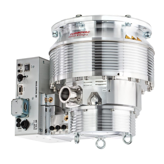
Description Description System overview The Leybold MAG pumping system consists of: The MAG turbo pump The MAG are turbomolecular pumps utilizing magnetic bearings.They are designed to evacuate vacuum chambers down to pressure values in the high-vacuum range and to pump high gas throughputs. - Page 8 Description MAG 1500 CT MAG W 830 C MAG W 1500 CT MAG W 1300 C MAG W 2200 C MAG W 2800 CT MAG W 3200 CT Fig. 1 MAG turbopumps Each Fuse 4 A digital digital Fig. 2 MAG.DRIVE Front panel GA05141_0702 - 09/2004...
-
Page 9: Compatibility With Pumped Media
All materials used inside the pump are compatible with typical gases used Materials for semiconductor processes. Caution Please consult Leybold for recommendations on pump models for specific processes and application requirements. Corrosion protection Purge gas To protect the pump from corrosive gases it is mandatory to use dry Nitrogen purge during operation of the pump.The purge gas protects the... -
Page 10: Design Of The Mag
Description Design of the MAG The MAG comprises basically the pump housing, the multistage rotor with the stator package, the drive, and a magnetic bearing. Rotor The rotor is made from a high strength aluminium alloy. The rotor and the Ceramic layer lower stator plates are protected with a special ceramic layer ( KEPLA- COAT... - Page 11 Description Motor Standard rotor Wide range rotor Fig. 3 Section of a MAG GA05141_0702 - 09/2004...
-
Page 12: Function And Design Of The Mag.drive Digital
Description Function and design of the digital MAG.DRIVE digital The MAG.DRIVE electronic converter is used to drive the MAG pumps from MAG 830 to MAG 3200. The electronic converter converts the single-phase line supply voltage into DC motor. a three-phase DC voltage to control and monitor the electronically-com- mutated DC motor. - Page 13 Description Each Fuse 4 A digital digital MAG.DRIVE Each Fuse 4 A Prog Enter Start Stop digital digital MAG.DRIVE with Plug-in control Fig. 4 Front panel X14 Connection control plug X19 Mains connection X20 Connection magnetic bearing / pump motor / (X22) memory chip X21 Connection TMS / purge gas...
-
Page 14: Standard Specification
Description Standard specification The turbomolecular pumps are shipped complete, sealed in a PE bag con- taining a desiccant. The maximum effective life time of the desiccant is one year. The intake flange is sealed with a transport seal, the forevacuum flange with a plastic cap. -
Page 15: Technical Data
Description Technical data W 830 C W 1300 C W 1300 C High-vacuum flange 160 ISO-F 200 ISO-F 250 ISO-F 250 ISO-K Pumping speed (PNEUROP) for N l·s 1100 1220 for Ar l·s 1050 1180 for H l·s 1020 Compression for N >... - Page 16 Description Technical data (continued) 1500 CT W 1500 CT 1500 CT W 1500 CT High-vacuum flange 200 ISO-F 200 ISO-F 250 ISO-F 250 ISO-F 200 CF Pumping speed (PNEUROP) for N l·s 1100 1100 1220 1220 for Ar l·s 1000 1050 1180 1180...
- Page 17 Description Technical data (continued) W 2200 C W 2200 C W 2800 CT W 3200 CT High-vacuum flange 200 ISO-F 250 ISO-F 250 ISO-F 320 ISO-F Pumping speed for N l·s 1600 2000 2650 3200 for Ar l·s 1450 1900 2450 3000 for H...
- Page 18 Description Technical data (continued) W 830 W 1300 W 2200 W 2800 High-vacuum flange 160 CF 200 CF 250 CF 250 CF Pumping speed for N measured without splinter guard (PNEUROP) l·s 1170 1800 2400 Compression for N 1.5 · 10 1.5 ·...
- Page 19 Description Technical data (continued) Purge gas Section 2.6 digital MAG.DRIVE Voltage range 200 - 240 V +10% -15% Line supply frequency 50 / 60 Hz Load Stand-by approx. 100 W Maximum heated pumps 1800 W Maximum non-heated pumps 1100 W Max.
- Page 20 Description 3500 With purge gas MAG W 3200 CT DN 320 with splinter guard Forepump 100 m 3000 Pipe 1 m DN 40 MAG W 2800 C/CT DN 250 according to PNEUROP 2500 MAG W 2200 C DN 250 2000 MAG W 2200 C DN 200 1500 MAG (W) 1300 / 1500 C/CT DN 250...
-
Page 21: Ordering Data
Description Ordering data Part No. Pumps see Table “pumps” Seal Kit DN 250 metal 200 07 901 Seal Kit metal for other flanges on request digital MAG.DRIVE converter 400035V0011 Plug-in control 121 36 Connecting cables, converter — pump see Fig. 8 19“... -
Page 22: Pump Configuration
Description GA05141_0702 - 09/2004... - Page 23 Description 0° 0° 90° 270° 90° DRIVE/BEARING connection connection DRIVE/BEARING connection 225° 180° 180° Cable DRIVE/BEARING Cable Converter cable outlet Pump cable outlet length DRIVE/BEARING X20 DRIVE/BEARING X23 PK X24 Part No. 1.5 m bended 225° straight straight 400036V0001 1.5 m straight straight straight...
- Page 24 Description max. 115 straight plugs bended plugs Ø 3.3 Each Fuse 4 A 122.4 digital Fig. 9 Dimensional drawing of the MAG.DRIVE ; dimensions in mm t u s S t a 19“ installation frame I V E 4 x M3 screws digital Fig.
- Page 25 Description MAG W 830 C MAG W 1300 C Inlet flange A Forevacuum connection MAG W 830 C 160 ISO-F 225 15° 45° DN 40 KF MAG W 1300 C 200 ISO-F 285 15° 30° DN 40 KF / DN 25 KF MAG W 1300 C 250 ISO-F 335 15°...
- Page 26 Description MAG (W) 1500 CT Ø A Ø B Ø C Inlet flange 200 ISO-F 30° 15° 250 ISO-F 30° 15° 200 CF 15° 7.5° Ø 262 DN 40 KF 164.5 Ø175 M8, 15 mm deep M8, 15 mm deep Fig.
- Page 27 Description MAG W 2200 C, Part No. 400081V0011 400081V0021 Inlet flange 200 ISO-F 250 ISO-F Ø 317 DN 40 164.6 Ø 199 Fig. 13 MAG W 2200 C, dimensions in mm GA05141_0702 - 09/2004...
- Page 28 Description MAG W 2200 C, Part No. 400081V0020 Ø335 Ø283 Ø301 Ø317 Ø199 G1/8" Fig. 14 MAG W 2200 C, dimensions in mm GA05141_0702 - 09/2004...
- Page 29 Description MAG W 2800 CT, MAG W 3200 CT Inlet flange 250 ISO-F 320 ISO-F 13.5 Ø 369 DN 40 196.5 Fig. 15 MAG 2800 CT and MAG 3200 CT, dimensions in mm GA05141_0702 - 09/2004...
- Page 30 Description MAG W 830 Ø 202.5 DN 160 CF Ø 260 Ø 175 Bearing Connector Ø 8.4 85.5 Fig. 16 MAG W 830, dimensions in mm GA05141_0702 - 09/2004...
- Page 31 Description MAG W 1300 Ø253 DN 200 CF Ø260 Ø175 Bearing Connector Fig. 17 MAG W 1300, dimensions in mm GA05141_0702 - 09/2004...
- Page 32 Description MAG W 2200 Ø 305 DN 250 CF DN 40 KF Ø199 Bearing Connector Fig. 18 MAG W 2200, dimensions in mm GA05141_0702 - 09/2004...
- Page 33 Description MAG W 2800 Ø305 DN 250 CF Ø369 Ø199 Ø8.4 DN 40 KF Bearing Connector Fig. 19 MAG W 2800, dimensions in mm GA05141_0702 - 09/2004...
-
Page 34: Installation
Installation Installation MAG W 830 C High-vacuum flange Forevacuum flange connection DRIVE/BEARING Purge gas in connection Cooling water connection Correct 17 mm 35 mm Wrong Caution 8 bolts M10 x 35 Install the splinter guard as shown. Installing the Installation torque per bolt 35 splinter guard upside down may lead to contact Bolt quality:12.9 according to EN ISO 898-1 between splinter guard and rotor during fast... - Page 35 Installation MAG W 1300 C High-vacuum flange Forevacuum flange Cooling water connection connection DRIVE/BEARING Purge gas in connection ISO-F flange DN 200: 260 mm DN 250: 310 mm Correct DN 200: 213 mm DN 250: 261 mm 14 mm 35 mm Wrong ISO-K flange Caution...
- Page 36 Installation MAG (W) 1500 CT High-vacuum flange Heater band Forevacuum flange Purge gas valve Cooling water connection Purge gas in DRIVE/BEARING connection connection connection Correct DN 200 CF 10 mm 24 bolts M8 x 40 2 mm Installation torque per bolt 25 40 mm Bolt quality: 10.9 according to 48 mm...
- Page 37 Installation MAG W 2200 C High-vacuum flange Forevacuum flange Cooling water DRIVE/BEARING connection connection Purge gas in PK connection PK connection Cooling water connection DRIVE/BEARING connection Purge gas in DN 200: 260 mm DN 250: 310 mm Housing Splinter guard Ring DN 200: 213 mm DN 250: 261 mm...
- Page 38 Installation MAG W 2800 C, CT High-vacuum flange Heater band Forevacuum flange Purge gas valve Purge gas in Cooling water connection DRIVE/BEARING connection connection connection 310 mm Housing Splinter guard Ring 261 mm 15.5 mm 35 mm 12 bolts M10 x 35 Installation torque per bolt 35 Bolt quality:12.9 according to EN ISO 898-1 with coating...
- Page 39 Installation MAG W 3200 CT High-vacuum flange Heater band Forevacuum flange Purge gas valve Purge gas in Cooling water connection DRIVE/BEARING connection connection connection 395 mm Housing Splinter guard Ring 318 mm 14 mm 40 mm 10 bolts M12 x 40 Installation torque per bolt 45 Bolt quality:12.9 according to EN ISO 898-1 with coating...
- Page 40 Installation MAG W 830 High-vacuum flange Forevacuum flange connection DRIVE/BEARING Purge gas inlet connection (blind flanged) Cooling water connection Correct 10 mm 2 mm 40 mm 48 mm Wrong DN 160 CF: 20 bolts M8 x 40 Installation torque per bolt 25 Caution Bolt quality: 10.9 according to Install the splinter guard as shown.
- Page 41 Installation MAG W 1300 High-vacuum flange Forevacuum flange connection DRIVE/BEARING connection Purge gas inlet (blind flanged) Cooling water connection Correct 10 mm 2 mm 40 mm 48 mm Wrong DN 200 CF: 24 bolts M8 x 40 Installation torque per bolt 25 Caution Bolt quality: 10.9 according to Install the splinter guard as shown.
- Page 42 Installation MAG W 2200 High-vacuum flange Forevacuum flange Purge gas inlet (blind flanged) Cooling water connection connection DRIVE/BEARING connection Correct 10 mm 2 mm 40 mm 48 mm Wrong DN 250 CF: 32 bolts M8 x 40 Installation torque per bolt 25 Caution Bolt quality: 10.9 according to Install the splinter guard as shown.
- Page 43 Installation MAG W 2800 High-vacuum flange Forevacuum flange Cooling water connection connection DRIVE/BEARING connection Purge gas inlet (blind flanged) Correct 10 mm 2 mm 40 mm 48 mm Wrong DN 250 CF: 32 bolts M8 x 40 Installation torque per bolt 25 Caution Bolt quality: 10.9 according to Install the splinter guard as shown.
-
Page 44: Unpacking - Storing - Transportation
Keep the packaging ging. Make sure that the product has not been damaged during transpor- tation. If this unit is damaged contact your carrier and inform Leybold if necessary. For storage of the product, use the packaging provided. Lift the pump by the crane eyelets. -
Page 45: Connecting The Mag To The Vacuum Chamber
If the pump should suddenly seize, a high decceleration torque will have to be absorbed by the system. To accomplish this, use all bolts provided by Leybold for fastening the high-vacuum flange or use bolts of the prescribed quality; see also the Fig. 20 to 29 and 31 to 33. - Page 46 Installation DN 160 ISO-F: 8 bolts M 10 x 50 Installation torque per bolt 35 +5 Nm ISO-F flange DN 200/250 ISO-F: 12 bolts M 10 x 50 Vacuum sealing disk consisting Installation torque per bolt 35 +5 Nm of centering ring and O-ring with outer support ring DN 320 ISO-F: 10 bolts M 12 x 50 Installation torque per bolt 45 +5 Nm...
- Page 47 If several turbomolecular pumps are installed to the vacuum chamber of the Vibration influence same system, there is the risk of interference (vibration interference bet- ween the pumps). If such a risk exists please contact Leybold Vacuum Application Support. We recommend installing an isolation valve between the pump and the Isolation valve chamber.
-
Page 48: Connecting The Backing Pump
Installation Turbomolecular pump Forevacuum gauge point Backing pump Anti-vibration bellows Forevacuum valve High vacuum valve Purge gas connection Valve in the roughing line Electronic frequency converter — — — — roughing line; recommended if shorter cycle times are to be achieved —... - Page 49 Installation M < 150 Nm < 150 Nm Fig. 35 Maximum torques for the forevacuum connection The forevacuum line must be tight. Hazardous gases can escape Warning at leaks or the gases being pumped can react with the air or humi- dity.
-
Page 50: Connecting The Cooling Water
Installation Pump cooling Bypass Fig. 36 Schematic of the cooling water flow for MAG (W) 1500, 2800, 3200 CT Connecting the cooling water Cooling water specifications Inlet temperature 10 - 30 °C Inlet pressure 2 to 7 bar absolute Cooling water requirement See Fig. - Page 51 Installation Swagelock tube fitting Stainless steel for tube 1/4“ hose nipples 1/2“ John Guest fitting Thread G 1/8“ for hose 6 mm OD Swagelock tube 1/4“ Swagelock tube 1/4“ (bended) Swagelock tube 1/4“ Ø 1/4“ (6.4 mm) Cooling water Cooling water Do not mix up the inlet and the outlet! Fig.
- Page 52 Installation Operation window °C Temperature MAG (W) 1500/2800/3200 CT: Bypass operation All pumps: Cooling Differential pressure between inlet and outlet Fig. 38 Recommended cooling water flow GA05141_0702 - 09/2004...
-
Page 53: Connecting The Purge Gas
Installation Connecting the purge gas Please contact Leybold for assistance in making the decision as to which media can be pumped with or without purge gas. In processes which require purge gas the pump will have to be vented, when it is switched off, through the purge gas port. - Page 54 Installation Pumps with purge gas valve (MAG (W) 1500 CT, W 2200 C, W 2800 C/CT, W 3200 CT) The MAG is equipped with a purge gas and venting valve. It is controlled digital by the MAG.DRIVE The purge gas and vent valve regulates the flow of purge gas, at supply pressures of between 1.5 and 6.0 bar (absolute), to the pump, keeping pressure at a constant value provides for safe pump venting.
- Page 55 Installation upper magnetic bearing Motor lower magnetic lower magnetic bearing bearing 24 V Sensor PVW 2,4 Fig. 39 Purge gas and vent valve assembly and turbomolecular pump (schematic) GA05141_0702 - 09/2004...
- Page 56 Installation Purge gas Choke (capillary) Venting gas To purge gas inlet of MAG W 830 and MAG W 1300 Fig. 40 Schematic drawing of the purge gas Tee MAG W 1300 C, Part No. 400110V0017: Purge gas connection with capil- lary for flow reduction to 36 sccm at 1.5 bar abs.
- Page 57 Installation G 1/4" Filter mounted: O-ring in the groove Purge gas or air MAG W 2200 C with purge gas connection 1/4“ thread Fig. 42 Mounting the purge gas filter to the pump GA05141_0702 - 09/2004...
-
Page 58: Installing The Mag.drive Digital
Installation digital Installing the MAG.DRIVE The converter can be installed in a 19” cabinet. It is 1/2 of 19“ wide and has 3 height units. For easier installation we offer an installation frame; see Section 1.7. If you use this installation frame, remove the converter’s rub- ber feet when installing the converter. -
Page 59: Power Supply Connection X19
(EMC) Directives of the EC. In order to maintain this the following installa- tion instructions must be observed: To connect the pump to the converter the prescribed Leybold cables must be used. The connection cables to the analog interface (control plug X14) and to the serial interface (connector X7) must be shielded. -
Page 60: Control Plug X14
Installation 2.7.3 Control plug X14 Emergency off Make sure that pins 47 and 48 are connected via a jumper if you don’t con- nect an emergency off switch. A plug for the control plug X14 with a jumper connected between pins 47 and 48 is included in the standard specification. - Page 61 Installation X14 50 pole Sub-D I/O PIN SIGNAL Relay 1 n.o. FAILURE 18 Relay 1 com. FAILURE 34 Relay 1 n.c. FAILURE Relay 2 n.o. NORMAL 19 Relay 2 com. NORMAL 35 Relay 2 n.c. NORMAL OPERATION OPERATION OPERATION Relay 3 n.o. WARNING 20 Relay 3 com.
-
Page 62: Interface Connector
27 or 43) is connected at the digital input. 2.7.4 Interface connector A 9-pin sub-D socket is provided at the front panel. The connector X7 is assigned the serial interface RS 232. It is only to be used by the Leybold Service. GA05141_0702 - 09/2004... - Page 63 Installation Pumps with TMS DRIVE/BEARING MAINS Control plug Pumps without TMS DRIVE/BEARING MAINS Control plug Pumps with optional purge vent valve DRIVE/BEARING Purge Vent Purge/Vent MAINS Control plug Fig. 46 Block wiring diagram GA05141_0702 - 09/2004...
- Page 64 Installation Relay 1 Failure X14.18 No failure X14.1 X14.34 Start command applied Relay 2 Normal Operation & X14.19 Actual frequency X14.2 Normal operation X14.35 Relay 3 Warning Warning X14.20 X14.3 X14.36 Relay 4 Acceleration Acceleration X14.21 X14.4 X14.37 Relay 5 Deceleration Deceleration X14.22 X14.5...
- Page 65 Installation Motor- or bearing- temperature Threshold Motor current Function Threshold signal relay Act. frequency Relay 6/7/8/9 Option Threshold X14.23/24/25/26 No cooling water No purge gas X14.6/7/8/9 TMS temp. o.k. X14.39/40/41/42 Venting Pump standstill Start command Power supply o.k. Power failure Stand-by Function analog output...
-
Page 66: Operation
Operation Operation General operation rules The magnetic bearing in the MAG are immune to wear. In addition to the magnetic bearings, the MAG is equipped with touch-down bearings which protect the rotor against mechanical contact with the stator if the pump is Protecting the subjected to external shock loading or when the pump is switched off. - Page 67 Operation mbar Time/s Fig. 50 Curve for safe venting of the MAG; pressure rise as a function of venting time Venting As to suitable gases, see Section 2.6. Venting Method The pump must be vented via the purge gas and venting valve or the vent port when shutting the pump down.
-
Page 68: Temperature Management System
The temperature (TMS) setpoint can be programmed via the front panel keys at every time. Principally the factory presetting will be used. The setting is saved in the pump’s memory chip. Before changing any setpoint value request Leybold! For the setting refer to 3.10.6 Operating menu, Set TMS. Heat up The setpoint temperature will be reached within 30 to 60 minutes depen- ding on cooling and environmental conditions. - Page 69 Operation T +5 K T +2 K T +1 K T set T –1 K T –5 K TMS Code 3 4 3 6 4 6 Heater ON Cooling ON Warning Signal TMS OK digital Fig. 51 Typical function diagram TMS for the MAG.DRIVE TMS status code The TMS status code is displayed on the operation display.
-
Page 70: Power Control System (Pcs)
Continuous operation at a high motor current will reduce the ser- vice life of the rotor. In such cases additional safety measures need to be introduced which must be co-ordinated with Leybold. Also warming up of the rotor due to other influences will reduce its service life, for example, pumping of hot process gases. -
Page 71: Bakeout
Operation Bakeout Only for pumps with CF flange If pressures in the range of 10 mbar or below are to be developed, the vacuum chamber and the components installed therein will have to be baked out. Protect the rotor against intensive, direct heat radiation. When baking out at the forevacuum side –... -
Page 72: Operation With The Start And Stop Keys
Operation Operation with the START and STOP keys Switching on digital Switch on the MAG.DRIVE The MAIN LED lights green. Wait for approximately 20 to 30 seconds until the MAG.DRIVE has been initiated. If the pump has the optional TMS (including e.g. the red heater band) the heater will be activated. -
Page 73: Remote Control
Operation Remote X14.11 Remote X1.1 Start X14.12 Start X1.2 X14.10 Masse X1.3 Switch closed: START Switch open: STOP Fig. 52 Connecting-up example remote control Significance of the lamps (green) Is lit if communication has been established via the interface. STATUS (green/red) Red, steady light = Failure... - Page 74 Operation +15 V ~ 3 kOhm X14.48 Shutdown X14.47 X14.11 Operating mode: REMOTE 0 V = 0 Programming only via 15 V = 1 X14.12 serial interface START Start delay time X14.10 START interface START & pump START key pad STOP key pad ≥1...
-
Page 75: Operation With Plug-In Control
Plug-in control Operation with plug-in control Observe the general operation rules given in Section 3.1 to 3.5. Switching on digital Switch on the MAG.DRIVE . The display reads after approximately 20 to 30 seconds Ready 0.0 A 0 Hz If the pump has the optional TMS (including e.g. the red heater band) the heater will be activated. -
Page 76: Operating Statuses
Plug-in control Switching off digital The MAG.DRIVE controls the venting automatically provided purge gas digital is connected to the MAG and the MAG.DRIVE is programmed corre- spondingly (“Vent on”). Press the STOP key. Deceleration 15.0 A 400 Hz will be displayed. When the display reads Ready 0.0 A 0 Hz... - Page 77 Plug-in control Function Returns to the operating display from the storage procedure without storage. Returns to the operating display from any point of the basic menu. Acceleration 14.5A 254Hz HOK No function Prog Selects the programming menu from the operating display. Confirms to store changed parameters to the EEPROM Prog Enter...
- Page 78 Plug-in control Stand-by operation The pumping system can be operated in a stand-by mode with reduced speed. The speed can be set in the operating menu “pump”. The function stand-by can be activated with the digital inputs option 1 or 2. Do not use at the same time the stand-by function and the speed con- trol via the analog input.
- Page 79 Plug-in control Mains switched on Initialization Switch On Guard After a failure, quit a second time Ready START command STOP command Start Delay Mains ok Mains failure Acceleration Frequency > P 25 x P24 Mains failure Option Mains Down Normal Operation Stand-by command >...
-
Page 80: Operating Menu
Plug-in control 3.10 Operating menu 3.10.1 Basic Menu Menu item Description Adjustable value / option Ac- cess min. max. stan- Unit value value dard Ready 0.0 A 0 Hz Ready Operating display Enter Freq. Setpoint Freq. Setpoint Sets the speed for operation Hz r/w on 600 Hz !! Every change is directly written... -
Page 81: Menü System Info
Plug-in control 3.10.2 Menü System Info System Info Enter Menu item Description Adjustable value / option Ac- Real-Time Clock cess 99.12.31 23:59 min. max. Unit Enter value value fault Product Name Real-Time Clock Real-Time Clock actual value - MD Digital 99.12.31 23:59 Format: YY.MM.DD HH:MM Enter... -
Page 82: Menu Failure Storage
Plug-in control 3.10.3 Menu Failure Storage Menu item Description Adjustable value / option Ac- cess min. max. Unit Failure Storage value value fault Failure Total No. of total failures since actual value Enter 65535 manufacturing date Failure Total 65535 Failure TMS No. -
Page 83: Menu Set Converter
Plug-in control 3.10.4 Menu Set Converter Set Converter Menu item Description Adjustable value / option Ac- Enter cess Relay 6 Option min. max. stan- Unit Bearing Temp. value value dard Motor Current Frequency Relay 6 Option Relay with change-over contact; r/w on No Cooling Water the operator can select one of... -
Page 84: Menu Set Pump
Plug-in control 3.10.5 Menu Set Pump Menu item Description Adjustable value / option Ac- Set Pump cess min. max. Unit Enter value value fault Normal Operation Normal Operation Threshold for normal operation 95 % corresponding to the Standby % r/w off Enter frequency setpoint Setpoint... -
Page 85: Frequency Settings
Plug-in control General Sequence Default Values 490 Hz = Maximum Frequency 490 Hz = Maximum Frequency = Freq. Setpoint Normal Operation Threshold 465.5 Hz = (95 % of Freq. Setpoint) Freq. Setpoint Normal Operation Threshold (xx to 99 % of Freq. Setpoint) Standby Setpoint with 20 Hz Hysteresis 250 Hz = Standby Setpoint with 20 Hz Hysteresis 200 Hz = Minimum Frequency... - Page 86 Plug-in control Table A “Option relays” Function of the option relays Refer to Set Converter/Relay option (section 3.10.4). There are 4 option relays (relay 6...9) with change-over contact; the operator can select one of the functions described in the following table. If the condition of the selected functions is performed, the selected relay switches over.
- Page 87 Plug-in control Table B “Parameters for the analog output” Typical parameter numbers Parameter Description min value max value unit Frequency 1000 motor current 0.1 A power 6553.5 0.1 W motor temp. °C converter temp. 1000 °C TMS temp. °C bearing temp. °C cooling temp.
-
Page 88: Total View Of The Menu
Plug-in control 3.10.9 Total view of the menu Basic menu Failure Storage Ready System Info 0.0 A 0 Hz Enter Enter Enter Failure Total Freq. Setpoint Real-Time Clock 600 Hz 65535 99.12.31 23:59 Enter Enter Enter Failure TMS Motor Temp. Product Name 65535 50 °C... - Page 89 Plug-in control Programming menu Set Converter Set Pump Set TMS Set Purge/Vent Enter Enter Enter Enter Relay 6 Option Normal Operation TMS Setpoint Purge/Vent Bearing Temp. 95 % 70 °C Purge OFF Motor Current Purge ON Enter Enter Frequency Via X14 Max.
-
Page 90: Maintenance
Under these conditions the rotor can not be controlled by the magnet bearing and the pump will have a full run down on the touch- down bearing. Only the Leybold service can change the touch-down bearings. GA05141_0702 - 09/2004... -
Page 91: Cleaning The Frequency Converter Internally
Such contamination may lead to malfunctions, overheating or short circuits. Therefore the converter must be cleaned after 5 years. Only the Leybold service can clean the converter internally. Removing the pump from the system MAG which have been used in semiconductor processes are contamina- ted by semiconductor process gases. -
Page 92: Service At Leybold's
Particularly protect the flanges, the cooling water connectors and the cur- rent feedthrough. Service at Leybold’s If you send a pump to Leybold indicate whether the pump is free of sub- Contamination stances damaging to health or whether it is contaminated. If it is contami- nated also indicate the nature of hazard. - Page 93 Maintenance bolts collar flange retaining ring blank flange Centering ring with O-ring desiccant nuts desiccant centering ring with O-ring clamping ring blank flange screw cap with O ring polyethylene bag with cable tie Fig. 58 Sealing the MAG tightly with the metal seal kit GA05141_0702 - 09/2004...
-
Page 94: Troubleshooting
Troubleshooting Troubleshooting In case of a malfunction, the MAG will be braked and the first line of the display shows FAILURE Malfunction messages can be cancelled once the pump has come to a stop and after the malfunction has been rectified; do so with the STOP function (button or remote control). -
Page 95: Warning Messages
Section 3.10.1. Temperature sensor inside Reduce gas load. If the warning persists con- the motor reads a higher tact Leybold service. temperature value than the warning threshold (130 °C). Drive failure or internal converter failure. Contact Leybold service. - Page 96 PK Communication BEARING cable damaged or not connec- Check BEARING connector and cable for ted. damages or bent pins. Contact Leybold servi- Converter does not commu- ce if the cable is damaged. nicate with the memory chip of the pump.
-
Page 97: Failure Messages
Check pump connector X23. In particular measure resistance between pins X23/CC and X23/BB. The resistance is typically 2kΩ ± 1 %. In case of abnor- mal values (> 3.4 kΩ) are measured contact Leybold service. BEARING cable or connector dama- Step 2: Check BEARING cable ged. - Page 98 0 and BEARING cable or connector damaged. Check BEARING connector and cable for bent 5 Hz. The code designates pins. Contact Leybold service if the cable is the affected axis. damaged. Vibration influence of several pumps bet- Consult Leybold Application Support.
- Page 99 Measure the resistance between pins 1 and ted. 3of the cooling water temperature sensor. The cooling water temperatu- Contact Leybold if the resistance of the sensor re sensor reads a temperatu- is under 100 Ω. re lower than 1 °C.
- Page 100 Check pump connector X23. In particular ted. measure the resistance between pins X23/q The magnetic bearing tempe- and X23/R. Contact Leybold if the resistance rature sensor reads a tempe- of the sensor is under 100 Ω. rature lower than 1 °C.
- Page 101 The converter measures a Heating element defective. Repeat step 2of failure TMS 1. In case the measured heating current of more than value is less than 60 Ω contact Leybold service. 4 A. Converter failure. Contact Leybold service. TMS 3 TMS sensor damaged.
- Page 102 Measure the resistance between pins 1 and 3 of the cooling temp. sensor.The resistance is typical- ly between 110 and 150 Ohm (20°C to 140°C). Contact Leybold Service if the sensor is defective. AMB Not Initial Drive / Bearing Cable is not con- Check cable connections.
-
Page 103: Malfunctions
Display malfunction, confu- Converter failure. Switch the converter off and on again. If the sing messages. No reaction converter still malfunctions contact Leybold when pressing keys. service. Vacuum chamber pressure Purge gas and venting valve open or Open and close purge gas and/or venting rises above normal backing malfunctioning. -
Page 104: Ec Manufacturer's Declaration
Appendix IIb to the 98/37/EG Machinery Guidelines We - LEYBOLD Vacuum GmbH - herewith declare that operation of the incomplete machine defined below, is not permissible until it has been determined that the machine into which this incomplete machine is to be installed, meets the regulations of the EEC Directive on Machinery. -
Page 105: Ec Conformance Declaration
EC Conformance Declaration We, the Leybold Vacuum GmbH, declare herewith that the products listed below, in the embodiment which we have placed on the market, comply with the applicable EC guidelines. This declaration becomes invalid if modifications are made to the product without consultation with us. - Page 106 digital The system MAG LINE turbomolecular pump connecting cables frequency converter has been tested by the TÜV Rheinland of North America according to the requirements of NRTL (used standards UL 61010A-1 and IEC 61010-1/A2) and SEMI S2 The components are in compliance to the tested standards. Certificate No.
- Page 107 Notes GA05141_0702 - 09/2004...
- Page 108 I / we hereby declare that the information supplied on this form is accurate and sufficient to judge any contamination level. Name of authorised person (block letters): ____________________________ date _____________ signatur of authorised person ___________________________ firm stamp © Leybold Vacuum Köln GA05141_0702 - 09/2004...
- Page 109 Fax to: Service LV Fax#: (0049) 221 347 1945 Form TMP-1 … Turbopump Field Failure Report Field Service IR No.: RMA No. (if returning to factory): Service Center: Customer: Turbopump Model: Turbopump Pump Part Number: Turbopump Serial Number: Complaint: Process: OEM Equipment Name and Model: Process Gas: Was the turbopump replaced?
-
Page 110: Operating Instructions For Magdigital-Series
digital Operating Instructions for MAG -series Operating Instructions Valid for pumps Valid for converters GA 05.141/6.02 GA 05.141/6.01 MAG W 830 C digital MAG.DRIVE MAG W 1300 C English German from software version MAG 1500 CT 302.18 (July 2003) (July 2003) MAG W 1500 C, CT MAG W 2200 C MAG W 2800 C, CT... -
Page 111: Index
Index Index forevacuum 4, 14-18, 20, 22, 25, 34- PE bag 14, 44, 45, 92 43, 48, 49, 55, 67, 70, 71, 90-92 PK 23, 34-43, 59, 81, 88, 96, 102 forevacuum flange 14-18, 34-43, 48 plug-in control 7, 12, 13, 21, 65, 75- acceleration 60, 61, 66, 73, 75-79, fuse 14, 19, 58, 101, 103 89, 105... - Page 112 AMERICAS ASIA Germany: Italy: USA: P.R. China: Japan: Sales: Leybold Vacuum Leybold Vacuum Leybold Vacuum USA Inc. Leybold Vacuum Leybold Vacuum Bonner Strasse 498 Italia S.p.A. 5700 Mellon Road (Tianjin) Japan Co., Ltd. (Bayenthal) 8, Via Trasimeno Export, PA 15632 International Trade Co.,...
Need help?
Do you have a question about the MAG Series and is the answer not in the manual?
Questions and answers