
Related Manuals for LEYBOLD ScrewLine SP250


Summary of Contents for LEYBOLD ScrewLine SP250
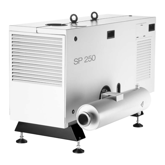
- Page 1 SCREWLINE SP 250 Dry Compressing Screw Vacuum Pump Operating Instructions GA02412_002_C0 115 001 115 003 ATEX 3i 115 006...
-
Page 2: Table Of Contents
Connections at the Intake Side 3.3.2 Connections at the Delivery Side (Exhaust Electrical Connection 3.4.1 Motor Protection 3.4.2 Star/Delta Start-up Circuit 3.4.3 Soft Start 3.4.4 Mains Connection 3.4.5 Power Failure 3.4.6 Operation with a Frequency Converter (FC Operation) GA02412_002_C0 - 10/2016 - © Leybold... - Page 3 Checking and Cleaning the Gas Ballast Filter Replacing the Throttle in the Purge Gas Device Service at Leybold Maintenance Schedule Troubleshooting Waste Disposal EC Declaration of Conformity These Operating Instructions are the original instructions. GA02412_002_C0 - 10/2016 - © Leybold...
- Page 4 Operating Instructions and follow the information so as to ensure optimum and safe working right from the start. The Leybold SCREWLINE SP 250 have been designed for safe and efficient operation when used properly and in accordance with these Operating Instructions.
-
Page 5: Important Safety Information
Reactive or corrosive gases may cause health problems . When the pump has been used to pump reactive or corrosive gases before, introduce corresponding safety precautions before opening it, e.g. wear gloves, breathing protection or protection clothing GA02412_002_C0 - 10/2016 - © Leybold... - Page 6 Connect the pump so that it not will restart automatically after a mains power failure, once the power returns. Overhead load Transport the pump only at the two crane eyes or with a forklift secured on a suitable palette. GA02412_002_C0 - 10/2016 - © Leybold...
-
Page 7: Mechanical Hazards
The crane eyes of the screw pump must never be used to lift any pump combinations (Roots pump + backing pump). GA02412_002_C0 - 10/2016 - © Leybold... -
Page 8: Electrical Hazards
After having connected the motor and each time after having made changes to the wiring, check the direction of rotation. If the direction of rotation is wrong, the pressure can increase on the intake side. Moreover, the pump can suffer severe damage. GA02412_002_C0 - 10/2016 - © Leybold... -
Page 9: Thermal Hazards
After installation of the pump and after servicing work on the vacuum, a leak search will always be necessary. Please note the special information on the pump’s shaft seal given in the following. GA02412_002_C0 - 10/2016 - © Leybold... - Page 10 When pump- ing harmful gases, the operator must ensure that such a malfunction cannot occur, respectively that leaks at the pump will not be a hazard. GA02412_002_C0 - 10/2016 - © Leybold...
-
Page 11: Ignition Risk
Safety Information Leybold is not in a position to perform servicing (repairs) and waste disposal of radioactively contaminated pumps. Both needs to be ensured from the side of the user. When disposing the pump, used lubricants and used oil filters observe the applicable environment regulations. -
Page 12: Risk Of Pump Damage
For proper connection, a suitable motor protection switch must be used. Set this motor protection switch in agreement with the informa- tion provided on the motor nameplate. Connect the pump to the correct mains voltage and mains frequency. GA02412_002_C0 - 10/2016 - © Leybold... - Page 13 Pressures given in bar or mbar are absolute values. If exceptionally a gauge pressure is meant, a “g” is added (bar(g) = bar (gauge) = bar overpressure) GA02412_002_C0 - 10/2016 - © Leybold...
-
Page 14: Sp 250 Atex Category 3I (Inside) Vacuum Pump
Equipment marked with IIC is also suited for applications which require equipment belonging to explosion group IIA or IIB. Equipment without indication of the explosion group may be used in explo- sive atmospheres of explosion groups IIA, IIB and IIC. GA02412_002_C0 - 10/2016 - © Leybold... -
Page 15: Areas Of Application
(i.e. Zone 2). GA02412_002_C0 - 10/2016 - © Leybold... - Page 16 Two calculations for determining two limit temperatures must be performed: a) Limit temperature 1 = of the minimum ignition temperature b) Limit temperature 2 = minimum glow point temperature* less 75 K GA02412_002_C0 - 10/2016 - © Leybold...
- Page 17 Chapter 3.5 Oil Temperature. The pump must be installed such that oil sight glass and SP-Guard are easily visible and cannot be damaged. The oil level must be checked regularly. GA02412_002_C0 - 10/2016 - © Leybold...
-
Page 18: Safety Measures
These can be caused by the electric motor and the accessories supplied with the pump. Where the outside of the pump has been certified then motor and supplied accessories have the same classification. Follow the manufacturer’s information. GA02412_002_C0 - 10/2016 - © Leybold... - Page 19 In order to ensure that the defined level of safety is maintained, only accesso- ry parts and wearing parts from Leybold must be used. GA02412_002_C0 - 10/2016 - © Leybold...
-
Page 20: Description
The SP 250 is air-cooled, a radial fan supports the cooling effect for the hou- sing which is equipped liberally with cooling fins. Depending on requirements, the screw pumps may be combined with Roots pumps so as to attain higher pumping speeds at lower pressures. GA02412_002_C0 - 10/2016 - © Leybold... - Page 21 (fig. 1.2) so that the chamber volume is already reduced at low pressures (fig. 1.3c). In this way a power consumption can be attained which is comparable to that of rotary vane pumps. GA02412_002_C0 - 10/2016 - © Leybold...
- Page 22 Fig. 1.2 Compression principle and the direction of pumping action within a screw pump without inner compression with inner compression against with inner compression the face side of the pump along the rotor chamber (SCREWLINE) Fig. 1.3 pV diagrams of screw pumps GA02412_002_C0 - 10/2016 - © Leybold...
-
Page 23: Technical Data
Temperature sensor in the motor coil PTC 160 °C - 5 °C PTC 160 °C - 5 °C Operating mode S1 (continuous operation) S1 (continuous operation) Operating agents Cooling Approved type of oil: LVO 210 GA02412_002_C0 - 10/2016 - © Leybold... -
Page 24: Technical Data Of The Sp-Guard Monitoring System
Power rating during operation Power rating when being energised 80 W Type of protection IP 65 acc. to IEC 60259 Cable diameter 6-7 mm Electrical connector with Varistor Bürkert, type 8376 acc. to DIN 43650 Form A GA02412_002_C0 - 10/2016 - © Leybold... -
Page 25: Technical Data Of The Purge Gas Facility
Maximum power consumption 3.4 W Protection type IP 65 in accordance with IEC 60259 Cable diameter < 6.5 mm Purge gas pressure/system pressure to be set up 2.5 bar Purge gas volume flow 20 Std. l/min GA02412_002_C0 - 10/2016 - © Leybold... - Page 26 Fig. 1.4 Pumping speed curves > 500 68-75 1348 > 500 Deviating height dimensions for pumps on castors > 500 (Dimensions in mm) Serviceabstand > 900 Clearance for maintenance work Dimensional drawing Fig. 1.5 GA02412_002_C0 - 10/2016 - © Leybold...
-
Page 27: Supplied Equipment
For the purpose of shipping the pump, the pump has been affixed to a spe- cial pallet. Retain this pallet in case the pump needs to be returned. GA02412_002_C0 - 10/2016 - © Leybold... -
Page 28: Built-In Accessories
SP-Guard may then be reset to the monitoring mode using the reset key. The service technician has the option of reading the most recently saved measured values from the internal memory of the SP-Guard. This information will help to analyse the reasons for the specific failure. GA02412_002_C0 - 10/2016 - © Leybold... - Page 29 50 Hz/60 Hz ATEX 3i 115 006 with manually operated gas ballast, 50 Hz/60 Hz Purge gas for shaft seal, Purge 300301758 Purge-Vent- Vent Kit and 4 swivelling castors Kit SP250 and integrated adjustable feet GA02412_002_C0 - 10/2016 - © Leybold...
-
Page 30: Accessories
215 206 200 - 230 V AC 215 207 Stability of the pump when using Leybold accessories is ensured. If other accessories are fitted then the user himself will be respon sible for maintaining pump stability. 1) Only in connection with installed purge gas facility 2) 119 054V can only be used from Serial No. -
Page 31: Transport And Storing
When doing so note the risk of slipping and toppling. If required secure the pump. For transporting, the silencer must be disassem- bled as otherwise there is the risk of toppling. GA02412_002_C0 - 10/2016 - © Leybold... -
Page 32: Pumps With Castors
When shelving the pump for prolonged periods, drain out of the oil from the pump. Package in the pump air-tight in polyethylene foil. Storage conditions Temperature -20 °C to + 60 °C Storage site Maximum atmospheric humidity 95 %, non-condensing GA02412_002_C0 - 10/2016 - © Leybold... -
Page 33: Installation
Technical Data. In all other operating modes and with other equipment, higher values may be attained. Suitable hearing protection measures must be intro- duced. GA02412_002_C0 - 10/2016 - © Leybold... -
Page 34: Ambient Conditions
The pumps have been designed to pump air or inert gases in the pressure range between atmospheric pressure and the ultimate pressure of the pump. If other gases are to be pumped with this pump, please consult Leybold first. For Part Number 115 003... -
Page 35: Connection To The System
The materials for the connecting lines must be capable of sustaining the medium which is being pumped. The pipe connections shall be connected to the pump free of any mechanical tensions. GA02412_002_C0 - 10/2016 - © Leybold... -
Page 36: Connections At The Intake Side
Remove protection foil and desiccant from the discharge flange. CAUTION The pressure in the discharge line must not exceed 200 mbar are above the ambient pressure. The discharge line must not be blocked or constrict- GA02412_002_C0 - 10/2016 - © Leybold... -
Page 37: Electrical Connection
The number of operating hours of the pump is acquired through the SP-Guard. The local connection conditions will possibly necessitate means for the pur- pose of reducing the surge currents upon switching the pump on. GA02412_002_C0 - 10/2016 - © Leybold... -
Page 38: Star/Delta Start-Up Circuit
The line cross-section for the mains power supply needs to be calculated in consideration of the cable length and the available mains circuit breaker. Using a mains power supply line having a cross-section of at least 4 x 6 mm is recommended. GA02412_002_C0 - 10/2016 - © Leybold... - Page 39 I / A I / A Δ ΔΔ Δ ΔΔ Δ Δ ΔΔ ΔΔ U / V U / V Diagram 3.1.1 Characteristic of the motor protection switch for delta circuit (Symbol ∆ respectively ∆∆ ) GA02412_002_C0 - 10/2016 - © Leybold...
- Page 40 3~ / 210 V 60 Hz For continuous operation! For starting only! Temperature sensor integrated in the coil. Caution Do not apply voltages in excess of 2.5 V Fig. 3.4 Mains connection (connection diagrams in the junction box) GA02412_002_C0 - 10/2016 - © Leybold...
- Page 41 Observe the direction of rotation of the running down fan. The correct direc- tion of rotation is indicated by an arrow in the junction box. In the case of a wrong connection, rewire. Close the housing again. GA02412_002_C0 - 10/2016 - © Leybold...
-
Page 42: Power Failure
In order to reduce the level of electromagnetic interference, shielded motor cables, shielded cable feedthroughs, motor filters and EMC-compliant ground connections between FC and pump will be necessary. Always also observe the information given in the Operating Instructions for the frequency converter. GA02412_002_C0 - 10/2016 - © Leybold... -
Page 43: Oil Temperature Sensor Pt 100
If the temperature of the oil deviates during normal loads and ambient con- NOTICE ditions from the process dependent standard values, the oil cooler should be checked to see if it has accumulated any dirt. GA02412_002_C0 - 10/2016 - © Leybold... - Page 44 24 V DC 2.5 W 2,5 W max. 3,4 W max. 3.4 W Oil tempera ture Öltemperatur- sensor sensor Oil level Ölstand- schalter switch Fig. 3.6 Block diagram for the screw pump with accessories GA02412_002_C0 - 10/2016 - © Leybold...
-
Page 45: Connecting The Sp-Guard
Switching output S1 (warning) red/blue Switching output S2 (error) white/green Switching output S3 (watchdog) brown/green Switching output S4 (pump on) yellow/brown 0 V (GND for PLC controller) Not connected Shield For connection, see fig. 3.8 GA02412_002_C0 - 10/2016 - © Leybold... - Page 46 1 V below the power supply voltage level and the low level is at approximately 1 V. The maximum current rating is 40 mA. The outputs are protected by means of semiconductor fuses. GA02412_002_C0 - 10/2016 - © Leybold...
- Page 47 Parameter Default settings Unit Description SP 250 digits Warning limit, vibrations digits Failure limit, vibrations 0,2 s Hysteresis, vibration meas. °C Warning limit, oil temperature °C Failure limit, oil temperature digits “Pump on” threshold GA02412_002_C0 - 10/2016 - © Leybold...
-
Page 48: Retrofitting The Manual Gas Ballast With A 24 V Dc Valve
The non-return valve has been glued in ensuring a tight seal. Unscrew the union nuts (30 mm spanner) and remove the manual gas ballast actuator. Reassemble the entire unit with the solenoid actuator. GA02412_002_C0 - 10/2016 - © Leybold... -
Page 49: Connecting The Electro-Pneumatic Gas Ballast Valve
• Push the flat gasket onto the connector pins Compression ring • Insert the connector socket up to the stop Sealing ring • Secure with cylinder head screw M 3 x 30 Collet Union nut Fig. 3.12 Fitting the connector GA02412_002_C0 - 10/2016 - © Leybold... -
Page 50: Connecting The Purge Gas Valve
Fig. 3.14 Connecting the connector at the purge gas valve Pressure connection for purge gas - G 1/8 inside thread or 6 mm plug-in connector. Unscrew the closure screw with the hexagon socket screw key Fig. 3.15 Connecting the purge gas GA02412_002_C0 - 10/2016 - © Leybold... -
Page 51: Operation
When doing so make sure that all aids used are clean so as to avoid con- taminating the oil. Use only lubricating oil which has been approved by Leybold. The gear oil should be filled in at room temperature. At lower temperatures, the oil is thicker so that there then is the risk of overfilling gear chamber with oil. - Page 52 Minimum mark at the oil sight glass Float ■ during standstill Minimum mark at the oil sight glass ■ during operation Oil drain plug Fig. 4.2 Oil level at the oil sight glass after the SP 250 GA02412_002_C0 - 10/2016 - © Leybold...
-
Page 53: Switching The Pump On
The gear housing is vented in the vicinity of fan wheel through two channels on the side opposite the exhaust. By design, small amounts of gear oil may escape through this vent. This will not adversely affect operation of the pump. GA02412_002_C0 - 10/2016 - © Leybold... -
Page 54: Operation
Press the pushbutton - long (3 seconds), and then short twice. A confirmation of the resetting pro- cess will be indicated on the display for approximately 5 seconds. GA02412_002_C0 - 10/2016 - © Leybold... -
Page 55: Gas Ballast Operation
A 90° turn of the knob will suffice for completely actuating the gas ballast valve, the gas ballast valve is either open or closed, see fig. on top. Electro-pneumatic gas ballast valve See Fig. 3.11 to 3.12. The valve is normally closed. GA02412_002_C0 - 10/2016 - © Leybold... -
Page 56: Purge Gas Operation
An error message will be displayed (and must be acknowledged), if the purge gas will be turned off prior to the SP Guard or turned on after the SP Guard. GA02412_002_C0 - 10/2016 - © Leybold... -
Page 57: Regular Checks
If much condensate is col- lected, the condensate separator will have to be checked regularly. GA02412_002_C0 - 10/2016 - © Leybold... -
Page 58: Switching Off/Shutting Down
Section 2 “Storing”. For this please contact Leybold for advice. Depending on the pump version switch off power supply for the SP-Guard ■... -
Page 59: Maintenance
All work within the pump should be left to suitably trained staff. In this con- text we would like to inform you about practical seminars offered by Leybold in which maintenance, repair and testing of the SP 250 are cov- ered by qualified instructors. Improperly performed maintenance or repair work will void the CE and ATEX conformity and void any warranty claims. -
Page 60: Checking The Oil Level
Place a sufficiently large collecting vessel (about 20 litres) under the pump. When disposing of the waste oil observe the applicable environment pro- tection regulations. Use only lubricants approved by Leybold. NOTICE To change the oil, the cover section on the discharge side needs to be disas- sembled, see fig. - Page 61 Pull the filter insert out. Push the new filter insert on until it positively engages. Replace the O-ring of the filter housing. Screw the filter housing on up to the stop and tighten. GA02412_002_C0 - 10/2016 - © Leybold...
-
Page 62: Cleaning The Oil Cooler
A dirty cooler may cause increased oil and pump temperatures and impair operation and reduce the service life of the pump. The oil cooler can be cleaned with an industrial vacuum cleaner after having removed one cover section. GA02412_002_C0 - 10/2016 - © Leybold... -
Page 63: Draining Out Condensate
Cleaning the Dust Filter in the Intake Line (optional) The dust filters which are installed upstream of the pump need to be checked regularly for contamination and cleaned as required. GA02412_002_C0 - 10/2016 - © Leybold... -
Page 64: Checking And Cleaning The Gas Ballast Filter
Unscrew the throttle with a 14 mm spanner. Connect the new throttle to the hose line. Insert the hose right up to the stop. GA02412_002_C0 - 10/2016 - © Leybold... - Page 65 Screw the throttle into the gear housing. Again insert the hose line into the throttle right up to the stop. Fit the pump cover again. Fig. 5.7 Set up the pressure at the supply unit GA02412_002_C0 - 10/2016 - © Leybold...
-
Page 66: Service At Leybold
Maintenance Service at Leybold If you send a pump to Leybold indicate whether the pump is free of sub- stances damaging to health or whether it is contaminated. If it is contaminated also indicate the nature of the hazard. To do so, you must use a preprinted form which we shall send to you upon request. -
Page 67: Maintenance Schedule
Ruvac adapter (replace (elastic parts) elastic parts only if defec- tive) Purge gasket, function test, after or 2.5 years Operator, on site EK 110000834 See Operating Instructions replace purge gas connec- purge gas kit tion GA02412_002_C0 - 10/2016 - © Leybold... -
Page 68: Troubleshooting
Display is dark Ambient temperature is too high. Let the SP-GUARD cool down and keep the Operator and difficult to ambient temperature below 40 °C. read. GA02412_002_C0 - 10/2016 - © Leybold... - Page 69 Fit a valve to shut off the intake port. the presence of (automatically upon pump standstill). a vacuum the pressure in the Valve at the intake port is not closed. Close the valve at the intake port. system increases too rapidly. GA02412_002_C0 - 10/2016 - © Leybold...
- Page 70 No need for action. junction box. Purge gas Valve has not switched. Check valve, if required connect correctly. Electrician gauge does not Purge gas supply has failed. Ensure a proper purge gas supply. indi cate any pressure. GA02412_002_C0 - 10/2016 - © Leybold...
-
Page 71: Waste Disposal
Waste oil from vacuum pumps must not be mixed with other substances or materials. Waste oil from vacuum pumps (Leybold oils which are based on mineral oils) which are subject to normal wear and which are contaminated due to the influence of oxygen in the air, high temperatures or mechanical wear must be disposed of through the locally available waste oil disposal system. -
Page 72: Ec Declaration Of Conformity
EC Declaration of Conformity GA02412_002_C0 - 10/2016 - © Leybold... - Page 73 GA02412_002_C0 - 10/2016 - © Leybold...
- Page 74 Notes GA02412_002_C0 - 10/2016 - © Leybold...
- Page 75 Person to contact: Calibration: Factory-calibr. Phone : Fax: Quality test certificate DIN 55350-18-4.2.1 End user: A. Description of the Leybold product: Failure description: Material description : Catalog number: Additional parts: Serial number: Application-Tool: Type of oil (ForeVacuum-Pumps) : Application- Process: B.
- Page 76 Sales and Service Germany Great Britain America Leybold Japan Co., Ltd. Tsukuba Technical Service Center Leybold UK LTD. 1959, Kami-yokoba Leybold GmbH Tsukuba-shi, Ibaraki-shi 305-0854 Unit 9 Sales, Service, Support Center (3SC) Japan Silverglade Business Park Bonner Strasse 498 Leybold USA Inc.
Need help?
Do you have a question about the ScrewLine SP250 and is the answer not in the manual?
Questions and answers