
Related Manuals for Schmalz SBPG


Summary of Contents for Schmalz SBPG
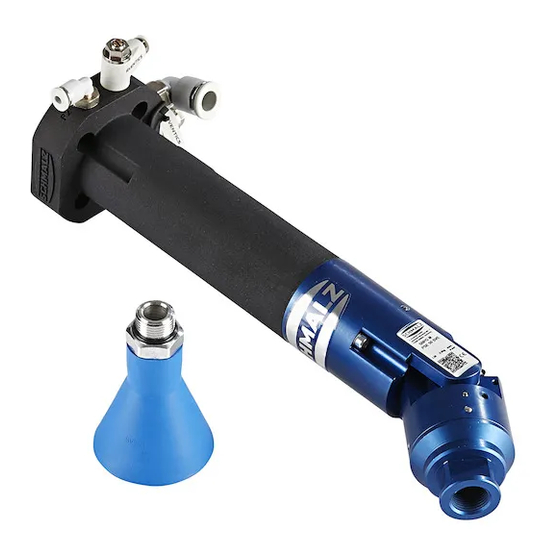
- Page 1 Gripping System SBPG Assembly Instructions WWW.SCHMALZ.COM EN-US · 30.30.01.02459 · 00 · 08/20...
- Page 2 Published by © J. Schmalz GmbH, 08/20 This document is protected by copyright. J. Schmalz GmbH retains the rights established thereby. Repro- duction of the contents, in full or in part, is only permitted within the limits of the legal provisions of copyright law. Any modifications to or abridgments of the document are prohibited without explicit writ- ten agreement from J. Schmalz GmbH.
-
Page 3: Table Of Contents
2.9 Country-Specific Regulations for the Operating Company .............. 9 3 Product Description ............................ 10 3.1 General Description of the Gripper..................... 10 3.2 Variants and Type Key ......................... 10 3.3 SBPG X PSE ............................ 11 3.4 SBPG X.............................. 12 3.5 SBPG M PSE ............................ 13 3.6 SBPG M.............................. 14 3.7 Quick-change function......................... - Page 4 Contents 8 Operation .............................. 24 8.1 Preparations............................ 24 9 Troubleshooting............................ 25 9.1 Safety .............................. 25 9.2 Faults, Causes, Solutions ........................ 25 10 Maintenance.............................. 27 10.1 Safety .............................. 27 10.2 Maintenance Schedule......................... 27 10.3 Cleaning the Gripper.......................... 28 10.4 Removing the Ejector Module...................... 29 10.5 Disassembling the Vacuum Switch ......................
-
Page 5: Important Information
ð Failure to follow the instructions in these Assembly instructions may result in life-threatening in- juries! ð Schmalz is not liable for damage or malfunctions that result from failure to heed these instructions. If you still have questions after reading the technical documentation, contact Schmalz Service at: www.schmalz.com/services... -
Page 6: Warnings In This Document
4 Please specify all the information above when ordering replacement parts, making warranty claims or for any other inquiries. 1.7 Other Applicable Documents The following operating instructions must also be observed when setting up the gripper SBPG: • The operating instructions for the ejector nozzle SEP •... -
Page 7: Fundamental Safety Instructions
The maximum lift capacity must not be exceeded (> See ch. Technical Data). 2.2 Non-Intended Use Schmalz accepts no liability for damage caused by the use of the gripper for purposes other than those described under Intended Use. Use of the gripper for loads that are not specified in the order confirma- tion or that have different physical properties than those specified in the order confirmation shall be con- sidered non-intended use. -
Page 8: Environmental And Operating Conditions
Work on electrical equipment must be carried out only by qualified electrical specialists. • Installation, maintenance, and repairs must be carried out only by specialists from J. Schmalz GmbH or by persons who can prove that they have undergone appropriate training at Schmalz. The following target groups are addressed in these instructions: •... -
Page 9: Personal Protective Equipment
• Safety features must not be disabled under any circumstances. Schmalz assumes no liability for consequences of modifications over which it has no control. 2.8 Responsibility of the Integrator The integrator is obligated to perform a risk assessment for the environmental conditions at the installa- tion location. -
Page 10: Product Description
If you have any questions about the design, please contact the Schmalz service team at: www.schmalz.com/services 3.2 Variants and Type Key The bin picker SBPG is available in four basic variants. The version is indicated in the item designation. The item designation is composed as follows: Abbreviated... -
Page 11: Sbpg X Pse
Product Description 3.3 SBPG X PSE The vacuum generator is integrated into the gripper, and the vacuum is monitored by the integrated vac- uum switch. The swiveling unit allows parts to be approached in the optimum way. Main gripper body (with silencer) - Page 12 Product Description 3.4 SBPG X The vacuum generator is integrated into the gripper, and the vacuum is monitored by the integrated vac- uum switch. Main gripper body (with silencer) Function module Suction cup Connection “P2” Compressed air connection D=4 mm Optional blow-off or operation of com- pressed air grippers Connection “P1”...
-
Page 13: Sbpg M Pse
Product Description 3.5 SBPG M PSE The gripper is supplied by an external vacuum. The vacuum is monitored by the integrated vacuum switch. The swiveling unit allows parts to be approached in the optimum way. Main gripper body (without silencer) Swiveling unit Suction cup Connection “P2”... -
Page 14: Sbpg M
Product Description 3.6 SBPG M The gripper is supplied by an external vacuum. The vacuum is monitored by the integrated vacuum switch. Main gripper body (without silencer) Function module Suction cup Connection “P2” Compressed air connection D=4 mm Optional blow-off or operation of com- pressed air grippers Connection “P1”... -
Page 15: Quick-Change Function
Product Description 3.7 Quick-change function All gripper versions are delivered with a quick-change function. It allows different types of suction gripper to be changed quickly and without tools, and also allows for quick-change adapters with different vac- uum and compressed air connections (> See ch. Accessories). 1. - Page 16 • Another option for communication is the "Schmalz ControlRoom" control and service app. This per- mits not only read access, but also active reconfiguration of the parameters via NFC. The Schmalz ControlRoom app is available at the Google Play Store.
-
Page 17: Technical Data
At minimum, the external vacuum generator used must supply the specified suction flow rate (at the vacuum connection piece of the SBPG M) with a vacuum of -0.15 bar For an in-depth system design, we always recommend performing suction tests with the original work- piece. - Page 18 Technical Data Type D (GR) L1 (SE) B (SE) SBPG M PSE 50 SVE 135° SBPG M 50 SVE –– –– –– Suction cups of other types and with other heights are available upon request All specifications (apart from angles) are in mm 18 / 36 EN-US ·...
-
Page 19: Transport And Storage
1. Compare the entire delivery with the supplied delivery notes to make sure nothing is missing. 2. Damage caused by defective packaging or occurring in transit must be reported immediately to the carrier and J. Schmalz GmbH. 5.2 Reusing the Packaging The product is delivered in cardboard packaging. The packaging should be reused to safely transport the product at a later stage. -
Page 20: Installation
Installation 6 Installation 6.1 Installation Instructions CAUTION Improper installation or maintenance Personal injury or damage to property 4 Prior to installation and before maintenance work, the product must be disconnected from the power supply, depressurized (vented to the atmosphere) and secured against unauthorized restart. -
Page 21: Electrical Connection
Installation 6.3 Electrical Connection DANGER Electric shock from touching live components Serious injury or death! 4 Make sure that the electrical components are not live before installation, maintenance and troubleshooting. 4 Switch off the mains switch and secure against unauthorized restart. A vacuum switch is installed on all gripper types. -
Page 22: Start Of Operations
Start of Operations 7 Start of Operations 7.1 Personnel Qualification Unqualified personnel cannot recognize dangers and are therefore exposed to higher risks! 1. Only instruct qualified personnel to perform the tasks described in these operating instructions. 2. The product may only be operated by persons who have undergone appropriate training. 3. - Page 23 Start of Operations CAUTION Risk of crushing if the suction cup is abruptly attached to a workpiece 4 Do not place any body parts between the suction cup and the workpiece Handling process 1. Placement of the gripper on the workpiece –...
-
Page 24: Operation
Operation 8 Operation 8.1 Preparations 4 The product must be operated only by persons who have undergone appropriate training. To avoid injury, always use appropriate protective equipment that is suitable for the situation. The protec- tive equipment must meet the following standards: •... -
Page 25: Troubleshooting
Troubleshooting 9 Troubleshooting 9.1 Safety Maintenance work may only be carried out by qualified personnel. WARNING Risk of injury due to incorrect maintenance or troubleshooting 4 Check the proper functioning of the product, especially the safety features, after every maintenance or troubleshooting operation. CAUTION Improper installation or maintenance Personal injury or damage to property... - Page 26 Troubleshooting Fault Possible cause Solution works, but work- Workpiece is too heavy Workpiece is not suitable pieces are not Vacuum is too high Determine the maximum possible vac- picked up uum of the vacuum generator; check the system for leaks (hose connections, sealing, etc.);...
-
Page 27: Maintenance
10.2 Maintenance Schedule Schmalz stipulates the following checks and check intervals. The operator must comply with the legal regulations and safety regulations applicable at the location of use. These intervals apply to single-shift operation. For heavier use, such as multi-shift operation, the intervals must be shortened accordingly. -
Page 28: Cleaning The Gripper
Maintenance Maintenance task Daily Weekly Monthly Every six Yearly months Check the function of the swiveling unit and quick-change adapter (replace the “pre-assembled plate” articulated connector – see wear parts) (> See ch. Replacing Articulated Connectors) Check that all the connections are se- cure, e.g. -
Page 29: Removing The Ejector Module
Maintenance 10.4 Removing the Ejector Module 4 Loosen the 2 screws (2) and separate the main body (1) and function module/swiveling unit (3) from each other 4 Remove the ejector module from the function module/swiveling unit For further cleaning of the ejector module, refer to operating instructions 30.30.01.00600 (> See ch. Other Applicable Documents). -
Page 30: Disassembling The Vacuum Switch
Maintenance 10.5 Disassembling the Vacuum Switch 4 Loosen the 2 screws (2) and separate the main body (1) and function module/swiveling unit (3) from each other 4 Disconnect the connection cable from the vac- uum switch 4 Unscrew the vacuum switch 30 / 36 EN-US ·... -
Page 31: Disassembling And Cleaning The Silencer Inserts
Maintenance 10.6 Disassembling and Cleaning the Silencer Inserts 1. Unscrew the screws (1) on the gripper head 2. Remove the retaining plate (2) 3. Remove the damping elements (3, 4) The damping elements can be cleaned with a soft brush. 10.7 Replacing Articulated Connectors The movements of the swiveling unit may cause the articulated connector plate (part no. -
Page 32: Accessories, Spare Parts And Wearing Parts
VSL 4-2 PU source (pneum. swiveling unit/blow-off) Solenoid valve 10.05.01.00070 for controlling the vacuum (only SBPG M) EMV 10 24V-DC 3/2 NO Quick-change adapter 10.01.45.00008 with open compressed air and vacuum duct... - Page 33 Maintenance Designation Part no. Note Suction plate holder 10.01.45.00005 Holder for use as a “station” for the quick-change HTR-S UNI RA adapter with suction cup. An inductive sensor can be fitted on the sheet metal angle bracket (for monitoring the presence of the suction cup in the holder).
-
Page 34: Disposing Of The Product
Disposing of the Product 11 Disposing of the Product Recover the disassembled parts for recycling or reuse (provided no agreement on return or disposal has been made). 1. Dispose of the product properly after replacement or decommissioning. 2. Observe the country-specific guidelines and legal obligations for waste prevention and disposal. 34 / 36 EN-US ·... -
Page 35: Ec Conformity
EC Conformity 12 EC Conformity EC declaration of incorporation The manufacturer Schmalz confirms that the gripping system described in these assembly instructions ful- fills the following applicable EC directives: 2006/42/EC Machinery Directive 2011/65/EU RoHs Directive The product specified is solely intended for installation indoors in a complete system. Startup is prohibited until the end product has been declared to comply with the Directive 2006/42/EC.
Need help?
Do you have a question about the SBPG and is the answer not in the manual?
Questions and answers