
Related Manuals for Schmalz Basic Ejector SBPL


Summary of Contents for Schmalz Basic Ejector SBPL
- Page 1 Operating instructions Basic Ejector SBPL WWW.SCHMALZ.COM EN-US · 30.30.01.01005 · 06 · 08/24 Translation of the original operating instructions...
- Page 2 Published by © J. Schmalz GmbH, 08/24 This document is protected by copyright. J. Schmalz GmbH retains the rights established thereby. Repro- duction of the contents, in full or in part, is only permitted within the limits of the legal provisions of copyright law. Any modifications to or abridgments of the document are prohibited without explicit writ- ten agreement from J. Schmalz GmbH.
-
Page 3: Table Of Contents
Contents Contents 1 Important Information.......................... 4 Note on Using this Document...................... 4 The technical documentation is part of the product ................ 4 Type Plate............................. 4 Symbols.............................. 5 2 Fundamental Safety Instructions ...................... 6 Intended Use ............................ 6 Non-Intended Use.......................... 6 Personnel Qualifications........................ -
Page 4: Important Information
ð Failure to follow the instructions in these Operating instructions may result in injuries! ð Schmalz is not liable for damage or malfunctions that result from failure to heed these instructions. If you still have questions after reading the technical documentation, contact Schmalz Service at: www.schmalz.com/services... -
Page 5: Symbols
1 Important Information 1.4 Symbols This symbol indicates useful and important information. ü This symbol represents a prerequisite that must be met before an action is performed. 4 This symbol represents an action to be performed. ð This symbol represents the result of an action. Actions that consist of more than one step are numbered: 1. -
Page 6: Fundamental Safety Instructions
2.2 Non-Intended Use Schmalz does not accept any liability for any direct or indirect losses or damages that result from using the product. This applies, in particular, to any use of the product that is not in accordance with the in- tended purpose and to any use that is not described or mentioned in this documentation. -
Page 7: Warnings In This Document
2 Fundamental Safety Instructions 2.4 Warnings in This Document Warnings warn against hazards that may occur when handling the product. The signal word indicates the level of danger. Signal word Meaning Indicates a medium-risk hazard that could result in death or serious injury if WARNING not avoided. -
Page 8: Modifications To The Product
4 Do not look into vacuum openings such as suction cups, suction lines and hoses. 2.6 Modifications to the Product Schmalz assumes no liability for consequences of modifications over which it has no control: 1. The product must be operated only in its original condition as delivered. -
Page 9: Product Design
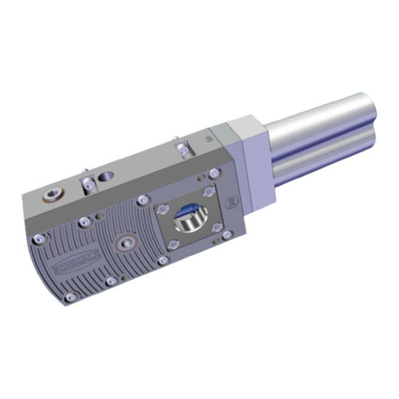
3 Product Design 3 Product Design 9/10 Exhaust air outlets M5 fastening screws (4x) Silencer Silencer holder Vacuum connection M4x16 fastening screws (2x for silencer holder) Blow-off connection/ventilation connec- M4x35 fastening screws (2x for silencer) tion, External blow-off with blow-off valve 2/2- NC* (vacuum-tight) M4 fastening screws (8x for enclosure Ejector module... -
Page 10: Technical Data
4 Technical Data 4 Technical Data 4.1 General parameters Working tempera- 0° C to +60° C ture Optimum operat- 4 bar to 5 bar ing pressure operating pres- 2 bar to 6 bar sure Operating Filtered and oiled or unoiled compressed air or neutral gases according to class medium on com- 7-4-4 of ISO 8573-1 pressed air side... - Page 11 4 Technical Data 4.4 Dimensions 167.5 285.3 73.5 ext. threa Type SBPL 25 HF/HV — — 3/8" female 3/4" int. 1/4" internal thread thread thread SBPL 25 HF/HV NPT — — NPT3/8 int. NPT3/4" fe- NPT1/4 int. thread male thread thread SBPL 50 HF/HV —...
- Page 12 4 Technical Data Type SBPL 125 HF/HV NPT NPT3/8 int. NPT1" int. NPT1/4 int. thread thread thread SBPL 150 HF/HV 3/8" female 1" female 1/4" internal thread thread thread SBPL 150 HF/HV NPT NPT3/8 int. NPT1" int. NPT1/4 int. thread thread thread All specifications are in mm...
-
Page 13: Checking The Delivery
1. Compare the entire delivery with the supplied delivery notes to make sure nothing is missing. 2. Damage caused by defective packaging or occurring in transit must be reported immediately to the carrier and J. Schmalz GmbH. EN-US · 30.30.01.01005 · 06 · 08/24... -
Page 14: Installation
6 Installation 6 Installation 6.1 Installation Instructions CAUTION Compressed air or vacuum in direct contact with the eye Severe eye injury! 4 Wear eye protection. 4 Do not look into compressed air openings. 4 Do not look into vacuum openings, e.g. suction cups. CAUTION Noise pollution due to incorrect installation of the pressure and vacuum con- nections... -
Page 15: Mounting
6 Installation 6.2 Mounting The illustrations shown below may deviate from the customer’s version because they serve as examples of different versions of the product. The product can be mounted in any position. 4 When installing the ejector, make sure that the area around the exhaust air opening (1) remains unobstructed to ensure the unim- peded discharge of the escaping air. -
Page 16: Pneumatic Connection
6 Installation 6.3 Pneumatic Connection 6.3.1 Instructions for the Pneumatic Connection 1. Ensure that you make all connections correctly and never close them off – danger of bursting! 2. To ensure problem-free operation and a long service life for the product, only use adequately main- tained compressed air. - Page 17 6 Installation 6.3.2 Connecting the Compressed Air and Vacuum Compressed air connector (marking 1) Blow-off connection Vacuum connection (marking 2) — — The compressed air connection is marked with the number 1 on the product. 4 Connect the compressed air hose. Maximum tightening torque = 10 Nm The vacuum connection is marked with the number 2 on the product.
-
Page 18: Start Of Operations
7 Start of Operations 7 Start of Operations 7.1 General Preparations WARNING Extraction of hazardous media, liquids or bulk material Personal injury or damage to property! 4 Do not extract harmful media such as dust, oil mists, vapors, aerosols etc. 4 Do not extract aggressive gases or media such as acids, acid fumes, bases, biocides, dis- infectants or detergents. -
Page 19: Warranty
8 Warranty 8 Warranty This system is guaranteed in accordance with our general terms of trade and delivery. The same applies to spare parts, provided that these are original parts supplied by us. We are not liable for any damage resulting from the use of non-original spare parts or accessories. The exclusive use of original spare parts is a prerequisite for the proper functioning of the ejector and for the validity of the warranty. -
Page 20: Maintenance
9 Maintenance 9 Maintenance 9.1 Safety Instructions Maintenance work may only be carried out by qualified personnel. 4 Create atmospheric pressure in the ejector’s compressed air circuit before working on the system! WARNING Failure to follow the instructions in these Operating instructions may result in injuries! 4 Read the Operating instructions carefully and observe the contents. - Page 21 9 Maintenance 2. Pull the ejector module (4) out of the bore- hole. Opening and cleaning the ejector module 1. Turn the nozzle fitting (1.2) relative to the main body (1.1) to the “unlocked” position. 2. Pull the nozzle fitting (1.2) out of the main body (1.1), pulling only in the axial direction.
- Page 22 9 Maintenance 5. Grease the O-rings slightly before mounting the ejector module. Assembling a new or cleaned ejector module 1. Lightly grease the ejector module O-rings (4) before mounting. 2. Ensure that the ejector module (4) is in the correct position and push it into the opening until it stops, with the suction openings of the ejector module (4) as shown.
-
Page 23: Replacing The Silencer
9 Maintenance 9.4 Replacing the Silencer Heavy infiltration of dust, oil, etc. may contaminate the silencer and reduce the suction capacity. Cleaning the silencer is not recommended due to the capillary effect of the porous material. If the suction capacity decreases, replace the silencer: ü... -
Page 24: Spare And Wearing Parts
10 Spare and Wearing Parts 10 Spare and Wearing Parts The product must be maintained only by qualified mechanics. Personnel must have read and understood the operating instructions. Designation Type Part no. Silencer SD 102x71x33 SBPL/SCPL 10.02.01.01585 Ejector module HF SEP HF 3 13 22 10.02.01.01996 Ejector module HV SEP HV 3 16 22... -
Page 25: Accessories
11 Accessories 11 Accessories Depending on the output module, the items listed in the following table are required for an upgrade. The installation information required for the conversion is stored with the relevant retrofit kit at www.schmalz.de. Upgrade Retrofitting kit Ejector... -
Page 26: Converting The Vacuum Connection To A Hose Sleeve
11 Accessories 11.1 Converting the Vacuum Connection to a Hose Sleeve The vacuum connection can be converted to a connection using a hose sleeve. For the corresponding sizes, the part numbers of the appropriate hose sleeves are listed in the accessories. The illustrations shown below may deviate from the customer’s version because they serve as examples of different versions of the product. -
Page 27: Decommissioning And Disposal
12 Decommissioning and Disposal 12 Decommissioning and Disposal 12.1 Disposing of the Product The components may only be prepared for disposal by qualified specialists. 1. Dispose of the product properly after replacement or decommissioning. 2. Observe the country-specific guidelines and legal obligations for waste prevention and disposal. 12.2 Materials Used The table below shows the materials used: Component... -
Page 28: Handling Systems
At Your Service Worldwide Vacuum automation Handling systems WWW.SCHMALZ.COM/AUTOMATION WWW.SCHMALZ.COM/EN-US/VACUUM-LIFTERS- AND-CRANE-SYSTEMS J. Schmalz GmbH Johannes-Schmalz-Str. 1 72293 Glatten, Germany T: +49 (0) 7443 2403-0 schmalz@schmalz.de WWW.SCHMALZ.COM...
Need help?
Do you have a question about the Basic Ejector SBPL and is the answer not in the manual?
Questions and answers