THORLABS PM100USB Operation Manual
Optical power meter
Hide thumbs
Also See for PM100USB:
- Operation manual (31 pages) ,
- Quick reference (4 pages) ,
- Operation manuals (99 pages)
Table of Contents
Advertisement
Quick Links
Advertisement
Table of Contents

Related Manuals for THORLABS PM100USB


Summary of Contents for THORLABS PM100USB
- Page 1 Optical Power Meter PM100USB Operation Manual 2020...
- Page 2 Version: Date: 13-Mar-2020 Copyright © 2020 Thorlabs...
-
Page 3: Table Of Contents
Contents Foreword 1 General Information 2 First Steps 2.1 Parts List 3 Operating Instruction 3.1 Operating Elements 3.2 Connecting a Power Sensor 4 Software 4.1 Requirements 5 Sensor Dependent Functions 5.1 Photodiode Sensors 5.1.1 Wavelength Setting 5.1.2 Bandwidth Setting (Signal Filtering) 5.1.3 Custom Photodiodes 5.2 Thermal Power Sensors... - Page 4 9.2 Pin Assignment of the Sensor Connector 9.3 Tutorial 9.3.1 Definitions and Explanations 9.3.1.1 Power Meter Specifications 9.3.1.2 Sensor Specifications 9.3.2 Calculations 9.4 Safety 9.5 Certifications and Compliances 9.6 Warranty 9.7 Copyright and Exclusion of Liability 9.8 Thorlabs Worldwide Contacts and WEEE policy...
-
Page 5: Foreword
Paragraphs preceded by this symbol explain hazards that could damage the instrument and the connected equipment or may cause loss of data. Note This manual also contains "NOTES" and "HINTS" written in this form. Please read this advice carefully! © 2020 Thorlabs... -
Page 6: General Information
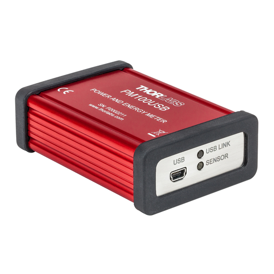
PM100USB 1 General Information The PM100USB Optical Power and Energy Meter measures the optical power of laser light or other monochromatic or near monochromatic light, detected by an appropriate sensor and is compatible with all Thorlabs “C-Series” Photodiodes, Thermal Sensors, Pyroelectrics Energy Sensors, and respective custom sensors. -
Page 7: First Steps
Inspect the shipping container for damage. If the shipping container seems to be damaged, keep it until you have inspected the contents for completeness and tested the PM100USB mechanically and electrically. Verify that you have received the following items within the package: 2.1 Parts List... -
Page 8: Operating Instruction
DE-9 connector. Upon connection, this information is automatically sent to the PM100USB and to the steering device and software. The software will automatically rec- ognize the sensor. For help to choose the most appropriate sensor, please refer to the chapter... - Page 9 PC to have the software recognize the power meter with the new sensor. Note Older Thorlabs Sensors without a DE-9 connector The PM100USB will NOT automatically recognize sensors lacking a DE-9 connector, as for the case of the 'A' and 'B' series. Please contact Thorlabs for an upgrade of old sensors with DE-9 connectors.
-
Page 10: Software
Do not connect the PM100USB prior to software installation! Note The PM100USB can also be run using custom made software. For this, please refer to the chapter Write-Your-Own-Application (WYOA) in the software manual. Older software versions can still be used to run the PM100USB. Please refer to the... -
Page 11: Sensor Dependent Functions
Low. 5.1.3 Custom Photodiodes The following custom photodiodes can also be used with the PM100USB: · Thorlabs photodiodes that are not part of the C-Series and do not have a DE-9 connector · Photodiodes from other providers © 2020 Thorlabs... -
Page 12: Thermal Power Sensors
PM100USB Required Adaptations 1) Adapter Connector To connect a custom sensor to the PM100USB, an adapter needs to be used. To build the a- dapter, please refer to the pin-out of the DE-9 connector shown in the Appendix . A photodi- ode and an interlock must be connected to the sensor input. -
Page 13: Read-Out Acceleration
· Thermal sensors from other providers Required Adaptations 1) Adapter Connector To connect a custom sensor to the PM100USB, an adapter needs to be used. To build the a- dapter, please refer to the pin-out of the DE-9 connector shown in the Appendix . -
Page 14: Auto Range
5.3.5 Custom Pyroelectric Sensors The following custom pyroelectric sensors can also be used with the PM100USB: · Thorlabs pyroelectric sensors that are not part of the C-Series and do not have a DE-9 con- nector · Pyroelectric sensors from other providers... - Page 15 5 Sensor Dependent Functions Required Adaptations 1) Adapter Connector To connect a custom sensor to the PM100USB, an adapter needs to be used. To build the a- dapter, please refer to the pin-out of the DE-9 connector shown in the Appendix .
-
Page 16: Measurement Considerations
The main application area for thermal sensors is the measurement of high power levels from 100mW up. Thorlabs offers also a special thermally isolated thermal head with flat response and on power levels starting in the µW range. -
Page 17: Reducing Noise For High Accuracy Measurements
The bandwidth should be set to Low , when using photodiode sensors. · · The acceleration circuit should be switched off when using thermal sensors. Choose a suitable sensor: The detector noise is lowest with Si or InGaAs sensors. · © 2020 Thorlabs... -
Page 18: Power Measurement Of Pulsed Signals
· 6.3 Power Measurement of Pulsed Signals The PM100USB will read the average value of a pulsed signal if the following conditions apply: Photodiode Sensor A photodiode sensor can follow short pulses in the nano second range. To achieve this, it is im- portant that the pulse peak power is within the maximum power range of the sensor and that the power range in the software is set such that the peak power will not exceed this range. -
Page 19: Ambient And Stray Light
On the other hand, for measurements with high power fiber lasers a certain gap between fiber tip and detector surface has to be kept to decrease the power density. Thorlabs offers fiber adapters with the most common connectors that are verified with the S12xC series optical sensors and with most thermal sensors. -
Page 20: Computer Interface
The connection between PC and PM100USB is accomplished by a USB cable with a male type ‘A’ connector at the PC side and a type ‘Mini-B’ connector on the instrument side. - Page 21 CURRent[:DC]:RANGe {MINimum|MAXimum|<numeric_value>[A]} Instead of selecting a specific current range, you can substitute MIN to set the range to its min- imum value or MAX to set the range to its maximum value. © 2020 Thorlabs...
- Page 22 (like W,DBM). They can have a short form and a long form just like command keywords. You can mix upper- and lower-case letters. Query responses will always return the short form in all upper-case letters. The following command uses discrete parameters: POW:UNIT {W|DBM} © 2020 Thorlabs...
- Page 23 You can include the quote delimiter as part of the string by typing it twice without any charac- ters in between. The following command uses a string parameter: DIAG:CALString <quoted string> © 2020 Thorlabs...
-
Page 24: Ieee488.2 Common Commands
Reads the Service Request Enable Register *STB? Status byte query Reads the Status Byte Register Performs the unit’s self-test and returns the Self-test query *TST? result. Wait until all previous commands are ex- *WAI Wait-to-continue command ecuted © 2020 Thorlabs... -
Page 25: Command Reference
7.1.2.2 Command Reference *IDN? – identification query - read identification code The identification code includes the manufacturer, model code, serial number, and firmware re- vision levels and is sent in the following format: THORLABS,MMM,SSS,X.X.X Where: MMM is the model code SSS is the serial number X.X.X is the instrument firmware revision level... -
Page 26: Pm100Usb Specific Scpi Command Reference
See also SCPI Specification, Version 1999.0, May, 1999, http://www.scpiconsortium.org. All commands with a ’SCPI’ checkmark are described in the SCPI specification. All described commands work with the PM100D, PM100A, PM100USB and PM200 instruments (with some limitations due to the hardware capabilities). - Page 27 :PTRansition? Read the positive transition filter :NTRansition <value> Program the negative transition filter :NTRansition? Read the negative transition filter :ENABle <value> Program the enable register :ENABle? Read the enable register :PRESet Return status registers to default states. © 2020 Thorlabs...
- Page 28 Sets the operation wavelength in nm WAVelength {MINimum| MAXimum| <numeric_value>[nm]} Queries the operation wavelength WAVelength? [{MINimum| MAXimum}] POWer [:PDIOde] Sets the photodiode response value in A/W [:RESPonse] {MINimum| MAXimum|DEFault| <numeric_value>[A]} Queries the photodiode response value [:RESPonse]? [{MINimum|MAXimum| DEFault}] :THERmopile © 2020 Thorlabs...
- Page 29 Queries the energy range MAXimum}] REFerence {MINimum| Sets a delta reference value in J MAXimum|DEFault| <numeric_value>[J]} REFerence? [{MINimum| Queries the delta reference value MAXimum|DEFault}] Switches to delta mode STATe {OFF|0|ON|1} STATe? Queries the delta mode state FREQuency *) Range © 2020 Thorlabs...
- Page 30 Queries the delta mode state STATe? PEAKdetector *) [:THReshold] {MINimum| Sets the trigger level in % for the energy mode MAXimum|DEFault| <numeric_value> [:THReshold]? [{MINimum| Queries the trigger level setting MAXimum|DEFault} *) Commands for PM100D, PM100USB and PM200 only © 2020 Thorlabs...
- Page 31 :TAU {MINimum|MAXimum|DEFault| Queries thermopile accelerator auto mode <numeric_value>[s]} Sets thermopile time constant 0-63% in s :TAU? [{MINimum|MAXimum|DEFault}] Queries the thermopile time constant in s :ADAPter Sets default sensor adapter type [:TYPE] {PHOTodiode|THERmal|PYRo} [:TYPE]? Queries default sensor adapter type © 2020 Thorlabs...
- Page 32 :RESistance Performs a sensor presence resistance measurement :TEMPerature Performs a sensor temperature measurement FETCh? Read last measurement data (SCPI Vol.2 §3.2) READ? Start new measurement and read data (SCPI Vol.2 §3.3) CONFigure? Query the current measurement configuration. © 2020 Thorlabs...
-
Page 33: Maintenance And Service
8 Maintenance and Service 8 Maintenance and Service Protect the PM100USB from adverse weather conditions. The PM100USB is not water resist- ant. Attention To avoid damage to the instrument, do not expose it to spray, liquids or solvents! The unit does not need regular maintenance by the user. It does not contain any modules and/or components that could be repaired by the user himself. -
Page 34: Appendix
± 0.5 % f.s. (10 mV - 1 V range) ± 1.0 % f.s. (1 mV range) Input Bandwidth (Analog) DC - 10Hz, depending on sensor and settings Wavelength Correction Sensor depending; nm, (V/W) Beam Diameter Setting 1/e² © 2020 Thorlabs... - Page 35 80 % up to 31° C, decreasing to 50 % at 40° C Operation Altitude < 3000 m ) non-condensing All technical data are valid at 23 ± 5°C and 45 ± 15% rel. humidity (non condensing) © 2020 Thorlabs...
- Page 36 1 µV 1 mV 0.1 µV ± 1.0 % f.s. Voltage Input Pyroelectrical Sensors Voltage Range Display Resolution Measurement Accuracy 100 V 100 mV 10 V 10 mV ± 0.5 % f.s. 1 mV 0.1V 100 µV © 2020 Thorlabs...
-
Page 37: Pin Assignment Of The Sensor Connector
+5V (max. current 50mA from this pin) DGND (digital ground) n.c. Warning Pin 2 is uniquely used for the EEPROM Digital I/O (memory in Thorlabs sensor heads) and MUST NOT be used. Connecting this pin may cause malfunction of the PM100USB. © 2020 Thorlabs... -
Page 38: Tutorial
Current input (photodiode sensors): The resolution is specified as: 1 pA / responsivity value [A/W] Therefore, the PM100USB has a resolution of 1 pA at the lowest measurement range (50 nA). The responsivity of a photo diode sensor is wavelength dependent and thus the power resolution is wavelength dependent as well. -
Page 39: Sensor Specifications
9 Appendix Therefore, the PM100USB has a resolution of 1 µV at the lowest measurement range (1 mV). The power resolution depends on the used sensor. Voltage input (pyroelectric sensors): The resolution is specified as: 100 µV / responsivity value [V/J] Therefore, the PM100USB has a resolution of 100 µV at the lowest measurement range (200... - Page 40 · Max. Pulse Energy Density is an alternative specification to max. average power density, which must not be exceeded. For definition and calculation, please see section Calcula- tions · Max. Average Power must not be exceeded to avoid damages to the sensor as a con- sequence of overheating. © 2020 Thorlabs...
-
Page 41: Calculations
Energy: The measurement unit of energy is J (Joule) - 1J is the energy that is necessary to provide the power of 1 W during 1s. It can be calculated from the peak power of the pulse and the pulse duration: © 2020 Thorlabs... - Page 42 The average power density is the ratio of the average power of the light beam to the area illu- minated by this beam. Given parameters Formula (average power), (beam diameter) (pulse peak power), peak (repetition rate), (pulse duration), (beam diameter) (pulse energy), (repetition rate) (beam diameter) © 2020 Thorlabs...
- Page 43 (pulse energy), (pulse duration), (beam diameter) (average power), (repetition rate), (pulse duration), (beam diameter) Pulse Energy Density Given parameters Formula (pulse energy), (beam diameter) (pulse peak power), peak (pulse duration), (beam diameter) (average power), (repetition rate), (beam diameter) © 2020 Thorlabs...
-
Page 44: Safety
If necessary, ask for replacement packaging. Refer servicing to qualified personnel. Only with written consent from Thorlabs may changes to single components be made or com- ponents not supplied by Thorlabs be used. -
Page 45: Certifications And Compliances
9 Appendix 9.5 Certifications and Compliances © 2020 Thorlabs... -
Page 46: Warranty
Thorlabs warrants material and production of the PM100USB for a period of 24 months starting with the date of shipment. During this warranty period Thorlabs will see to defaults by repair or by exchange if these are entitled to warranty. -
Page 47: Thorlabs Worldwide Contacts And Weee Policy
Contact Thorlabs for more information. Waste treat- ment is your own responsibility. “End of life” units must be returned to Thorlabs or handed to a company specializing in waste recovery. Do not dispose of the unit in a litter bin or at a public waste disposal site. - Page 48 www.thorlabs.com...
Need help?
Do you have a question about the PM100USB and is the answer not in the manual?
Questions and answers