THORLABS PM100USB Operation Manual
Optical power meter
Hide thumbs
Also See for PM100USB:
- Operation manual (48 pages) ,
- Quick reference (4 pages) ,
- Operation manuals (99 pages)
Table of Contents
Advertisement
Quick Links
Advertisement
Table of Contents

Subscribe to Our Youtube Channel
Related Manuals for THORLABS PM100USB


Summary of Contents for THORLABS PM100USB
- Page 1 Optical Power Meter PM100USB Operation Manual 2017...
- Page 2 Version: Date: 10-Oct-2017 Copyright © 2017 Thorlabs...
-
Page 3: Table Of Contents
5.2 Pin Assignment of the Sensor Connector 5.3 Tutorial 5.3.1 Definitions and explanations 5.3.1.1 Console Specifications 5.3.1.2 Sensor Specifications 5.3.2 Calculations 5.4 Certifications and Compliances 5.5 Warranty 5.6 Copyright and Exclusion of Reliability 5.7 Thorlabs 'End of Life' Policy (WEEE) 5.8 Thorlabs Worldwide Contacts... -
Page 4: Foreword
Paragraphs preceeded by this symbol explain hazards that could damage the instrument and the connected equipment or may cause loss of data. Note This manual also contains "NOTES" and "HINTS" written in this form. Please read these advices carefully! © 2017 Thorlabs... -
Page 5: General Information
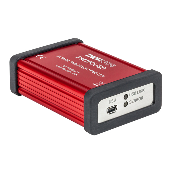
1 General Information 1 General Information The PM100USB Hand-held Optical Power and Energy Meter is designed to measure the optical power of laser light or other monochromatic or near mono- chromatic light sources. The space-saving, battery powered design and compatibility to all Thorlabs “C Series”... -
Page 6: Ordering Codes And Accessories
Thorlabs GmbH is not responsible for any radio television interference caused by modifications of this equipment or the substitution or attach- ment of connecting cables and equipment other than those specified by Thorlabs GmbH. -
Page 7: Parts List
Inspect the shipping container for damage. If the shipping container seems to be damaged, keep it until you have inspected the contents and you have inspected the PM100USB mechanically and electric- ally. Verify that you have received the following items within the package: 1. -
Page 8: Operating Instruction
Install software from the supplied data carrier (see section Software Installa- tion). · Connect a suitable sensor. · Connect the PM100USB to the PC using the supplied USB cable. · For detailed instructions, please see section Graphic User Interface. 3.1 Operating Elements Connector for power / energy sensor... -
Page 9: Connecting A Power Sensor
The PM100USB supports all Thorlabs ‘C-Series photodiode, energy and thermal sensors, that can be easily identified by their red connector housing, compared to older versions of Thorlabs power sensors. The console will not recognize sensors from the ‘A’ and ‘B’ series. Please contact... -
Page 10: Measurement Considerations
· With photodiode sensors the bandwidth should be set to “Low” setting; with thermal sensors the acceleration circuit should be shut off. · The detector noise is lowest with Si or InGaAs sensors. © 2017 Thorlabs... -
Page 11: Power Measurement Of Pulsed Signals
· The temperature should be stable over the time of the measurement. 4.3 Power Measurement of Pulsed Signals The PM100USB will read the average value of a pulsed signal if the following conditions apply: Thermal Sensor For a thermal sensor, pulse length, repetition rate and peak power are uncritical as long as the peak power is lower than the damage threshold of the sensor. -
Page 12: Temperature Effects On Thermal Sensors
The maximum ratings are given in the sensor specifications. The PM100USB can display the actual power or energy density for a known beam dia- meter. For high power or high energy beams a good efficiency can be reached by selecting a sensor with a detector size about 20% - 30% larger than the beam diameter. -
Page 13: Fiber Based Measurements
Thorlabs offers fiber adapters with the most common connectors that are verified with the S12xC series optical sensors and with most thermal sensors. - Page 14 The black coating is nearly linear flat over a wavelength range from 185nm to > 25µm; the ceramic coating is also suitable for this wavelength range, but is not linear over the entire wavelength range. © 2017 Thorlabs...
-
Page 15: Appendix
± 0.5 % f.s. (10 mV - 1 V range) ± 1.0 % f.s. (1 mV range) Input Bandwidth (Analog) DC - 10Hz, depending on sensor and settings Wavelength Correction Sensor depending; nm, (V/W) Beam Diameter Setting 1/e² © 2017 Thorlabs... - Page 16 USB cable A to Mini-B, 2 m USB Stick with - Application Software - Instrument Drivers - Thorlabs Instrument Communicator - Thorlabs DFU (Device Firmware Upgrade) Wizard General 0 to + 40 °C Operating Temperature Range Storage Temperature Range -40 to +70 °C Dimensions (W x H x D) 93.1 mm x 60.4 mm x 28.7 mm...
- Page 17 1 µV 1 mV 0.1 µV ± 1.0 % f.s. Voltage Input Pyroelectrical Sensors Voltage Range Display Resolution Measurement Accuracy 100 V 100 mV 10 V 10 mV ± 0.5 % f.s. 1 mV 0.1V 100 µV © 2017 Thorlabs...
-
Page 18: Pin Assignment Of The Sensor Connector
+5V (max. current 50mA from this pin) DGND (digital ground) n.c. Warning Pin 2 is uniquely used for the EEPROM Digital I/O (memory in Thorlabs sensor heads) and MUST NOT be used. Connecting this pin may cause malfunction of the PM100USB. © 2017 Thorlabs... -
Page 19: Tutorial
Calculations: Here common formulas are given - power, energy and densities can be calculated based on different given parameters. 5.3.1 Definitions and explanations In this section the key parameters of Thorlabs Power Meters and Sensors are commented. 5.3.1.1 Console Specifications ·... -
Page 20: Sensor Specifications
Voltage input (thermopile sensors): The resolution is specified to "1 µV / re- sponsivity value (V/W)". This means, that the PM100USB has in the lowest measurement range (1 mV) a resolution of 1 µV. The power resolution depends on the used sensor. - Page 21 · Max. Power Density is related to the pulse peak power and must not be ex- ceeded to avoid damages to the sensor. For definition and calculation, please see section Calculations. © 2017 Thorlabs...
- Page 22 Max. Pulse Energy Density is an alternative specification to max. average power density, which must not be exceeded. For definition and calculation, please see section Calculations. · Max. Average Power must not be exceeded to avoid damages to the sensor as a consequence of overheating. © 2017 Thorlabs...
-
Page 23: Calculations
Pulse diagram pulse duration pulse period pulse peak power Peak pulse average power Repetition rate is related to pulse period: Duty cycle is the ratio of pulse duration to pulse period: Pulse average power: Pulse peak power: © 2017 Thorlabs... - Page 24 The average power density is the ratio of the average power of the light beam to the area illuminated by this beam. Given parameters Formula (average power), (beam diameter) (pulse peak power), p eak (repetition rate), (pulse duration), (beam diameter) W (pulse energy), (repetition rate) (beam diameter) © 2017 Thorlabs...
- Page 25 (pulse duration), (beam diameter) (average power), (repetition rate), (pulse duration), (beam diameter) Pulse Energy Density Given parameters Formula W (pulse energy), (beam diameter) (pulse peak power), p eak (pulse duration), (beam diameter) (average power), (repetition rate), (beam diameter) © 2017 Thorlabs...
-
Page 26: Certifications And Compliances
PM100USB 5.4 Certifications and Compliances © 2017 Thorlabs... -
Page 27: Warranty
For warranty repairs or service the unit must be sent back to Thorlabs. The cus- tomer will carry the shipping costs to Thorlabs, in case of warranty repairs Thor- labs will carry the shipping costs back to the customer. -
Page 28: Copyright And Exclusion Of Reliability
PM100USB 5.6 Copyright and Exclusion of Reliability Thorlabs has taken every possible care in preparing this document. We however assume no li- ability for the content, completeness or quality of the information contained therein. The content of this document is regularly updated and adapted to reflect the current status of the hardware and/or software. -
Page 29: Thorlabs 'End Of Life' Policy (Weee)
Waste treatment on your own responsibility If you do not return an “end of life” unit to Thorlabs, you must hand it to a company specialized in waste recovery. Do not dispose of the unit in a litter bin or at a public waste disposal site. -
Page 30: Thorlabs Worldwide Contacts
Email: europe@thorlabs.com Email: scandinavia@thorlabs.com France Brazil Thorlabs SAS Thorlabs Vendas de Fotônicos Ltda. 109, rue des Côtes Rua Riachuelo, 171 78600 Maisons-Laffitte São Carlos, SP 13560-110 France Brazil Tel: +33-970 444 844 Tel: +55-16-3413 7062 Fax: +33-811 38 17 48 Fax: +55-16-3413 7064 www.thorlabs.com... - Page 31 www.thorlabs.com...
Need help?
Do you have a question about the PM100USB and is the answer not in the manual?
Questions and answers