Balluff BTL6-V11V-M A1-S115 Series Manual
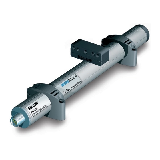
Micropulse at transducer in round profile housing
Hide thumbs
Also See for BTL6-V11V-M A1-S115 Series:
- Condensed manual (16 pages) ,
- User manual (18 pages)
Table of Contents
Advertisement
Available languages
Available languages
Quick Links
Advertisement
Chapters
Table of Contents

Related Manuals for Balluff BTL6-V11V-M A1-S115 Series


Summary of Contents for Balluff BTL6-V11V-M A1-S115 Series
- Page 1 BTL6-V11V-M _ _ _ _ -A1-S115 Betriebsanleitung deutsch...
-
Page 2: Table Of Contents
Einbau und Anschluss Wegaufnehmer einbauen Elektrischer Anschluss Schirmung und Kabelverlegung Inbetriebnahme System in Betrieb nehmen Hinweise zum Betrieb Geräteprofil Geräteprofil 6.1.1 Memory Address Space Mapping Positionsmessung mit dem Balluff BTL6‑V11V‑... Technische Daten Genauigkeit Umgebungsbedingungen Spannungsversorgung Eingänge/Ausgänge Maße, Gewichte Zubehör Positionsgeber Befestigungsklammern/‑schelle Steckverbinder Typenschlüssel... -
Page 3: Benutzerhinweise
BTL6-V11V-M _ _ _ _ -A1-S115 Micropulse AT-Wegaufnehmer im Profilgehäuse rund Benutzerhinweise Gültigkeit Mit dem CE-Zeichen bestätigen wir, dass unsere Produkte den Anforderungen der Diese Anleitung beschreibt Aufbau, Funktion und Einstell- EU-Richtlinie 2004/108/EG (EMV-Richt- möglichkeiten des Micropulse Wegaufnehmers BTL6 mit linie) entsprechen. -
Page 4: Sicherheit
Verwendung in eine Maschine oder Anlage von Gefahren. eingebaut. Die einwandfreie Funktion gemäß den Angaben in den technischen Daten wird nur mit original BALLUFF- Die verwendeten Warnhinweise enthalten verschiedene Zubehör zugesichert, die Verwendung anderer Komponen- Signalwörter und sind nach folgendem Schema aufgebaut: ten bewirkt Haftungsausschluss. -
Page 5: Aufbau Und Funktion
BTL6-V11V-M _ _ _ _ -A1-S115 Micropulse AT-Wegaufnehmer im Profilgehäuse rund Aufbau und Funktion Nennlänge Positionsgeber BTL6-A-3801-2 = Messbereich Befestigungsschelle Ø 5.5 BTL6-A-MF03-K-50 ~250 ~250 nicht im Lieferumfang enthalten nicht nutzbarer Bereich Bild 3-1: Wegaufnehmer BTL6..., Aufbau Aufbau Funktion Elektrischer Anschluss: Der elektrische Anschluss ist Im Wegaufnehmer BTL6 befindet sich der Wellenleiter, über eine Steckverbindung ausgeführt (siehe Typenschlüssel geschützt durch ein Aluminiumgehäuse. -
Page 6: Einbau Und Anschluss
2. Nut des Wegaufnehmers in Richtung Positionsgeber ausrichten! 3. Wegaufnehmer mit den Befestigungsschrauben auf Bild 4-3: Mindestabstand bei Verwendung mehrerer Positionsgeber dem Untergrund fixieren (Schrauben in den Klammern bzw. Schellen mit max. 4 Nm festziehen). 4. Postionsgeber (Zubehör) einbauen. www.balluff.com deutsch... -
Page 7: Elektrischer Anschluss
BTL6-V11V-M _ _ _ _ -A1-S115 Micropulse AT-Wegaufnehmer im Profilgehäuse rund Einbau und Anschluss (Fortsetzung) Elektrischer Anschluss Schirmung und Kabelverlegung Der Anschluss des BTL erfolgt über eine S115 Steckver- Definierte Erdung! bindung (siehe Zubehör auf Seite 14). Wegaufnehmer und Schaltschrank müssen auf dem gleichen Erdungspotenzial liegen. -
Page 8: Inbetriebnahme
3. Messwerte und einstellbare Parameter prüfen (insbesondere nach dem Austausch des Wegaufnehmers). Hinweise zum Betrieb – Funktion des Wegmesssystems und aller damit ver- bundenen Komponenten regelmäßig überprüfen. – Bei Funktionsstörungen das Wegmesssystem außer Betrieb nehmen. – Anlage gegen unbefugte Benutzung sichern. www.balluff.com deutsch... -
Page 9: Geräteprofil
BTL6-V11V-M _ _ _ _ -A1-S115 Micropulse AT-Wegaufnehmer im Profilgehäuse rund Geräteprofil Geräteprofil Der VARAN Bus ist ein industrielles Echtzeit-Bussystem, das auf der IEEE 802.3 100TX Standard Ethernet-Techno- logie basiert. 6.1.1 Memory Address Space Mapping Die Register sind folgenden Speicherplätzen zugeordnet: Adresse (hex) Beschreibung Größe (Byte) -
Page 10: Positionsmessung Mit Dem Balluff Btl6-V11V
BTL6-V11V-M _ _ _ _ -A1-S115 Micropulse AT-Wegaufnehmer im Profilgehäuse rund Geräteprofil (Fortsetzung) Positionsmessung mit dem Balluff BTL6‑V11V‑... INIT-FRAME T PLL_Sync_out Positionsgeber START/STOP Start Stop Stop N Start Bild 6-1: Grundsignale bei der Positionsmessung Bild 6-1 zeigt die Grundsignale der Positionsmessung. Der... - Page 11 1 kg/m onsgeber in der Mitte des Mess- Material Gehäuse Aluminium, eloxiert bereichs) Umgebungsbedingungen Einzelbestimmung nach Balluff-Werknorm Für : Der Wegaufnehmer muss extern über einen energiebegrenz- Betriebstemperatur 0 °C bis +70 °C ten Stromkreis gemäß UL 61010-1 oder eine Stromquelle begrenzter Lagertemperatur −40 °C bis +100 °C...
- Page 12 37.6 Ø 5.5 Ø 4.2 Bild 8-4: Befestigungsklammer BTL6-A-MF01-A-50 Material: Aluminium, eloxiert Bild 8-2: Einbaumaße Positionsgeber BTL6-A-3801-2 Gewicht: ca. 25 g BTL6‑A‑MF03‑K‑50 Gehäuse: Kunststoff Betriebstemperatur: −40 °C bis +85 °C Ø 5.5 Bild 8-5: Befestigungsschelle BTL6-A-MF03-K-50 Material: Kunststoff www.balluff.com deutsch...
- Page 13 BTL6-V11V-M _ _ _ _ -A1-S115 Micropulse AT-Wegaufnehmer im Profilgehäuse rund Zubehör (Fortsetzung) Steckverbinder Informationen zur Pinbelegung siehe Tabelle 4-2 auf Seite 8. BCC M488‑0000‑1A‑000‑43x834‑000 – Steckverbinder gewinkelt, frei konfektionierbar – M12, 8-polig Draufsicht auf Buchse Bild 8-6: Steckverbinder BCC M488-0000-1A-000-43x834-000 BCC M478‑0000‑1A‑000‑43x834‑000 –...
- Page 14 1 = 20 bis 28 V DC Anzahl Positionsgeber 1 = 1 Positionsgeber (Default) Ethernet-Schnittstellentyp V = VARAN Nennlänge (4-stellig) M0500 = metrische Angabe in mm, Nennlänge 500 mm Bauform A1 = Profilgehäuse, Durchmesser 30 mm Elektrischer Anschluss S115 Steckverbinder S115, M12, 8-polig www.balluff.com deutsch...
- Page 15 BTL6-V11V-M _ _ _ _ -A1-S115 Micropulse AT-Wegaufnehmer im Profilgehäuse rund Anhang 10.1 Umrechnung Längeneinheiten 1 mm = 0,03937008 inch 1 inch = 25,4 mm inch inch 0,03937008 25,4 0,07874016 50,8 76,2 0,11811024 101,6 0,15748031 0,19685039 152,4 0,23622047 177,8 0,27559055 203,2 0,31496063 228,6...
- Page 16 US Service Center CN Service Center Germany Germany China Balluff GmbH Balluff GmbH Balluff Inc. Balluff (Shanghai) trading Co., ltd. Schurwaldstrasse 9 Schurwaldstrasse 9 8125 Holton Drive Room 1006, Pujian Rd. 145. 73765 Neuhausen a.d.F. 73765 Neuhausen a.d.F. Florence, KY 41042 Shanghai, 200127, P.R.
- Page 17 BTL6-V11V-M _ _ _ _ -A1-S115 User's Guide english...
- Page 18 www.balluff.com...
- Page 19 Electrical connection Shielding and cable routing Startup Starting up the system Operating notes Device profile Device profile 6.1.1 Memory address space mapping Position sensing with the Balluff BTL6‑V11V‑... Technical data Accuracy Ambient conditions Supply voltage Inputs/outputs Dimensions, weights Accessories Magnet...
-
Page 20: Notes To The User
BTL6-V11V-M _ _ _ _ -A1-S115 Micropulse AT Transducer in round profile housing Notes to the user Validity The CE Mark verifies that our products meet the requirements of EU Directive This guide describes the construction, function and setup 2004/108/EC (EMC Directive). options for the BTL6 Micropulse Transducer with VARAN interface. -
Page 21: Safety
The warnings used here contain various signal words and specifications in the technical data is ensured only when are structured as follows: using original BALLUFF accessories. Use of any other SIGNAL WORD components will void the warranty. Hazard type and source... -
Page 22: Construction And Function
BTL6-V11V-M _ _ _ _ -A1-S115 Micropulse AT Transducer in round profile housing Construction and function Nominal length BTL6-A-3801-2 magnet = Measuring range Groove Bracket Ø 5.5 BTL6-A-MF03-K-50 ~250 ~250 Not included Unusable area Fig. 3-1: BTL6... transducer, construction Construction Function Electrical connection: The electrical connection is made The BTL6 transducer contains the waveguide which is... -
Page 23: Installation And Connection
2. Align transducer slot with magnet! 3. Attach transducer to the base using mounting screws (tighten screws in the clamps or brackets to a maximum of 4 Nm). Fig. 4-3: Minimum distance when using multiple magnets 4. Insert magnet (accessories). www.balluff.com english... -
Page 24: Electrical Connection
BTL6-V11V-M _ _ _ _ -A1-S115 Micropulse AT Transducer in round profile housing Installation and connection (continued) Electrical connection Shielding and cable routing The BTL is connected via a S115 connector (see Defined ground! Accessories on page 14). The transducer and the control cabinet must be at the same ground potential. -
Page 25: Startup
Operating notes – Check the function of the transducer and all associated components on a regular basis. – Take the position measuring system out of operation whenever there is a malfunction. – Secure the system against unauthorized use. www.balluff.com english... -
Page 26: Memory Address Space Mapping
BTL6-V11V-M _ _ _ _ -A1-S115 Micropulse AT Transducer in round profile housing Device profile Device profile The VARAN bus is an industrial real-time bus system based on the IEEE 802.3 100TX Standard Ethernet technology. 6.1.1 Memory address space mapping The registers are assigned to following memory spaces: Address (hex) Description... -
Page 27: Position Sensing With The Balluff Btl6-V11V
BTL6-V11V-M _ _ _ _ -A1-S115 Micropulse AT Transducer in round profile housing Device profile (continued) Position sensing with the Balluff BTL6‑V11V‑... INIT-FRAME T PLL_Sync_out Magnet START/STOP Start Stop Stop N Start Fig. 6-1: Basic signals for position sensing Fig. 6-1 displays the basic signals used for position sensing. - Page 28 Anodized aluminum magnet in the center of the stroke range) Individual specifications as per Balluff factory standard Ambient conditions : The transducer must be externally connected via a limited- energy circuit as defined in UL 61010-1, a low-power source as defined in Operating temperature 0 °C to +70 °C...
- Page 29 Fig. 8-4: BTL6-A-MF01-A-50 mounting clamp Material: Anodized aluminum Fig. 8-2: Installation dimensions of BTL6-A-3801-2 magnet Weight: Approx. 25 g BTL6‑A‑MF03‑K‑50 Housing: Plastic Operating temperature: −40 °C to +85 °C Ø 5.5 Fig. 8-5: BTL6-A-MF03-K-50 mounting bracket Material: Plastic www.balluff.com english...
- Page 30 BTL6-V11V-M _ _ _ _ -A1-S115 Micropulse AT Transducer in round profile housing Accessories (continued) Connectors For information on pin assignment, see Table 4-2 on page 8. BCC M488‑0000‑1A‑000‑43x834‑000 – Angled connector, freely configurable – M12, 8-pin Top view of socket Fig.
- Page 31 1 = 1 magnet (default) Ethernet interface type V = VARAN Nominal length (4-digit) M0500 = Metric specification in mm, nominal length 500 mm Construction A1 = Profile housing, diameter 30 mm Electrical connection S115 S115 connector, M12, 8-pin www.balluff.com english...
- Page 32 BTL6-V11V-M _ _ _ _ -A1-S115 Micropulse AT Transducer in round profile housing Appendix 10.1 Converting units of length 1 mm = 0.03937008 inches 1 inch = 25.4 mm inches inches 0.03937008 25.4 0.07874016 50.8 0.11811024 76.2 0.15748031 101.6 0.19685039 0.23622047 152.4 0.27559055...
- Page 33 US Service Center CN Service Center Germany Germany China Balluff GmbH Balluff GmbH Balluff Inc. Balluff (Shanghai) trading Co., ltd. Schurwaldstrasse 9 Schurwaldstrasse 9 8125 Holton Drive Room 1006, Pujian Rd. 145. 73765 Neuhausen a.d.F. 73765 Neuhausen a.d.F. Florence, KY 41042 Shanghai, 200127, P.R.
- Page 34 BTL6-V11V-M _ _ _ _ -A1-S115 Manual de instrucciones español...
- Page 35 www.balluff.com...
- Page 36 Puesta en servicio Puesta en servicio del sistema Indicaciones sobre el servicio Perfil del aparato Perfil del aparato 6.1.1 Memory Address Space Mapping Medición de posición con el Balluff BTL6‑V11V‑... Datos técnicos Precisión Condiciones ambientales Alimentación de tensión Entradas/salidas Medidas, pesos Accesorios Sensores de posición...
-
Page 37: Indicaciones Para El Usuario
BTL6-V11V-M _ _ _ _ -A1-S115 Transductor de desplazamiento AT Micropulse en carcasa perfilada redonda Indicaciones para el usuario Validez Con el marcado CE confirmamos que nuestros productos cumplen con los El presente manual describe la estructura, el requerimientos de la directiva de la funcionamiento y las posibilidades de ajuste del UE 2004/108/CE (directiva CEM). -
Page 38: Seguridad
óptimo según las indicaciones que figuran en los datos Las advertencias utilizadas contienen diferentes palabras técnicos solo se garantiza con accesorios originales de de señalización y se estructuran según el siguiente BALLUFF; el uso de otros componentes provoca la esquema: exoneración de responsabilidad. PALABRA DE SEÑALIZACIÓN... -
Page 39: Estructura Y Funcionamiento
BTL6-V11V-M _ _ _ _ -A1-S115 Transductor de desplazamiento AT Micropulse en carcasa perfilada redonda Estructura y funcionamiento Longitud nominal Sensor de posición BTL6-A-3801-2 = zona medible Ranura Abrazadera de fijación Ø 5.5 BTL6-A-MF03-K-50 ~250 ~250 No se incluye en el suministro Zona no aprovechable Fig. -
Page 40: Montaje Y Conexión
3. Fije el transductor de desplazamiento con los tornillos de fijación en la base (apriete los tornillos en las pinzas o abrazaderas con máx. 4 Nm). 4. Monte el sensor de posición (accesorio). www.balluff.com español... -
Page 41: Conexión Eléctrica
BTL6-V11V-M _ _ _ _ -A1-S115 Transductor de desplazamiento AT Micropulse en carcasa perfilada redonda Montaje y conexión (continuación) Conexión eléctrica Blindaje y tendido de cables El BTL se conecta mediante un conector S115 (véase Puesta a tierra definida Accesorios en la página 14). El transductor de desplazamiento y el armario eléctrico deben estar a idéntico potencial de Color... -
Page 42: Puesta En Servicio Del Sistema
Compruebe periódicamente el funcionamiento del sistema de medición de desplazamiento y todos los componentes relacionados. – Si se producen fallos de funcionamiento, ponga fuera de servicio el sistema de medición de desplazamiento. – Asegure la instalación contra cualquier uso no autorizado. www.balluff.com español... -
Page 43: Memory Address Space Mapping
BTL6-V11V-M _ _ _ _ -A1-S115 Transductor de desplazamiento AT Micropulse en carcasa perfilada redonda Perfil del aparato Perfil del aparato El bus VARAN es un sistema de bus industrial en tiempo real basado en la tecnología Ethernet estándar IEEE 802.3 100TX. - Page 44 BTL6-V11V-M _ _ _ _ -A1-S115 Transductor de desplazamiento AT Micropulse en carcasa perfilada redonda Perfil del aparato (continuación) Medición de posición con el Balluff BTL6‑V11V‑... INIT-FRAME T PLL_Sync_out sensor de posición START/STOP Start Stop Stop N Start Fig. 6-1: Señales básicas en la medición de posición...
- Page 45 ±0,04 % FS > 500 mm Coeficiente de temperatura ≤ 20 ppm/K Disposición individual según la norma de fábrica de Balluff (longitud nominal Para : el transductor de desplazamiento se debe conectar = 500 mm, sensor de externamente mediante un circuito eléctrico con limitación de energía de posición en el centro de la...
- Page 46 Fig. 8-2: Medidas de montaje del sensor de posición BTL6- A-3801-2 Peso: Aprox. 25 g BTL6‑A‑MF03‑K‑50 Carcasa: Material sintético Temperatura de servicio: De −40 °C a +85 °C Ø 5.5 Fig. 8-5: Abrazadera de fijación BTL6-A-MF03-K-50 Material: Material sintético www.balluff.com español...
- Page 47 BTL6-V11V-M _ _ _ _ -A1-S115 Transductor de desplazamiento AT Micropulse en carcasa perfilada redonda Accesorios (continuación) Conectores Para obtener información sobre la asignación de pines, véase la tabla 4-2 en la página 8. BCC M488‑0000‑1A‑000‑43x834‑000 – Conector acodado, libremente confeccionable –...
- Page 48 1 = 1 sensor de posición (ajuste predeterminado) Tipo de interface Ethernet V = VARAN Longitud nominal (4 cifras) M0500 = indicación métrica en mm, longitud nominal 500 mm Forma constructiva A1 = carcasa perfilada, diámetro 30 mm Conexión eléctrica S115 Conector S115, M12, 8 polos www.balluff.com español...
- Page 49 BTL6-V11V-M _ _ _ _ -A1-S115 Transductor de desplazamiento AT Micropulse en carcasa perfilada redonda Anexo 10.1 Conversión de unidades de longitud 1 mm = 0,03937008 pulgadas 1 pulgada = 25,4 mm pulgadas pulga‑ 0,03937008 25,4 0,07874016 50,8 0,11811024 76,2 0,15748031 101,6 0,19685039...
- Page 50 US Service Center CN Service Center Germany Germany China Balluff GmbH Balluff GmbH Balluff Inc. Balluff (Shanghai) trading Co., ltd. Schurwaldstrasse 9 Schurwaldstrasse 9 8125 Holton Drive Room 1006, Pujian Rd. 145. 73765 Neuhausen a.d.F. 73765 Neuhausen a.d.F. Florence, KY 41042 Shanghai, 200127, P.R.
- Page 51 BTL6-V11V-M _ _ _ _ -A1-S115 Notice d'utilisation français...
- Page 52 www.balluff.com...
- Page 53 Blindage et disposition des câbles Mise en service Mise en service du système Conseils d’utilisation Profil de l’appareil Profil de l’appareil 6.1.1 Memory Address Space Mapping Mesure des positions avec le BTL6‑V11V‑... de Balluff Caractéristiques techniques Précision Conditions ambiantes Alimentation électrique Entrées/Sorties Dimensions, poids...
- Page 54 BTL6-V11V-M _ _ _ _ -A1-S115 Capteur de déplacement Micropulse AT en boîtier rond profilé Informations destinées à l'utilisateur Validité Avec le symbole CE, nous certifions que nos produits répondent aux exigences Le présent manuel décrit la structure, le fonctionnement et de la directive européenne 2004/108/UE les possibilités de réglage du capteur de déplacement (directive CEM).
-
Page 55: Sécurité
MOT‑CLE accessoires d’origine de BALLUFF, l’utilisation d’autres composants entraîne la nullité de la garantie. Type et source de danger Conséquences en cas de non-respect du danger Tout démontage du capteur de déplacement ou toute... -
Page 56: Structure Et Fonction
BTL6-V11V-M _ _ _ _ -A1-S115 Capteur de déplacement Micropulse AT en boîtier rond profilé Structure et Fonction Longueur nominale Capteur de position BTL6-A-3801-2 = Plage de mesure Rainure Collier de fixation Ø 5.5 BTL6-A-MF03-K-50 ~250 ~250 ne fait pas partie des pièces livrées zone non exploitable Fig. -
Page 57: Montage Et Branchement
2. Aligner la rainure du capteur de déplacement en direction du capteur de position! Fig. 4-3 : Distance minimum entre plusieurs capteurs de position 3. Fixez le capteur de déplacement (vissage de max. 4 Nm dans les brides ou colliers). 4. Montez le capteur de position (accessoire). www.balluff.com français... -
Page 58: Branchement Électrique
BTL6-V11V-M _ _ _ _ -A1-S115 Capteur de déplacement Micropulse AT en boîtier rond profilé Montage et branchement (suite) Branchement électrique Blindage et disposition des câbles Le branchement du BTL se fait par un connecteur S115 Mise à la terre définie! (voir accessoire page 14). -
Page 59: Mise En Service
Conseils d’utilisation – Contrôlez régulièrement les fonctions du capteur de déplacement et de tous ses composants. – En cas de dysfonctionnement, mettez le système hors service. – Mettez le système à l’abri de toute utilisation non autorisée. www.balluff.com français... - Page 60 BTL6-V11V-M _ _ _ _ -A1-S115 Capteur de déplacement Micropulse AT en boîtier rond profilé Profil de l’appareil Profil de l’appareil Le bus VARAN est un système bus industriel en temps réel, qui est basé sur les standards IEEE 802.3 100TX de la technologie Ethernet.
-
Page 61: Mesure Des Positions Avec Le Btl6-V11V
BTL6-V11V-M _ _ _ _ -A1-S115 Capteur de déplacement Micropulse AT en boîtier rond profilé Profil de l’appareil (suite) Mesure des positions avec le BTL6‑V11V‑... de Balluff INIT-FRAME T PLL_Sync_out Capteur de position START/STOP Start Stop Stop N Start Fig. 6-1 : Signaux de base durant la mesure de position Le schéma 6-1 illustre les signaux de base de la mesure... - Page 62 Aluminium anodisé = 500 mm, capteur de position au milieu de la plage de mesure) Détermination individuelle selon la norme d’usine Balluff Pour : le capteur de déplacement doit être raccordé en externe Conditions ambiantes par un circuit à énergie limitée, ainsi que défini dans la norme UL 61010- 1, ou par une source basse tension selon UL 60950-1 ou encore par une...
- Page 63 Fig. 8-2 : Dimensions de montage du capteur de position BTL6-A-3801-2 Poids : env. 25 g BTL6‑A‑MF03‑K‑50 Boîtier : Plastique Température de service : −40 °C à +85 °C Ø 5.5 Fig. 8-5 : Collier de fixation BTL6-A-MF03-K-50 Matériau : Plastique www.balluff.com français...
- Page 64 BTL6-V11V-M _ _ _ _ -A1-S115 Capteur de déplacement Micropulse AT en boîtier rond profilé Accessoires (suite) Connecteurs Information sur l’affectation des broches, voir tableau 4-2, page 8. BCC M488‑0000‑1A‑000‑43x834‑000 – Connecteur coudé, à assembler – M12, 8 pôles Vue sur la douille de dessus Fig.
- Page 65 Type d’interface Ethernet V = VARAN Longueur nominale (4 chiffres) M0500 = donnée métrique en mm, longueur nominale 500 mm Forme de construction A1 = Boîtier profilé, diamètre 30 mm Branchement électrique S115 Connecteur S115, M12, 8 pôles www.balluff.com français...
- Page 66 BTL6-V11V-M _ _ _ _ -A1-S115 Capteur de déplacement Micropulse AT en boîtier rond profilé Annexe 10.1 Conversion unités de longueur 1 mm = 0,03937008 pouce 1 pouce = 25,4 mm pouce pouce 0,03937008 25,4 0,07874016 50,8 0,11811024 76,2 0,15748031 101,6 0,19685039 0,23622047...
- Page 67 US Service Center CN Service Center Germany Germany China Balluff GmbH Balluff GmbH Balluff Inc. Balluff (Shanghai) trading Co., ltd. Schurwaldstrasse 9 Schurwaldstrasse 9 8125 Holton Drive Room 1006, Pujian Rd. 145. 73765 Neuhausen a.d.F. 73765 Neuhausen a.d.F. Florence, KY 41042 Shanghai, 200127, P.R.
- Page 68 BTL6-V11V-M _ _ _ _ -A1-S115 Manuale d'uso italiano...
- Page 69 www.balluff.com...
- Page 70 Schermatura e posa dei cavi Messa in funzione Messa in funzione del sistema Avvertenze per il funzionamento Profilo del dispositivo Profilo del dispositivo 6.1.1 Memory Address Space Mapping Misurazione della posizione con Balluff BTL6‑V11V‑... Dati tecnici Precisione Condizioni ambientali Alimentazione elettrica Ingressi/uscite Dimensioni, pesi...
- Page 71 BTL6-V11V-M _ _ _ _ -A1-S115 Trasduttore di posizione Micropulse AT in corpo profilato circolare Avvertenze per l'utente Validità Il marchio CE è la conferma che i nostri prodotti sono conformi ai requisiti della Queste istruzioni descrivono la struttura, il funzionamento e Direttiva UE 2004/108/CE le possibilità...
- Page 72 è garantito soltanto con accessori originali schema seguente: BALLUFF, l’uso di altri componenti comporta l’esclusione PAROLA DI SEGNALAZIONE della responsabilità. Natura e fonte del pericolo L’apertura o l’uso improprio del trasduttore di posizione...
- Page 73 BTL6-V11V-M _ _ _ _ -A1-S115 Trasduttore di posizione Micropulse AT in corpo profilato circolare Struttura e funzione Lunghezza nominale Datore di posizione BTL6-A-3801-2 = campo di misura Scanalatura Fascetta di fissaggio Ø 5.5 BTL6-A-MF03-K-50 ~250 ~250 non compresa nella fornitura campo non utilizzabile Fig.
- Page 74 Distanza minima in caso di utilizzo di più datori di posizione direzione del datore di posizione! 3. Fissare il trasduttore di posizione sulla base con le viti di fissaggio (serrare le viti nelle staffe o nelle fascette con max. 4 Nm). 4. Montare il datore di posizione (accessorio). www.balluff.com italiano...
- Page 75 BTL6-V11V-M _ _ _ _ -A1-S115 Trasduttore di posizione Micropulse AT in corpo profilato circolare Montaggio e collegamento (continua) Collegamento elettrico Schermatura e posa dei cavi Il collegamento del BTL avviene tramite un connettore a Messa a terra definita! spina S115 (vedere Accessori a pagina 14). Il trasduttore di posizione e l'armadio elettrico devono trovarsi sullo stesso potenziale di terra.
- Page 76 Controllare periodicamente il funzionamento del sistema di misura della corsa e di tutti i componenti ad esso collegati. – In caso di anomalie di funzionamento disattivare il sistema di misura della corsa. – Proteggere l'impianto da un uso non autorizzato. www.balluff.com italiano...
- Page 77 BTL6-V11V-M _ _ _ _ -A1-S115 Trasduttore di posizione Micropulse AT in corpo profilato circolare Profilo del dispositivo Profilo del dispositivo Il bus VARAN è un sistema di bus industriale in tempo reale basato sulla tecnologia standard Ethernet IEEE 802.3 100TX. 6.1.1 Memory Address Space Mapping I registri sono assegnati alle seguenti posizioni di memoria: Indirizzo (hex)
- Page 78 BTL6-V11V-M _ _ _ _ -A1-S115 Trasduttore di posizione Micropulse AT in corpo profilato circolare Profilo del dispositivo (continua) Misurazione della posizione con Balluff BTL6‑V11V‑... INIT-FRAME T PLL_Sync_out datore di posizione START/STOP Start Stop Stop N Start Fig. 6-1: Segnali fondamentali per la misurazione della posizione La Figura 6-1 mostra i segnali fondamentali per la misurazione della posizione.
- Page 79 > 500 mm Coefficiente di temperatura ≤ 20 ppm/K (lunghezza nominale = 500 Rilevazione singola secondo la norma interna Balluff mm, datore di posizione al centro dell'intervallo di : Il trasduttore di posizione deve essere collegato misurazione) esternamente mediante un circuito elettrico ad energia limitata in base alla norma UL 61010-1 oppure mediante una fonte di energia a potenza...
- Page 80 Fig. 8-2: Dimensioni di ingombro datore di posizione BTL6- A-3801-2 Peso: circa 25 g BTL6‑A‑MF03‑K‑50 Corpo: materiale plastico Temperatura di esercizio: da −40 °C a +85 °C Ø 5.5 Fig. 8-5: Fascetta di fissaggio BTL6-A-MF03-K-50 Materiale: materiale plastico www.balluff.com italiano...
- Page 81 BTL6-V11V-M _ _ _ _ -A1-S115 Trasduttore di posizione Micropulse AT in corpo profilato circolare Accessori (continua) Connettori Per informazioni sulla piedinatura vedere la Tabella 4-2 a pagina 8. BCC M488‑0000‑1A‑000‑43x834‑000 – Connettore angolato, confezionabile liberamente – M12, a 8 poli Vista in pianta della presa Fig.
- Page 82 Tipo interfaccia Ethernet V = VARAN Lunghezza nominale (a 4 cifre) M0500 = indicazione metrica in mm, lunghezza nominale 500 mm Forma costruttiva A1 = corpo profilato, diametro 30 mm Collegamento elettrico S115 Connettore S115, M12, a 8 poli www.balluff.com italiano...
- Page 83 BTL6-V11V-M _ _ _ _ -A1-S115 Trasduttore di posizione Micropulse AT in corpo profilato circolare Appendice 10.1 Conversione delle unità di lunghezza 1 mm = 0,03937008 pollici 1 pollice = 25,4 mm pollice pollice 0,03937008 25,4 0,07874016 50,8 0,11811024 76,2 0,15748031 101,6 0,19685039...
Need help?
Do you have a question about the BTL6-V11V-M A1-S115 Series and is the answer not in the manual?
Questions and answers