Table of Contents
Advertisement
Quick Links
Advertisement
Table of Contents

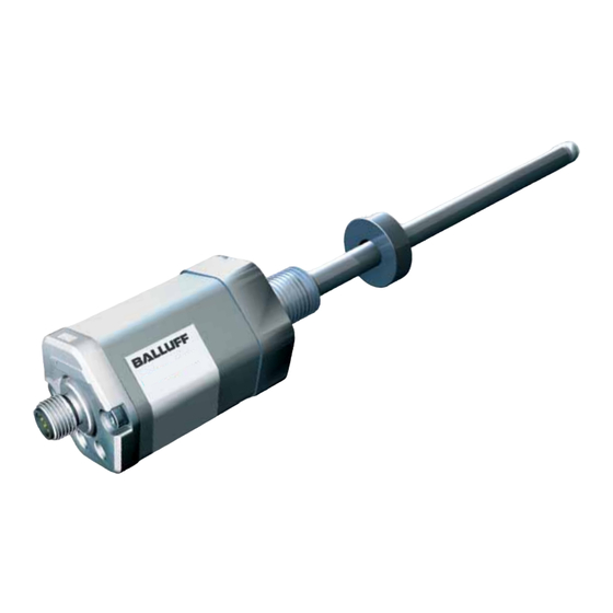
Summary of Contents for Balluff BTL6-V11V-M Series
- Page 1 BTL6-V11V-M _ _ _ _ -A/B/Y/Z(8)-S115 User's Guide english...
- Page 2 www.balluff.com...
-
Page 3: Table Of Contents
Electrical connection Shielding and cable routing Startup Starting up the system Operating notes Device profile Device profile 6.1.1 Memory address space mapping Position sensing with the Balluff BTL6‑V11V‑... Technical data Accuracy Ambient conditions Supply voltage Inputs/outputs Dimensions, weights Accessories Magnets... -
Page 4: Notes To The User
BTL6-V11V-M _ _ _ _ -A/B/Y/Z(8)-S115 Micropulse Transducer - Rod Style Notes to the user Validity The CE Mark verifies that our products meet the requirements of EU Directive This guide describes the construction, function and setup 2004/108/EC (EMC Directive). options for the BTL6 Micropulse Transducer with VARAN interface. -
Page 5: Safety
The warnings used here contain various signal words and specifications in the technical data is ensured only when are structured as follows: using original BALLUFF accessories. Use of any other SIGNAL WORD components will void the warranty. Hazard type and source... -
Page 6: Construction And Function
BTL6-V11V-M _ _ _ _ -A/B/Y/Z(8)-S115 Micropulse Transducer - Rod Style Construction and function Mounting surface Damping zone 1) B: 30-1 mm Z: 2"-0.04" Nominal length = Measuring range BTL6...S115 Magnet 2) Thread size 0.5 Ø 25 B: M18x1.5 Z: 3/4"-16UNF 12.8 Mounting surface A: 30-1 mm... -
Page 7: Installation And Connection
At least 13 mm Fig. 4-4: Mounting hole 3/4”-16UNF per SAE J475 O-ring 15.3x2.4 8 mm At least 11 mm Magnet: Various magnets are available for the BTL6 Tab. 4-1: Bore diameter if installed in a hydraulic cylinder transducer (see Accessories on page 14). www.balluff.com english... -
Page 8: Installing The Transducer
BTL6-V11V-M _ _ _ _ -A/B/Y/Z(8)-S115 Micropulse Transducer - Rod Style Installation and connection (continued) The slide element can be screwed on or bonded. Installing the transducer ► Secure the screws so they cannot be loosened or lost. ► Select a suitable adhesive. NOTICE! Slide surface Interference in function... -
Page 9: Electrical Connection
Unassigned leads can be connected to the GND on the controller side but not to the shield. Reference potential for supply voltage and EMC-GND. Tab. 4-2: Pin assignment of S115 connector Fig. 4-9: Pin assignment of S115 (view of connector pins of transducer), 8-pin M12 circular plug www.balluff.com english... -
Page 10: Startup
BTL6-V11V-M _ _ _ _ -A/B/Y/Z(8)-S115 Micropulse Transducer - Rod Style Startup Starting up the system DANGER Uncontrolled system movement When starting up, if the position measuring system is part of a closed loop system whose parameters have not yet been set, the system may perform uncontrolled movements. -
Page 11: Device Profile
– Stop overflow: This bit is set if the number of detected stops is more than the number of magnets entered in the Config register. – Reserved bits (bit 2, bit 3) in LSB are always 0. www.balluff.com english... -
Page 12: Position Sensing With The Balluff Btl6-V11V
BTL6-V11V-M _ _ _ _ -A/B/Y/Z(8)-S115 Micropulse Transducer - Rod Style Device profile (continued) Position sensing with the Balluff BTL6‑V11V‑... INIT-FRAME T PLL_Sync_out Magnet START/STOP Start Stop Stop N Start Fig. 6-1: Basic signals for position sensing Fig. 6-1 displays the basic signals used for position sensing. -
Page 13: Technical Data
Ambient conditions Nominal length 500 mm, magnet in the middle of the measuring range Operating temperature 0°C to +70°C Individual specifications as per Balluff factory standard : The transducer must be externally connected via a limited- Storage temperature −40°C to +100°C energy circuit as defined in UL 61010-1, a low-power source as defined in... -
Page 14: Accessories
BTL6-V11V-M _ _ _ _ -A/B/Y/Z(8)-S115 Micropulse Transducer - Rod Style Accessories BTL‑P‑1013‑4R, BTL‑P‑1013‑4S, BTL‑P‑1012‑4R, Accessories are not included in the scope of delivery and must be ordered separately. BTL‑P‑1014‑2R: Weight: Approx. 10 g Housing: Anodized aluminum Magnets BTL‑P‑1013‑4R Included in the scope of delivery for the BTL‑P‑1013‑4R, BTL‑P‑1013‑4S, BTL‑P‑1012‑4R: Spacer: 8 mm, material: polyoxymethylene... -
Page 15: Connectors
BCC M488‑0000‑1A‑000‑43x834‑000 – Angled connector, freely configurable – M12, 8-pin Top view of socket Fig. 8-3: Connector BCC M488-0000-1A-000-43x834-000 BCC M478‑0000‑1A‑000‑43x834‑000 – Straight connector, freely configurable – M12, 8-pin Top view of socket Fig. 8-4: Connector BCC M478-0000-1A-000-43x834-000 www.balluff.com english... -
Page 16: Type Code Breakdown
BTL6-V11V-M _ _ _ _ -A/B/Y/Z(8)-S115 Micropulse Transducer - Rod Style Type code breakdown BTL6 ‑ V 1 1 V ‑ M0500 ‑ B ‑ S115 Micropulse transducer Ethernet interface Supply voltage: 1 = 20 to 28 V DC Data protocol: 1 = 1 magnet (default) Ethernet interface type: V = VARAN Nominal length (4-digit):... -
Page 17: Appendix
Type 07112200054321 DE 0.27559055 Serial number 0.31496063 0.35433071 0.393700787 Tab. 10-1: Conversion table mm to inches 1 inch = 25.4 mm Fig. 10-1: BTL6 part label inches 25.4 50.8 76.2 101.6 152.4 177.8 203.2 228.6 Tab. 10-2: Conversion table inches to mm www.balluff.com english... - Page 18 US Service Center CN Service Center Germany Germany China Balluff GmbH Balluff GmbH Balluff Inc. Balluff (Shanghai) trading Co., ltd. Schurwaldstrasse 9 Schurwaldstrasse 9 8125 Holton Drive Room 1006, Pujian Rd. 145. 73765 Neuhausen a.d.F. 73765 Neuhausen a.d.F. Florence, KY 41042 Shanghai, 200127, P.R.


Need help?
Do you have a question about the BTL6-V11V-M Series and is the answer not in the manual?
Questions and answers