
Related Manuals for Rion VT-06


Summary of Contents for Rion VT-06
- Page 1 INSTRUCTION MANUAL VISCOTESTER VT-06 3-20-41 Higashimotomachi, Kokubunji, Tokyo 185-8533, Japan http://www.rion.co.jp/english/...
- Page 3 Organization of this manual This manual describes the features and operation principles of the Viscotester VT-06. The following pages contain important information on safety. Be sure to read this part. This manual contains the following sections. Outline Gives basic information on the features of the unit.
- Page 4 Measurement Describes how to perform the measurement. Applied part Describes rotor extension. Specifi cations Lists the technical specifi cations of the unit. * All company names and product names mentioned in this manual are trademarks or registered trademarks of their respective owners.
-
Page 5: For Safety
FOR SAFETY In this manual, important safety instructions are specially marked as shown below. To prevent the risk of injury to persons and severe damage to the unit or peripheral equipment, make sure that all instructions are fully understood and observed. Caution D isrega rd i ng i nst r uct ions printed here incurs the risk of... - Page 6 Precautions • The No. 1 rotor and No. 2 rotor are designed for making measurements using a JIS 300 mL beaker containing about 350 mL of sample fl uid. If another container is used, the viscosity resistance working on the rotor will be different, leading to deviations in the measurement result.
- Page 7 • The viscosity scale readings for the various rotor types overlap in part. For example, the following viscosity ranges can be measured with the following both rotors: 3 dPa•s to 13 dPa•s: No. 3 or No. 1 rotor 100 dPa•s to 150 dPa•s: No. 2 or No. 1 rotor However, depending on the properties of the sample fl uid and on mechan- ical calibration results, the obtained measurement values may be different when changing rotors.
- Page 8 • Keep the time for one measurement under 100 seconds. • Ambient conditions for operation of the unit are as follows: temperature range 5°C to 35°C, relative humidity 10% to 90%RH. • Because the drive section is not hermetically sealed, do not use the unit in environments with volatile gas or dust pollution.
- Page 9 • The rubber section of the rotor mounting shaft may drop out at the time of measurement. When you want to avoid the foreign material to a sample, remove the rubber section at the time of measurement. • Remove the batteries from the unit when it is not being used, to prevent the possibility of damage by leaking battery fl uid.
- Page 10 • Clean the unit only by wiping it with a soft, dry cloth or, when necessary, with a cloth lightly moistened with water. Do not use any solvents, cleaning alcohol or chemical cleaning agents. • The optional stand (VA-04) is useful to stabilize the viscotester during long-term or continuous measurements.
-
Page 11: Change In Viscosity Unit
Change in viscosity unit According to Japanese and international standard agreements, the viscosity unit is displayed in the Pascal-second (Pa•s). The relation between the Pa•s and Poise (P) is as follows. 1 dP•s = 1 P dPa•s: Decipascal-seconds Poise... -
Page 12: Table Of Contents
Contents FOR SAFETY ................iii Change in viscosity unit ..............ix Outline ....................1 Controls and functions ..............2 Confi guration ................2 Top view ..................3 Rear view ...................4 Bottom view ................5 Display ..................6 Operation key panel ..............7... - Page 13 Preparations ..................9 Power Supply ................9 Attaching the Rotor ..............14 Preparing the Sample Fluid ...........15 Measurement ................. 16 Applied part ..................20 Rotor extension ................20 Specifi cations ................21...
- Page 14 This product may cause interference if used in residential areas. Such use must be avoided unless the user takes special measures to reduce electromagnetic emissions to prevent interference to the reception of radio and television broadcasts. To conform to the EU requirement of the Directive on Waste Electrical and Electronic Equipment, the symbol mark on the right is shown on the instrument.
-
Page 15: Outline
Outline The Viscotester VT-06 is a compact, uni-cylinder rotational viscometer designed for easy use in the fi eld. When a rotor put into the sample liquid is rotated by fi xed speed, a viscous resistance is caused. Viscosity can be measured by detecting the viscous resistance (torque). -
Page 16: Controls And Functions
Controls and functions Confi guration Main unit No. 1 rotor No. 2 rotor No. 3 rotor IEC LR6 No. 3 cup (size AA) batteries AC adapter (option) Rotor extension... -
Page 17: Top View
Controls and functions Top view Display (see page 6) Operation key panel (see page 7) Stand mounting Bottom cover screw... -
Page 18: Rear View
Controls and functions Rear view Rotor mounting shaft Cup mounting pin (with rubber cover) Battery compartment Note In order to protect the internal gears, the rotor mounting shaft is designed to be detachable. Like the rotor, the screw thread is left-handed, which may lead to loosening when removing the rotor. -
Page 19: Bottom View
Controls and functions Bottom view DC IN jack MODE selector switch A: Normal operation B: The motor starts to turn at the same time the power key is set to ON. -
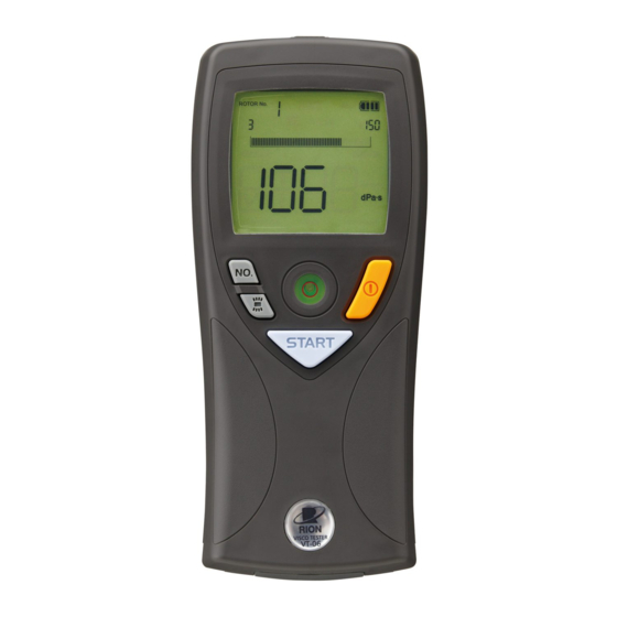
Page 20: Display
Controls and functions Display example... -
Page 21: Operation Key Panel
Controls and functions Operation key panel Rotor selector key Power key Level gauge Back light START key ON/OFF key (Measurement start/stop) - Page 22 Controls and functions Power key Turns power to the unit on and off. The key must be held for at least 1 second to take effect. START key Press to start or stop the measurement. Back light ON/OFF key Turns the backlight on and off. The backlight is automatically turned off when there is no key activity for a certain period.
-
Page 23: Preparations
Preparations Power Supply Using an AC Adapter (Option) To power the unit from an AC adapter, plug the output cable from the adapter into the DC IN jack on the viscotester and plug the AC adapter into an AC outlet rated for 100 V to 240 V AC. Caution To prevent the risk of electric shock, always connect the adapter output cable to the... - Page 24 Preparations DC IN jack AC adapter VA-05J Open the bottom cover To AC outlet, 100 V to 240 V AC, 50/60 Hz...
- Page 25 Preparations Using Batteries Alkaline battery (ALKALINE)- When operating the unit on battery Nickel-metal hydride rechargeable battery power, be sure to set the selector switch (NI-MH) selector switch inside the battery compartment to the correct position for the type of batteries in use (alkaline batteries or nickel-metal hydride rechargeable batteries)
- Page 26 Preparations Checking the battery voltage During viscosity measurement, check the battery status on the display. The num- ber of black segments will decrease as the batteries get used up (4 steps). When battery status indicator is down to 1 segment: Replace the batteries as early as possible with a fresh set.
- Page 27 Preparations Inserting the batteries 1. Remove the battery compartment lid as shown below. 2. Insert four IEC LR6, size AA batteries, paying attention to the polar- ity as shown below. 3. Replace the cover. Battery compartment Push Push the latch in the arrow direction and then lift up Caution to open the lid...
-
Page 28: Attaching The Rotor
Preparations Attaching the Rotor Select a suitable rotor for the viscosity of the sample fl uid (see page 21), and screw the rotor into the rotor mounting shaft. Note • If you do not know the viscosity of the sample fl uid, perform measurement using rotors in the following order: No. -
Page 29: Preparing The Sample Fluid
Preparations Preparing the Sample Fluid Choose the rotor according to the viscosity of the sample fl uid. Depending on the rotor, the required cup size also changes. For No. 1 and No. 2 rotors, use a JIS 300 mL beaker* fi lled with about 350 mL of sample fl uid. For the No. -
Page 30: Measurement
Measurement 1. Hold the viscotester in one hand or mount it to the optional stand (VA-04). Use the level gauge on the unit to verify that the unit is ap- proximately horizontal. Fluid mark 2. Place the rotor in the center of the cup or beaker and fi ll in sample fl uid so that it comes to about the center of the fl uid mark on the rotor. - Page 31 Measurement 5. Press the START key. The indication “RUN” appears on the display and the rotor starts to turn. Hold the unit steady until the viscosity indication has stabilized. When a stable value has been obtained, press the START key again. The rotor stops turning, and the measurement value remains on the display for easy reading.
- Page 32 Measurement Important If the measurement value is below the mea- surement range for the respective rotor, the indication “UNDER” will be shown in the left part of the display under the bar graph. If the measurement value exceeds the measurement range, the indication “OVER”...
- Page 33 Measurement Note Battery life will differ depending on the sample fl uid being measured, but a rough estimate is shown below. Conditions: - IEC LR6 (size AA) alkaline batteries - Measurement time 100 seconds per measure- ment - Sample fl uid viscosity near maximum of respec- tive rotor measurement range Battery life: approx.
-
Page 34: Applied Part
Applied part Rotor extension The supplied foldable rotor extension consists of three 30 cm rods joined by rings. The combined length is 90 cm. When wishing to use the extension at a length of 30 cm or 60 cm, open the connector rings with a pair of pliers, remove the desired number of elements, and rejoin the extension rods. -
Page 35: Specifi Cations
Specifi cations Applicable standards CE marking, WEEE Directive, Chinese RoHS Measurement range (based on combination with the cup specifi ed below “Sample fl uid capacity”) No. 3 rotor: 0.3 dPa•s to 13 dPa•s (resolution: 0.1) No. 1 rotor: 3 dPa•s to 150 dPa•s (resolution: 1) No. - Page 36 Specifi cations Measurement accuracy and reproducibility Measurement accuracy ±10% ±1 digit of indicated value Reproducibility ±5% * Calibrated according to JIS Z 8809:2011 standard liquids for calibrating viscometer * The rounding error resulting from resolution occurs Rotor speed 62.5 rpm Max.
- Page 37 Specifi cations Auto shutdown function (when an AC adapter is not used) If rotor is not turning and no controls are operated for 5 minutes, power is automatically shut off Resume function Last selected rotor number setting is retained during power-off Ambient conditions for use 5°C to 35°C, 10% to 90%RH (no condensation)
- Page 38 Specifi cations Supplied accessories No. 1 rotor (dia. 24 mm × 53 mm × 166 mm) SUS304 No. 2 rotor (dia. 15 mm × 1 mm × 113 mm) SUS304 No. 3 rotor (dia. 45 mm × 47 mm × 160 mm) SUS304 No.
- Page 39 Specifi cations Unit: mm Dimensional Drawings...
- Page 40 Distributor RION CO., LTD. 3-20-41 Higashimotomachi, Kokubunji, Tokyo 185-8533, Japan Manufacturer KYOSAITECHNOS CO., LTD. 4-25-2 Atago, Tama-City, Tokyo 206-0041, Japan No. 58612 16-06...
Need help?
Do you have a question about the VT-06 and is the answer not in the manual?
Questions and answers