
Related Manuals for Rion NL-42


Summary of Contents for Rion NL-42
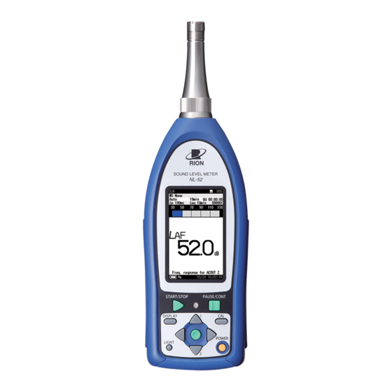
- Page 1 SERIAL INTERFACE MANUAL Sound Level Meter NL-42 / NL-52 3-20-41 Higashimotomachi, Kokubunji, Tokyo 185-8533, Japan http://www.rion.co.jp/english/...
-
Page 3: Organization Of The Nl-42/Nl-52 Documentation
Organization of the NL-42/NL-52 documentation Documentation for the Sound Level Meter NL-42/NL-52 comes in three parts, as listed below. Instruction Manual Describes operating procedures for the NL-42/NL-52, connection and use of peripheral equipment such as a level recorder and printer, and use of the SD memory card. -
Page 5: Organization Of This Manual
Organization of This Manual This manual describes how to use the serial interface built into the NL-42/ NL-52. Besides the RS-232C serial interface standard, the unit also supports USB. However, correct operation in combination with other USB devices is not assured. If possible, you should avoid connecting other USB devices at the same time. -
Page 6: Table Of Contents
Contents Organization of the NL-42/NL-52 documentation ......i Organization of This Manual ............iii Chapter 1 General Information ............1 Outline ....................2 Communication Cutoff ..............3 Sleep mode ................3 ECO setting ................3 Power off ..................3 Auto shutdown ................3 Rated Values ...................4 Chapter 2 RS-232C ................5 Connection to a Computer ..............6... - Page 7 Chapter 4 Commands ..............21 Command ..................22 Command types ...............22 Command format ..............22 Echo back ................24 Result code ................24 Transfer codes ................24 Command list ................25 Command Description .............29 Command example ..............62...
-
Page 9: Chapter 1 General Information
Chapter 1 General Information Contents Outline ....................2 Communication Cutoff ..............3 Sleep mode ................3 ECO setting ................3 Power off ..................3 Auto shutdown ................3 Rated Values ...................4... -
Page 10: Outline
Outline The NL-42/NL-52 incorporate a serial interface. This interface allows the use of a computer to make measurement parameter settings and to control the measurement. It is also possible to send measurement results (current results as well as data stored in the memory of the sound level meter) to the computer for further processing. -
Page 11: Communication Cutoff
Communication Cutoff Sleep mode When sleep mode is enabled, the unit enters the sleep state after the current block has been sent. In the sleep state, the sound level meter does not send or accept commands. ECO setting When ECO setting is selected, it will be enabled after a transmission of current command is completed. -
Page 12: Rated Values
Rated Values Guaranteed values Case Rated Values Remarks Sound level meter re- Result code 0004 (state error) response if Max. 3 s sponse time due to processing reasons Send character inter- Max. 100 ms − Interval until sound After receiving data from the sound level level meter enters meter, wait at least 200 ms before sending Max. -
Page 13: Chapter 2 Rs-232C
Chapter 2 RS-232C Contents Connection to a Computer .............6 Transfer Protocol ................8... -
Page 14: Connection To A Computer
Connection to a Computer Connect the I/O connector on the bottom of the NL-42/NL-52 with a RS-232C connector of a computer, using the optional RS-232C serial I/O cable CC-42R as shown below. The performance of other cables will not be guaranteed. - Page 15 The CC-42R serial I/O cable uses a 9-pin connector (female). The cable is optional. Shield NL-42/NL-52 Computer I/O connector Note When NL-42/NL-52 is connected to a computer, the minimum measurement level of NL-42/NL-52 may rise by the noise from a computer.
-
Page 16: Transfer Protocol
Transfer Protocol Transfer principle: full duplex Sync principle: asynchronous Baud rate: 9600 / 19200 / 38400 / 57600 / 115200 bps Data word length: 8 bit Stop bits: 1 bit Parity check: none Flow control: X parameter... -
Page 17: Chapter 3 Usb
Chapter 3 USB Contents USB ....................10 Operating Environment ..............11 Installing the USB Driver .............12 Installation procedure .............12 Checking the virtual COM port ..........17 Connection to a Computer ............19 Disconnection from the Computer ..........20... -
Page 18: Usb
The NL-42/NL-52 can use a USB connection for operation control and transfer of data. To use the USB interface, a USB driver must be installed on the computer. Please download USB driver from our web site (http://www.rion.co.jp/eng- lish/). Installation and operation procedures are explained in this manual. -
Page 19: Operating Environment
Operating Environment Supported Operating Systems - Microsoft Windows XP Professional (32 bit) - Microsoft Windows 7 Professional (32 bit/64 bit) - Microsoft Windows 8 Pro (32 bit/64 bit) -
Page 20: Installing The Usb Driver
Installing the USB Driver By connecting the NL-42/NL-52 to a computer with a USB cable, the NL- 42/NL-52 can be controlled remotely from the computer, and measurement data can be sent to the computer in real time. To enable use of these functions, you must fi rst download driver software from the RION Corporation web site and install this driver on the computer to be used with the NL-42/NL-52. - Page 21 Installing the USB Driver Follow the wizard to complete the installation. Screens during installation are as follows.
- Page 22 Installing the USB Driver Depending on your environment, [Windows Security] may be dis- played. Click on “Install” or “Continue”. 2. Turn power to the NL-42/NL-52 on, select [I/O] and set [Commu- nication Interface] to “USB”. Important The above steps must be completed before connecting the USB cable.
- Page 23 Installing the USB Driver In case of Windows 7 and Windows 8 When the computer detects the NL-42/NL-52, the device driver software in- stallation is started automatically. When the installation has been completed, USB communication is enabled. In case of Windows XP When the computer detects the NL-42/NL-52, [Found New Hardware Wizard] is started up.
- Page 24 Installing the USB Driver Click on “Continue Anyway”. Click on “Finish”. The driver installation creates a virtual COM port in the computer. For infor- mation on how to verify that the installation was successful, see the section “Checking the virtual COM port” on next page.
-
Page 25: Checking The Virtual Com Port
Installing the USB Driver Checking the virtual COM port 1. After installing the driver, set [Communication Interface] to “USB” at the NL-42/NL-52 and connect the USB cable. 2. Open the Device Manager (“Hardware” tab under “Properties” in My Computer). - Page 26 COM port name. If this is not shown, check the connection between the NL-42/NL-52 and the computer (step 1). If there is an “×” over the icon, the port is not functioning normally. Install the driver again.
-
Page 27: Connection To A Computer
Connection to a Computer Connect the USB connector on the bottom of the NL-42/NL-52 with a USB connector of a computer, using the optional (generic) A - mini B USB cable as shown below. Important Be sure to connect the cable only after selecting the [USB] setting. -
Page 28: Disconnection From The Computer
Disconnection from the Computer NL-42/NL-52 will be recognized as “removable media”. Consequently, the correct procedure as described below must be followed when disconnecting the NL-42/NL-52. 1. Click on the “Safely remove hardware” icon in the right section of the taskbar, and select “Safely remove USB Mass Storage Device - Drive (*1)”. -
Page 29: Chapter 4 Commands
Chapter 4 Commands Contents Commands ..................22 Command types ...............22 Command format ..............22 Echo back ................24 Result code ................24 Transfer codes .................24 Command list ................25 Command description .............29 Command example ..............62... -
Page 30: Command
Command Command types There are two types of commands: setting commands and request com- mands. Setting command This type of command serves for changing the sound level meter status or measurement parameters. Only some commands of this type will produce a response from the sound level meter. - Page 31 Command Permitted items • Lower case may be used instead of upper case. • Upper case may be used instead of lower case. Setting command examples LCD Auto Off,Short[CR][LF] Space after “,” may be omit- Valid ted. lcd auto off, short [CR][LF] Command name in all lower Valid case is permitted.
-
Page 32: Echo Back
This is a response to the situation where the command (setting or 0004 request) cannot be executed in a current situation. Transfer codes The codes (control codes) used for communication with the NL-42/NL-52 are as follows. Code Hex notation Meaning... -
Page 33: Command List
Command Command list S: Setting command (command for making a NL-42/NL-52 setting) R: Request command (command for obtaining status information or mea- surement data from NL-42/NL-52) Communication Command Function See page Echo Echo back (S/R) ......29 Remote Control Remote mode (S/R) ....... 29... - Page 34 Command Display L Display Leq (S/R) ......36 Display L Display LE (S/R) ......36 Display L Display Lmax (S/R) ......37 Display L Display Lmin (S/R) ......37 Display L Display LN1 (S/R) ......37 Display L Display LN2 (S/R) ......
- Page 35 Command Measure Measurement (S/R) ......45 Pause Pause (S/R) ........46 Manual Store Manual store (S) ......46 Measurement Time Preset Manual Measurement time of manual store (S/R) ...... 46 Measurement Time Manual (Num) Measurement time of user setting on manual store (number) (S/R) ..47 Measurement Time Manual (Unit) Measurement time of user setting on manual store (unit) (S/R) ...
- Page 36 Command Timer Auto Interval Timer auto measurement interval (S/R) ..........53 Sleep Mode Sleep mode (S/R) ......53 Measurement Command Function See page Windscreen Correction Windscreen correction (S/R) ..54 Diffuse Sound Field Correction Diffuse sound fi eld correction (S/R) .. 54 Delay Time Delay time (S/R) ......
-
Page 37: Command Description
Command Command Description Communication Echo Echo back Setting ON/OFF of echo back Setting command Echo, p1 Parameter p1= “Off” p1= “On” Request command Echo? Response data Returned value Same as for setting command Remote control Remote mode Setting ON/OFF of remote mode When remote mode is “On”, the key operation of the unit is invalid (only the POWER key and the LIGHT key are effective). -
Page 38: Current Date And Time (S/R)
Command p1= “WR” (when NX-42WR is installed) p1= “RT” (when NX-42RT is installed) p1= “FT” (when NX-42FT is installed) Response data d1= “x.x” (x is 0 to 9) There is no setting command When the parameter p1 is omitted, the request command means “System Version?NL”... -
Page 39: Calibration (S/R)
Command Calibration Calibration Transition to calibration state Setting command Calibration, p1 Parameter p1= “Off” p1= “On” Request command Calibration? Response data Returned value Same as for setting command Cal Mode Calibration mode Setting calibration mode Setting command Mode, p1 Parameter p1= “Internal”... -
Page 40: Index Number (S/R)
Command Index Number Index number Setting index number Setting command Index Number, p1 Parameter p1= 1 to 255 Request command Index Number? Response data Returned value Same as for setting command Key Lock Key lock Setting ON/OFF of key lock Setting command Lock, p1 Parameter... -
Page 41: Backlight (S/R)
Command Backlight Backlight Setting ON/OFF of backlight Setting command Backlight, p1 Parameter p1= “Off” p1= “On” Request command Backlight? Response data Returned value Same as for setting command Backlight Auto Off Backlight auto off Setting time of backlight auto off Setting command Backlight Auto... -
Page 42: Lcd Auto Off (S/R)
Command LCD Auto Off LCD auto off Setting time of LCD auto off Setting command Auto Off, p1 Parameter p1= “Off” p1= “Long” (10 minutes) p1= “Short” (1 minute) Request command LCD Auto Off? Response data Returned value Same as for setting command Backlight Brightness Backlight brightness Setting backlight brightness... -
Page 43: Sd Memory Card Capacity (R)
Command SD Card Total Size SD memory card capacity Request capacity of SD memory card Request command SD Card Total Size? Response data d1= 0 to 32768 (MByte) There is no setting command SD Card Free Size SD memory card free space Request free space of SD memory card Request command SD Card... -
Page 44: Display Additional Processing (S/R)
Command Display Ly Display additional processing Setting ON/OFF of additional processing display Setting command Display Ly, p1 Parameter p1= “Off” p1= “On” Request command Display Response data Returned value Same as for setting command Display Leq Display L Setting ON/OFF of L display Setting command Display... -
Page 45: Display L N1 (S/R)
Command Display Lmax Display L Setting ON/OFF of L display Setting command Display Lmax, p1 Parameter p1= “Off” p1= “On” Request command Display Lmax? Response data Returned value Same as for setting command Display Lmin Display L Setting ON/OFF of L display Setting command Display... -
Page 46: Display L N3 (S/R)
Command Display LN2 Display L Setting ON/OFF of L display Setting command Display LN2, p1 Parameter p1= “Off” p1= “On” Request command Display LN2? Response data Returned value Same as for setting command Display LN3 Display L Setting ON/OFF of L display Setting command Display... -
Page 47: Display L
Command Display LN5 Display L Setting ON/OFF of L display Setting command Display LN5, p1 Parameter p1= “Off” p1= “On” Request command Display LN5? Response data Returned value Same as for setting command Percentile 1 Percentile of L Setting percentile of L Setting command Percentile 1, p1... -
Page 48: Percentile Of L N3
Command Percentile 3 Percentile of L Setting percentile of L Setting command Percentile 3, p1 Parameter p1= 10 to 990 (10 step) * The parameter means 1% to 99% Request command Percentile Response data Returned value Same as for setting command Percentile 4 Percentile of L Setting percentile of L... -
Page 49: Display Time-Level (S/R)
Command Display Time Level Display time-level Setting ON/OFF of time-level display Setting command Display Time Level, p1 Parameter p1= “Off” p1= “On” Request command Display Time Level? Response data Returned value Same as for setting command Time Level Time Scale Time scale of time-level display Setting time scale of time-level display Setting command... -
Page 50: Output Level Range Lower (S/R)
Command Output Level Range Lower Output level range lower Setting output level range lower The value cannot be set the value of “Output Level Range Upper” or more Setting command Output Level Range Lower, p1 Parameter p1= 20 to 80 (10 dB steps) Request command Output Level... -
Page 51: Communication Interface (S/R)
Command Communication Interface Communication interface Setting communication interface Setting command Communication Interface, p1 Parameter p1= “Off” p1= “USB” p1= “RS232C” Request command Communication Interface? Response data Returned value Same as for setting command Baud Rate RS-232C baud rate Setting RS-232C baud rate Setting command Baud Rate, p1... -
Page 52: Comparator Level (S/R)
Command Comparator Level Comparator level Setting comparator level Setting command Comparator Level, p1 Parameter p1= 25 to 130 (1 steps) Request command Comparator Level? Response data Returned value Same as for setting command Comparator Channel Comparator band Setting comparator band Setting command Comparator Channel, p1... -
Page 53: Store Name (S/R)
Command Store Name Store Name Setting store name Setting command Store Name, p1 Parameter p1= 0 to 9999 Request command Store Name? Response data Returned value Same as for setting command Manual Address Manual store address Setting manual store address Setting command Manual Address, p1... -
Page 54: Pause (S/R)
Command Pause Pause Pause a measurement Setting command Pause, p1 Parameter p1= “Pause” p1= “Clear” Request command Pause? Response data Returned value Same as for setting command Manual Store Manual store Storing the calculated value in manual store Setting command Manual Store, p1 Parameter... -
Page 55: Measurement Time Of User Setting On Manual Store (Number) (S/R)
Command Measurement Time Manual (Num) Measurement time of user setting on manual store (number) Setting value when “Measurement Time Preset” command parameter is “Manual” on manual store mode Setting command Measurement Time Manual (Num), p1 Parameter p1= 1 to 59 (Time unit is s [second] or m [minute]) p1= 1 to 24 (Time unit is h [hour]) -
Page 56: Total Measurement Time Of User Setting On Auto Store (Number) (S/R)
Command p1= “8h” p1= “24h” p1= “Manual” (user setting) Request command Measurement Time Preset Auto? Response data Returned value Same as for setting command Measurement Time Auto (Num) Total measurement time of user setting on auto store (number) Setting value when “Measurement Time Preset”... -
Page 57: Measurement (Operation) Start Time (R)
Command Measurement Start Time Measurement (operation) start time Request measurement (operation) start time Request command Measurement Start Time? Response data d1/d2/d3 d4:d5:d6 Returned value d1= 2012 to 2099 (year) d2= 1 to 12 (month) d3= 1 to 31 (date) d4= 0 to 23 (hour) d5= 0 to 59 (minute) -
Page 58: L P Store Interval (S/R)
Command Lp Store Interval store interval Setting L store interval Setting command Store Interval, p1 Parameter p1= “Off” p1= “100ms” p1= “200ms” p1= “1s” p1= “Leq1s” Request command Lp Store Interval? Response data Returned value Same as for setting command Leq Calculation Interval Preset calculation interval Setting L... -
Page 59: Eq Calculation Interval Of User Setting
Command Leq Calculation Interval (Num) calculation interval of user setting (number) Setting value when “Leq Calculation Interval Preset” command pa- rameter is “Manual” Setting command Calculation Interval (Num), p1 Parameter p1= 1 to 59 (Time unit is s [second] or m [minute]) p1= 1 to 24 (Time unit is h [hour]) Request command Leq... -
Page 60: Timer Auto Start Time (S/R)
Command Timer Auto Start Time Timer auto start time Setting timer auto start time Setting command Timer Auto Start Time, p1/p2/p3 p4:p5:p6 Parameter p1= 2012 to 2099 (year) p2= 1 to 12 (month) p3= 1 to 31 (date) p4= 0 to 23 (hour) p5= 0 to 59 (minute) -
Page 61: Timer Auto Measurement Interval (S/R)
Command Timer Auto Interval Timer auto measurement interval Setting timer auto measurement interval Setting command Timer Auto Interval, p1 Parameter p1= “Off” p1= “5m” p1= “10m” p1= “15m” p1= “30m” p1= “1h” p1= “8h” p1= “24h” Request command Timer Auto Interval? Response data Returned value... -
Page 62: Windscreen Correction (S/R)
Command Measurement Windscreen Correction Windscreen correction Setting windscreen correction Setting command Windscreen Correction, p1 Parameter p1= “Off” p1= “WS-10” p1= “WS-15” p1= “WS-16” Request command Windscreen Correction? Response data Returned value Same as for setting command Diffuse Sound Field Correction Diffuse sound fi eld correction Setting ON/OFF of diffuse sound fi eld correction Setting command... -
Page 63: Delay Time (S/R)
Command Delay Time Delay time Setting delayed measurement time Setting command Delay Time, p1 Parameter p1= “Off” p1= “1s” p1= “3s” p1= “5s” p1= “10s” Request command Delay Time? Response data Returned value Same as for setting command Back Erase Back erase Setting back erase interval Setting command... -
Page 64: Frequency Weighting Of Main Channel (S/R)
Command Operation Frequency Weighting Frequency weighting of main channel Setting frequency weighting of main channel Setting command Frequency Weighting, p1 Parameter p1= “A” p1= “C” p1= “Z” Request command Frequency Weighting? Response data Returned value Same as for setting command Frequency Weighting (Sub) Frequency weighting of sub channel Setting frequency weighting of sub channel... -
Page 65: Time Weighting Of Sub Channel (S/R)
Command Time Weighting (Sub) Time weighting of sub channel Setting time weighting of sub channel Setting command Time Weighting (Sub), p1 Parameter p1= “F” p1= “S” p1= “I” (when NX-42EX is installed) Request command Time Weighting (Sub)? Response data Returned value Same as for setting command Ly Type Additional processing type... -
Page 66: Underrange L Overload L (R)
Command Underrange Leq Underrange L Request presence of underrange information in processed data Request command Underrange Leq? Response data Returned value d1= “Off” (there is no information) d1= “On” (there is information) There is no setting command Overload Lp Overload L Request presence of overload L information Request command Overload... -
Page 67: Overload Output (R)
Command Overload Output Overload output Request presence of overload output information Request command Overload Output? Response data Returned value d1= “Off” (there is no information) d1= “On” (there is information) There is no setting command calculation data Select calculation date for percentile sound level L Setting command TRM, p1 Parameter... -
Page 68: Output Displayed Value (R)
Command Data output Output displayed value Send the request command at one second interval or longer. Request command DOD? Response data d1,d2,...,d14 Main channel L Returned value d1 = “xxx.x” Main channel L d2 = “xxx.x” Main channel L d3 = “xxx.x” Main channel L d4 = “xxx.x”... -
Page 69: Continuous Output (R)
Command DRD (only when optional NX-42EX is installed) Continuous output Data are sent periodically to the computer every 100 msec. If the store mode is Auto, DRD? is available when the L store interval setting is 100 msec. To stop the data transfer, send the stop request transfer code <SUB> (hexadecimal notation: 1A When the [Wave Rec Mode] on the Wave recording screen is selected, the DRD? is not available. -
Page 70: Command Example
Command Command example The example of a setting by a command is shown. Using a request command after a setting is recommended. Basic setting Setting the Frequency Weighting to “A” Frequency Weighting, A Setting the Time Weighting to “F(Fast)” Time Weighting, F Setting the Output Level Range Upper to “120dB”... - Page 71 Command When operating manual store Setting the Store Mode to “Manual” Store Mode, Manual Setting the Store Name to “0200” Store Name, 200 Setting the Measurement Time to “15min” Measurement Time Preset Manual, 15m Measurement start / stop Measure, Start Measure, Stop Saving of the store result Manual...
- Page 72 No. 55776 13-06...
Need help?
Do you have a question about the NL-42 and is the answer not in the manual?
Questions and answers