Table of Contents
Advertisement
Quick Links
Download this manual
See also:
Instruction Manual
Advertisement
Chapters
Table of Contents

Related Manuals for Rion NA-28


Summary of Contents for Rion NA-28
-
Page 1: Sound Level Meter
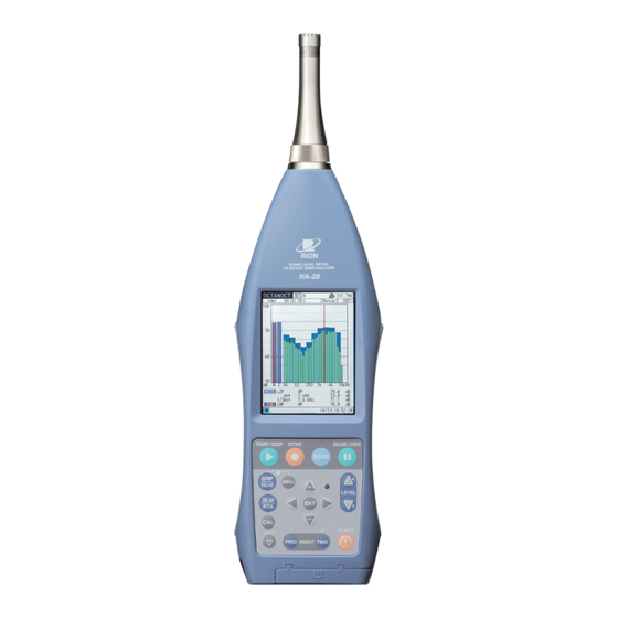
INSTRUCTION MANUAL SOUND LEVEL METER NA-28 3-20-41 Higashimotomachi, Kokubunji, Tokyo 185-8533, Japan http://www.rion.co.jp/english/... -
Page 3: Organization Of The Na-28 Documentation
Organization of the NA-28 Documentation Documentation for the Sound Level Meter NA-28 comes in three parts, as listed below. Instruction Manual (this document) Describes operating procedures for the Sound Level Meter NA-28, connec- tion and use of peripheral equipment such as a level recorder and printer, and use of the memory card. -
Page 5: Organization Of This Manual
Organization of This Manual This manual describes the features, operation and other aspects of the Sound Level Meter NA-28 (with 1/3 octave analysis function). If the unit is used together with other equipment to confi gure a measurement system, consult the documentation of all other components as well. - Page 6 Memory Card Explains how to use a memory card with the unit. Input/Output Connectors Explains the input and output connectors of the unit. Default Settings Lists the factory default settings of the unit. Setup File Explains how to start up the unit using settings saved in a setup fi le. Optional Accessories Explains how to use the optional microphone extension cable, printer, and level recorder with the unit.
- Page 7 FOR SAFETY In this manual, important safety instructions are specially marked as shown below. To prevent the risk of death or injury to persons and severe damage to the unit or peripheral equipment, make sure that all instructions are fully understood and observed.
- Page 9 (Sound level and sound pressure level are expressed uniformly as sound pres- sure level, distinguished by the use of frequency weighting.) Display on the time weighting characteristics Measurement value NA-28 F, S, 10 ms A-weighted sound pressure level A10ms Sound pressure...
- Page 10 viii...
- Page 11 Quantifi er Notation of Sound Level Meter NA-28 According to International Standards and JIS (Excerpts from ISO 1996, 3891, IEC 61672-1:2002, JIS Z 8202, 8731) NA-28 Fre que ncy J IS IS O De s cription nota tion we ighting...
- Page 13 Precautions Operate the unit only as described in this manual. The NA-28 is a precision instrument. Protect it from shocks and vibrations. Take special care not to touch the microphone diaphragm. The diaphragm is a very thin metal fi lm which can easily be damaged.
- Page 14 To ensure continued accuracy, have the unit checked and serviced at regular intervals. When using the unit for commercial purposes or for certifi cation, offi cial certifi cation is required every fi ve years. Contact the supplier. Dispose of the unit and of batteries only according to national and local regulations at the place of use.
-
Page 15: Table Of Contents
Contents Organization of the NA-28 Documentation ........i Organization of This Manual ............iii Outline ....................1 Controls and Functions ..............3 Front View .................3 Microphone/Preamplifi er .............3 Display .................3 Operation key panel .............4 Bottom View ................7 Rear View ..................8 Preparations ..................9 Power ..................9... - Page 16 Calibration ..................33 Electrical calibration ............33 Power On/Off ................37 To turn the unit on ..............37 To turn the unit off .............38 Reading the Display ..............39 Sound level meter mode screen ..........39 Analyzer mode screen .............44 T-L (Time/Level) display screen ..........44 Numeric display screen ............45 Indicator messages ..............46 Menu List Screen ..............47 System ................47...
- Page 17 Store Operation ................81 Inserting and Removing the CF Card ........84 Manual ..................85 Memory Store ..............85 Auto1 ..................91 Auto2 ..................97 Memory Card ................99 Using a memory card ............99 Input/Output Connectors ............. 103 AC OUTPUT ................. 103 DC OUTPUT ................. 105 TRIG IN/COMP OUT jack ............
-
Page 19: Outline
Outline The Sound Level Meter NA-28 allows octave and 1/3 octave band analysis in real time. It conforms to legal requirements for quantity measurements and to JIS and IEC standards. It supports diffuse sound fi eld measurements and also meets standard requirements when the supplied windscreen is mounted. - Page 20 Outline The Sound Level Meter NA-28 allows the following quantity measure- ments. Main processing (sound level meter mode, analyzer mode) Simultaneous measurement of all items with selected time weighting and frequency weighting characteristics Sound level Equivalent continuous sound level Sound exposure level...
-
Page 21: Controls And Functions
Controls and Functions Front View Microphone/ Preamplifier SOUND LEVEL METER 1/3 OCTAVE BAND ANALYZER NA-28 Display START/STOP STORE PAUSE/CONT MODE MENU LEVEL Operation key panel POWER LIGHT FREQ WEIGHT TIME Infrared remote control sensor Memory card slot cover Microphone/Preamplifi er The microphone/preamplifi er unit can be detached from the main unit and connected via an optional extension cable. -
Page 22: Operation Key Panel
Controls and Functions Operation key panel START/STOP key STORE key MODE key START/STOP STORE PAUSE/CONT PAUSE/CONT key Key lock MODE Indicator LED GRP/NUM key MENU MENU key LEVEL keys LEVEL SLM/RTA key / / keys CAL key ENT key POWER LIGHT LIGHT key POWER key... - Page 23 Controls and Functions LEVEL keys (Level range switching keys) Serve for selecting the level range for measurement. In sound level meter mode, the following six settings are available. 20 to 80, 20 to 90, 20 to 100, 20 to 110, 20 to 120, 30 to 130 dB In analyzer mode, the following six settings are available.
-
Page 24: Mode
Controls and Functions CAL key (Calibration key) This key is used for calibration of the unit and for level calibration of connected equipment. SLM/RTA key (Sound level meter/Real-time analyzer key) This key switches between sound level meter mode and real-time analyzer mode. -
Page 25: Bottom View
Controls and Functions Bottom View Cover Bottom External power supply jack USB port TRIG IN/COMP OUT jack AC OUTPUT jack DC OUTPUT jack Cover This cover protects the connectors on the bottom during transport or stor- age. Removing the cover gives access to the connectors shown above. External power supply jack The supplied AC adapter NC-94A can be connected here for powering the unit from an AC outlet. -
Page 26: Rear View
Controls and Functions Rear View Name plate Tripod mounting thread Battery compartment Name plate Shows various information including model number of the unit, microphone number, preamplifi er number, serial number, and date of manufacture. Tripod mounting thread The unit can be mounted on a camera tripod using this thread. Battery compartment Four batteries (IEC R14, size C) are inserted here. -
Page 27: Preparations
Preparations Power The NA-28 can be powered by four IEC R14, size C batteries (alkaline or manganese) or the AC adapter NC-94A. Rechargeable batteries may also be used, but the NA-28 does not have a facility for charging the batteries. -
Page 28: Ac Adapter
Preparations Important Take care not to reverse the (+) and (-) polarity when inserting the batteries. Always replace all four batteries together. To prevent the risk of damage, do not mix old and new batteries or batteries of different type. To prevent the risk of battery fl uid leakage, re- move the batteries from the unit when the unit is not used. -
Page 29: Windscreen (Ws-10)
Preparations Windscreen (WS-10) When making outdoor measurements in windy weather or when measuring air conditioning equipment or similar, wind noise at the microphone can cause measurement errors. Such effects can be reduced by using the wind- screen WS-10. You can use a compensation feature to ensure fl at frequency response when the windscreen WS-10 is mounted. -
Page 30: Diffuse Field Correction
Preparations Diffuse Field Correction You can use a compensation feature to ensure fl at frequency response in a diffuse sound fi eld. 1. Select [Measurement] from the menu list and press the ENT key. 2. Select [Diffuse Field Correction] from the menu and set it to ON. 3. -
Page 31: Memory Cards (Cf Card) And Program Cards
Measurement data can be stored on a memory card for use and further pro- cessing in a computer. Optional program cards can also be used for loading software into the NA-28 to expand the measurement functions of the unit. Inserting a card... -
Page 32: Microphone Extension Cables (Ec-04 Series)
Preparations Microphone Extension Cables (EC-04 series) Be sure to turn power to the unit OFF before separating the microphone from the main unit. To reduce measurement deviations due to refraction effects and the acoustic infl uence of the operator, the microphone can be detached from the unit and connected via an extension cable. - Page 33 Preparations 2. Connect the extension cable to the preamplifi er and to the main unit and fasten the connectors with the fastening screw. 3. When mounting the microphone on a tripod, fi rst fasten the micro- phone holder (supplied with the extension cable) to the tripod. Then insert the extension cable connector into the microphone holder.
-
Page 34: Connection To A Printer
Preparations Connection to a Printer The USB port on the bottom of the unit can be used for connection to a USB printer, using the printer connection cable. DC 5-6V USB port TRIG IN/ COMP OUT OUTPUT Open cover on bottom To printer Printer connection cable Connection to a Level Recorder (LR-07, LR-20A) -
Page 35: Connection To A Computer
Preparations Connection to a Computer The USB port on the bottom of the unit can be used for connection to the RS-232C interface or USB port of a computer, using the optional serial I/O cable or USB connection cable. DC 5-6V USB port TRIG IN/ COMP OUT... -
Page 36: Setting The Date And Time
Preparations Setting the Date and Time The NA-28 incorporates a clock which allows recording the date and time along with measurement data. Set the date and time as described below. 1. Press the POWER key to turn the unit on. - Page 37 Preparations keys to select [Time setting] and press ENT key System menu screen keys to select item to set Use ENT key to select digit keys to change value Press ENT key to move on Press ENT key to accept System -- Time Setting screen...
- Page 38 Preparations Note An internal rechargeable backup battery serves to keep clock setting on the unit and to store measuring data in internal memory. Those data and clock set- ting will be gone if the unit is not used for a certain period or the backup battery is empty.
-
Page 39: Measurement In A Dark Location
Preparations Measurement in a dark location Pressing the LIGHT key will turn on the display backlight, for easier read- ing in a dark location. The backlight operation pattern can be controlled via a menu, as follows. 1. Press the MENU key to bring up the menu list screen. 2. -
Page 40: Sub Channel Settings
Preparations Sub Channel Settings To use the sub channel, you must make certain settings on a menu screen. 1. Press the MENU key to bring up the menu list screen. 2. Use the keys to select [Measurement] and press the ENT key. -
Page 41: Trigger Mode Settings
Preparations Trigger Mode Settings The NA-28 offers a trigger mode whereby measurement is initiated by one of three kinds of trigger: time trigger (time-controlled triggering), level trig- ger (sound level controlled triggering), and external trigger (triggering by an external signal). - Page 42 Preparations Time Trigger Setting For Auto1 1. Press the MENU key to bring up the menu list screen. 2. Use the keys to select [Store] and press the ENT key. 3. Use the keys to select [Store Mode] and press the ENT key.
- Page 43 Preparations For Auto2 1. Press the MENU key to bring up the menu list screen. 2. Use the keys to select [Store] and press the ENT key. 3. Use the keys to select [Store Mode] and press the ENT key. 4.
-
Page 44: Sleep Mode
Preparations Sleep Mode If time trigger has been selected for the Auto1 or Auto2 mode, you can enable sleep mode (power-saving standby mode). When sleep mode is enabled, the unit will enter a power-saving standby condition before the measurement is started and during intervals between measurements. - Page 45 Preparations In the measurement standby condition, the indicator LED fl ashes in blue using the following pattern. 0.1 second intervals 5 seconds Lit Out Lit Lit Out Lit...
- Page 46 Preparations Level Trigger Setting 1. Press the MENU key to bring up the menu list screen. 2. Use the keys to select [Measurement] and press the ENT key. 3. Use the keys to select [Trigger Mode]. 4. Use the keys to select [Level * ] and press the ENT key. Level1: Measurement starts when trigger level is exceeded and ends when preset measurement time has elapsed.
- Page 47 Preparations External Trigger Setting 1. Press the MENU key to bring up the menu list screen. 2. Use the keys to select [Measurement] and press the ENT key. 3. Use the keys to select [Trigger Mode] and press the ENT key. 4.
-
Page 48: Comparator Output
Preparations Comparator Output This is an open collector output that can be used to control external equip- ment. 1. Press the MENU key to bring up the menu list screen. 2. Use the keys to select [I/O(Input/Output)] and press the ENT key. -
Page 49: About The Comparator Output
Preparations About the comparator output When the sub channel is OFF, the comparator will not function if sub chan- nel is selected as comparator band. Similarly, if analyzer mode is set for simultaneous analysis of octave and 1/3 octave bands, and 16 kHz or 20 kHz is selected as comparator band, the comparator will not function. -
Page 50: Language Selection
Preparations Language Selection The language used for displaying messages and menus can be selected as follows. 1. Press the MENU key to bring up the menu list screen. 2. Use the keys to select [System (Language)] and press the ENT key. 3. -
Page 51: Calibration
Calibration Before starting a measurement, the NA-28 must be calibrated. There are two types of calibration, namely electrical calibration using an internally gener- ated signal and acoustic calibration using an external sound calibrator. Electrical calibration Calibration is carried out using a signal generator (1 kHz, sine wave) built into the unit. - Page 52 (maximum value -6 dB). A calibration signal is supplied at the AC OUTPUT and DC OUTPUT jack on the bottom panel of the NA-28. 3. Press the CAL key once more to return to the measurement screen. Note...
- Page 53 1. Turn off the Sound Calibrator NC-74. 2. Turn on the NA-28. 3. At the measurement screen, use the FREQ WEIGHT key to set fre- quency weighting for the main channel to '' A ''.
- Page 54 STORE key. The indication will change to '' A coustic Calibration''. 9. Use the keys to adjust the reading of the NA-28 to the value shown below. Sound Calibrator NC-74: 94.0 10. Press the CAL key. The measurement screen returns.
-
Page 55: Power On/Off
MODE Indicator LED MENU LEVEL POWER LIGHT POWER key FREQ WEIGHT TIME During initialization, the "R" in the Rion logo rotates. NA-28 SOUND LEVEL METER 1/3 OCTAVE BAND ANALYZER IPL: 0.4.0085 CPU: 0.4.0085 Version 0.4 RION Co.,Ltd. All rights reserved. -
Page 56: To Turn The Unit Off
Opening the battery compartment as shown below gives access to a switch labeled '' A -B''. Setting this switch to the ''B'' position allows the NA-28 to be turned on simply by supplying power to the external power supply jack. In this case, the POWER switch on the operation panel of the NA-28 has no effect. -
Page 57: Reading The Display
Reading the Display Sound level meter mode screen The illustration below shows all elements of the display for explanation pur- poses. In actual operation, such a screen will not be shown, and the size and font of the actual display may be slightly different. Diffuse sound correction Comparator ON/Comparator level Trigger mode... - Page 58 Reading the Display Address Shows the current memory address. In manual store mode, the indication is red if there are data in that address. In Auto1 mode, the store cycle is shown. Store mode Shows the selected mode for storing data in memory (Manual, Auto1, or Auto2).
- Page 59 Reading the Display Current date and time Shows the current date and time. Key lock Pressing the GRP/NUM key and MENU key simultaneously activates the key lock condition and causes this symbol to appear. To cancel the condi- tion, press the GRP/NUM key and MENU key once more together. Battery status When the unit is operated on battery power, you should regularly check this indication.
-
Page 60: Main Channel Frequency Weighting
Reading the Display Main channel time weighting Indicates the main channel time weighting characteristic. F: Fast, S: Slow, : 10 ms Main channel frequency weighting Indicates the main channel frequency weighting characteristic. A: A-weighting, C: C-weighting, Z: Flat response Measurement in progress symbol When a measurement is in progress, the symbol fl ashes. -
Page 61: Trigger Mode
Reading the Display Trigger mode Controls the measurement and memory store start behavior. Available modes are Level1, Level2, Time, and EXT. Diffuse sound correction Indicates that the unit has been set up for measurement in a diffuse sound fi eld. -
Page 62: Analyzer Mode Screen
Reading the Display Analyzer mode screen An example for the OCT & 1/3 OCT analysis screen is shown below. Use the keys of the keys to move to the target fre- quency. Comparator indication Comparator band Cursor Main channel AP level Sub channel AP level Comparator level Frequency and level... -
Page 63: Numeric Display Screen
Reading the Display Numeric display screen Examples for OCT, 1/3 OCT, and OCT·1/3 OCT analysis screens are shown below. Numeric display (1/3 OCT) screen Numeric display (OCT) screen Frequencies that are currently not displayed keys. can be called up with the Numeric display (OCT, 1/3 OCT) screen... -
Page 64: Indicator Messages
Reading the Display Indicator messages When keys such as START/STOP or STORE are pressed, indicator messages such as shown below will appear on the display for about 1 second. When START/STOP key was pressed and processing has started When START/STOP key was pressed and processing has ended When STORE key was pressed (store address is also shown) -
Page 65: Menu List Screen
Reading the Display Menu List Screen Pressing the MENU key brings up the menu list screen as shown below. Use keys to select the desired menu and press the ENT key. Menu list screen System Use the keys to select [System (Language)] and press the ENT key. - Page 66 Reading the Display Read/Save Setting Bring the cursor to [Read/Save Setting] and press the ENT key. The [System -- Setting] screen appears. Return MENU keys to select the item and press the ENT key. The [System -- Settings -- Save] screen appears. keys to select the item and press the ENT key.
- Page 67 Reading the Display Time setting Bring the cursor to [Time Setting] and press the ENT key. The [System -- Time Setting] screen appears. Use ENT key to select digit and keys to change value Long push of makes values change faster Press ENT key to accept setting [System -- Time Setting] screen Program Information...
-
Page 68: Display
Reading the Display Display Use the keys to select [Display] and press the ENT key. The display menu screen appears. MAX Hold ON/OFF (can be selected in analyzer mode) ON/OFF ON/OFF Lmax ON/OFF Lmin ON/OFF LN1 (L01 to L99) ON/OFF LN2 (L01 to L99) ON/OFF LN3 (L01 to L99) -
Page 69: I/O (Input/Output)
Reading the Display I/O (Input/Output) Use the keys to select [I/O (Input/Output)] and press the ENT key. The Input/Output menu screen appears. AC Out OFF/MAIN/SUB DC Out OFF/MAIN/SUB Comparator ON/OFF USB Communication ON/OFF Remote Control ON/OFF Backlight Brightness Dark/Bright Backlight Auto-Off 30 s/3 m/Cont Beep ON/OFF Index... - Page 70 Reading the Display Comparator menu level Use the keys to select [Comparator] and press the ENT key. The following menu appears. Comparator ON/OFF Comparator Level 25 to 130 dB (1-dB steps) Comparator Band SUB AP/MAIN AP/12.5 Hz/16 Hz/20 Hz/25 Hz ...
-
Page 71: Store
Reading the Display Store Use the keys to select [Store] and press the ENT key. The store menu appears. Store Mode Manual/Auto1/Auto2 Store Name MAN_ **** AU1_ **** AU2_ **** **** is a 4-digit number from 0000 to 9999 Sampling Period (SLM/RTA) (only shown in Auto1 mode) SLM: 100 ms RTA:... -
Page 72: Measurement
Reading the Display Measurement Use the keys to select [Measurement] and press the ENT key. The measurement menu appears. Wind Screen Correction ON/OFF Measurement Time Auto1 1 s to 1000 h Auto2 (normal measurement) 1 s to 24 h Back-Erase OFF/5 s Delay Time 1 to 10 s... - Page 73 Reading the Display Trigger mode menu level Use the keys to select [Trigger Mode] and press the ENT key. The following menu appears. Available trigger mode settings are Level 1, Level 2, Time, and EXT. It is available to set the trigger interval when the store mode is Auto 2...
-
Page 74: Print
Reading the Display Sub channel menu level Use the keys to select [Sub Channel] and press the ENT key. The following menu appears. Measurement-SUB Chnnel Measurement-SUB Chnnel screen Print Use the keys to select [Print] and press the ENT key. The print menu screen appears. -
Page 75: Recall
Reading the Display Recall Use the keys to select [Recall] and press the ENT key. The Select File menu appears. Select File menu screen... -
Page 76: Max Hold
Reading the Display Menu List Items System CF Card Format Read/Save Settings [v]---------- Load Default Group Save for CF card [v]---------------- List of setting groups on CF card Group Loading/Delete for CF card [v]---- List of setting groups on CF card Time Setting ----------------Year/Month/Day Hour:Min:Sec Program Information [v]----------------- Model, Version... -
Page 77: Measurement
Measurement When using the NA-28 in a mode other than "sound level measurement", all processing functions provided by the unit (L ) are car- ried out simultaneously. (However, for the sub channel, only the additional processing function set to "ON" in the menu screen is carried out.) For ex- ample, when equivalent continuous sound level measurement is selected, the sound exposure level and percentile level are also determined. - Page 78 Measurement 2. Use the FREQ WEIGHT key to select the frequency weighting characteristic. For normal sound level measurements, select the "A" setting. When LZ (Flat) is selected for display, the sound pressure level from 10 Hz to 20 kHz is measured with fl at characteristics. When LC (Flat) is selected for display, the sound pressure level from 31.5 Hz to 8 kHz is measured with fl at characteristics.
-
Page 79: Equivalent Continuous Sound Level (L Aeq ) Measurement
Measurement 5. The level indication shows the currently measured sound level (sound pressure level). The reading is updated once every second. The PAUSE/CONT key can be used to stop and resume the updat- ing of level indication. In sound level meter mode, the bar graph indication will be updated also during pause. - Page 80 Measurement Note The NA-28 performs high-speed sampling of the sound pressure waveform (15.6 µs; 20.8 µs when octave and 1/3 octave analysis is performed simul- taneously) to determine L and L . It is therefore not affected by dynamic characteristics.
- Page 81 Measurement 6. Set the measurement time from the menu. Press the MENU key to bring up the menu list screen. 7. Use the keys to select [Measurement] and press the ENT key. The measurement menu screen appears. 8. Use the keys to select [Measurement time] and press the ENT key.
- Page 82 Measurement 11. Use the keys to select [Leq] and press the ENT key. 12. Use the keys to select ON and press the ENT key. Set Leq to ON Display menu screen 13. Press the START/STOP key to return to the measurement screen. For information about how to use the back-erase function to exclude data, refer to page 76.
- Page 83 Measurement During measurement, the PAUSE/CONT key can be used to pause and resume the measurement. During pause, the pause symbol ( ) is shown. (The paused interval and the back-erase interval are not included in the measurement time.) If the back-erase function was enabled in steps 7 and 8, using the Time-Level screen is convenient.
-
Page 84: Sound Exposure Level (Lae ) Measurement
Measurement Sound Exposure Level (L ) Measurement The procedure for sound exposure level measurement is similar to that for equiva- lent continuous sound level measurement, but the menu item selection differs. Preparations as described in the "Preparations" chapter must be completed fi rst. 1. - Page 85 Measurement Important During measurement, the LEVEL keys, FREQ WEIGHT key, and TIME WEIGHT key function as markers. The START/STOP key, MODE key, PAUSE/CONT key, LIGHT key, and POWER key are operative. Be sure to complete all settings before starting the measurement. During measurement, the PAUSE/CONT key can be used to pause and resume the measurement.
-
Page 86: Maximum Sound Level (L ) And Minimum Sound Level (L Min ) Measurement
Measurement Maximum Sound Level (L ) and Minimum Sound Level ) Measurement The procedure for maximum sound level and minimum sound level measure- ment is similar to that for equivalent continuous sound level measurement, but the menu item selection differs. Preparations as described in the "Preparations"... - Page 87 Measurement While the measurement is in progress, the symbol fl ashes and the elapsed time is displayed. When the measurement time has elapsed, the measurement is terminated automatically. To terminate the measurement before the allocated time, press the START/STOP key. If signal overload or an under-range condition occurs at least once during measurement, the indication OVER or UNDER appears, to indicate that overload or under-range data are comprised in the...
-
Page 88: Max /L Min Type
Measurement Note During measurement, you can use the MODE key to check the equivalent continuous sound level as cur- rently calculated. (This applies only to the numeric level display. The bar graph shows the sound level.) After the measurement is completed, changing the frequency weighting (A/C/Z), time weighting (Fast/ Slow) or other settings has no effect on the displayed processing results. -
Page 89: Percentile Sound Level
Measurement Percentile Sound Level (L ) Measurement The procedure for percentile sound level measurement is similar to that for equiva- lent continuous sound level measurement, but the menu item selection differs. Preparations as described in the "Preparations" chapter must be completed fi rst. 1. - Page 90 Measurement If signal overload or an under-range condition occurs at least once during measurement, the indication OVER or UNDER appears, to indicate that overload or under-range data are comprised in the processed values. Important During measurement, the LEVEL keys, FREQ WEIGHT key, and TIME WEIGHT key function as markers.
-
Page 91: Additional Processing Value
Additional Processing Value (L ) Measurement peak Atm5 When the NA-28 is in sound level meter mode and the sub channel is ON, the following processing functions are available in addition to L , and L Peak sound level peak... - Page 92 Measurement 6. Select L peak 7. Press the START/STOP key to return to the measurement screen. 8. Use the LEVEL keys to set the level range. Choose a setting in which the bar graph indication registers to about the middle of the range.
- Page 93 Measurement Important is the time-weighted sound level. Processing for this value begins when the START/STOP key is pressed, and the display is updated ac- cordingly. The display will not be updated when processing has stopped. Therefore using the MANUAL mode is recommended for L Note During measurement, you can use the MODE key to check the equivalent continuous sound level as...
-
Page 94: Back-Erase Function
Measurement Back-Erase Function When a measurement is being carried out and data are being processed, the PAUSE/CONT key can be used to pause the measurement. Normally, data up to the point at which the PAUSE/CONT key was pressed will be included in processing, but the back-erase function makes it possible to exclude (back- erase) data from a 5-second interval before the key was pressed. -
Page 95: Marker
Measurement Marker During processing of Leq and other values, it is possible to add markers to the data. 1. Select the store mode on the main menu. Also set the required measurement parameters such as frequency weighting and time weighting. 2. -
Page 96: Max Hold
Measurement Max Hold This function retains the maximum value for one second, for easier reading of the changing bar graph indication. 1. Press the MENU key to bring up the menu list screen. 2. Select [Display] to bring up the display menu screen. 3. -
Page 97: Delayed Measurement
Measurement Delayed Measurement The NA-28 allows setting a delay time to be inserted before the actual start of the measurement. 1. Press the MENU key to bring up the menu list screen. 2. Select [Measurement] to bring up the measurement menu screen. - Page 98 Time When a delay time has been set, the NA-28 will operate as follows. When the START/STOP key is pressed, the measurement standby symbol starts to fl ash. When the delay time has elapsed, the symbol changes to a fl ashing and the measurement starts.
-
Page 99: Store Operation
If no CF card is inserted, the data will be stored in the internal memory of the NA-28. If a CF card is inserted, the data will automatically be stored on the card. - Page 100 Store Operation Analyzer mode Continuous store of sound level L values for each band and all-pass Main channel: All-pass value and band level values Sub channel: All-pass value 1 ms to 1 sec, L Sampling cycle: eq,1s Internal memory: max. 10000 data (2.7 hours for 1 sec or eq,1s Auto2 Sound level meter mode...
- Page 101 Store Operation Note An internal rechargeable backup battery serves to keep clock setting on the unit and to store measuring data in internal memory. Those data and clock set- ting will be gone if the unit is not used for a certain period or the backup battery is empty.
-
Page 102: Inserting And Removing The Cf Card
Store Operation Inserting and Removing the CF Card Insert or remove the CF card as shown below. Engage this section with your nail to open the cover. 1. Slide 2. Lift Front side Lever CF card (push to remove card) Card slot CF card insertion indicator This symbol is shown... -
Page 103: Manual
Store Operation Manual Memory Store At the point where the STORE key is pressed, the current sound level and processing values are stored. Immediately after turning power on, there will be no processing values, therefore only the sound level is stored when the STORE key is pressed. If no CF card is inserted, data will be stored in internal memory. - Page 104 Store Operation 5. Use the keys to select [Manual] and press the ENT key. 6. Specify the store name. 6-1. Use the keys to select [Store Name] and press the ENT key. 6-2. Use the keys to specify the fi rst two digits and press the ENT key.
- Page 105 Store Operation 9. Specify the store address. The currently selected address is shown on the screen. If the address is shown in red, it already contains data. Take care not to overwrite data that you want to keep. keys can be used to specify the address in the range from 0001 to 1000.
- Page 106 Store Operation Important Any measurement data present in the currently displayed address will be overwritten. If the address is shown in red, it contains data. Take care not to accidentally overwrite data. Note When address 1000 is reached, it will be overwrit- ten without confi rmation.
- Page 107 Store Operation MODE key START/STOP key MENU key SLM/RTA key keys ENT key POWER key Select store name with keys and press ENT key Recall screen, sound level meter mode Recall screen, analyzer mode...
- Page 108 Store Operation Erasing Stored Data To erase data stored in manual mode, proceed as follows. Note Data are erased in store name units. It is not possible to selectively erase data for a specifi c address. 1. Press the MENU key to bring up the menu list screen. 2.
-
Page 109: Auto1
Store Operation Auto1 Sound level meter mode are stored as 1 set of data every 100 ms. Using a CF card, the maximum measurement duration is 1000 hours, and using the internal memory 3 hours. Analyzer mode The level for each band and L are stored continuously on the CF card P. - Page 110 Store Operation 6. Use the keys to select [Sampling Period] and press the ENT key. Use the keys to set the sampling period and press the ENT key. In sound level meter mode, the setting is fi xed to 100 ms. 7.
- Page 111 Store Operation 9. Press the STORE key to start the measurement. Important During measurement, only the START/STOP key, MODE key, LIGHT key, STORE key, FREQ- WEIGHT key, TIME WEIGHT key, LEVEL key and POWER key are operative. Be sure to complete all settings before starting the store process.
- Page 112 Store Operation Recalling Stored Data The procedure for recalling data stored in memory is described below. 1. Turn power to the unit on. 2. Press the MENU key to bring up the menu list screen. 3. Use the keys to select [Recall] and press the ENT key. The fi le selection menu appears.
- Page 113 Store Operation MODE key MENU key SLM/RTA key keys ENT key POWER key Recall screen, sound level meter mode Recall screen, analyzer mode...
- Page 114 Store Operation Erasing Stored Data To erase stored data, proceed as follows. 1. Press the MENU key to bring up the menu list screen. 2. Use the keys to select [Recall] and press the ENT key. 3. The fi le selection screen appears and stored data are displayed. Use keys to select the data that you want to erase.
-
Page 115: Auto2
Store Operation Auto2 Sound level meter mode Measurement value data derived from main processing and additional processing, along with information about measurement date/time, are stored at preset intervals. Analyzer mode All-pass level and band level values and main processing values are stored continuously on the CF card, at preset intervals. - Page 116 Store Operation 8. Use the measurement menu to set the [Measurement Time] and [Trig- ger Mode]. 9. Set other measurement parameters (sub channel etc.) as required, using the MENU key to select setting items. 10. Press the START/STOP key to return to the measurement screen. 11.
-
Page 117: Memory Card
Memory Card Using a memory card Open the cover of the memory card slot and insert a CF card. To remove the card, push the lever so that the card pops out. Important Make sure that power is OFF before inserting or removing a card. - Page 118 Memory Card About memory cards Be sure to use memory cards available separately from Rion Co., LTD. The memory cards that can be used in this unit are CompactFlash TM cards. * CompactFlash is a trademark of San Disk Corporation.
- Page 119 Memory Card Auto1 store The fi le name specifi ed on the menu screen is used for the subdirectory name and the lower four digits of the header fi le name. The header fi le contains measurement parameters and other information. The data fi le contains the sound pressure level, over-range information (''O''), under-range information (''U''), and pause information (''P'') in CSV format.
- Page 120 Formatting (initializing) a CF card will erase all data present on the card. A CF card can be formatted either in a computer or in the NA-28. The procedure for formatting the card in the NA-28 is described below. 1. Press the MENU key to bring up the menu list screen.
-
Page 121: Input/Output Connectors
Input/Output Connectors AC OUTPUT 1. Press the MENU key to bring up the menu list screen. 2. Use the keys to select [I/O (Input/Output)] and press the ENT key. 3. Use the keys to select [AC OUT] and press the ENT key. - Page 122 The relationship between the display value shown by the NA-28 and the output voltage is indicated below. When the NA-28 is set to the calibration mode, the output signal (level range upper limit 120 dB -6 dB, 1000 Hz) is 0.5 Vrms.
-
Page 123: Dc Output
-110 -100 Scale (dB) FS: Full-scale value When the NA-28 is set to the calibration mode, the output signal (level range upper limit -6 dB) is 2.85 V. Note Using this feature will reduce battery life by about... -
Page 124: Trig In/Comp Out Jack
A connection diagram for the TRIG IN/COMP OUT jack is shown below. The optional splitter adapter CC-59 is required for using the TRIG IN/COMP OUT jack. 2.5 dia. mono jack Bottom of NA-28 TRIG IN/COMP OUT jack MAIN 2.5 dia. stereo plug... - Page 125 Input/Output Connectors TRIG IN (Trigger input) 0 to 5 V logic-level signal, falling edge trigger, pulse width 1 ms or more Logic level Pulse width > 1 ms COMP OUT (Comparator output) approx. 480 Ω Comparator output Open-collector Maximum applied voltage: 24 V DC Maximum drive current: 50 mA DC Signal output continues for 1 second after level falls below threshold...
-
Page 126: Default Settings
Default Settings The factory default settings of the unit are listed below. Calibration mode ..........Internal SLM/RTA ............SLM Mode ............... Lp Main channel frequency weighting ....A Sub channel frequency weighting ....C Main channel time weighting ......F Sub channel time weighting ...... - Page 127 Default Settings ..............90 ..............95 Additional processing value ......Lpeak Store mode ............Manual Store name ............0000 RTA mode Sampling cycle ......100 ms Sleep mode ............ON AC OUT ............OFF DC OUT ............OFF Trigger mode ........... OFF Trigger level ............
-
Page 128: Setup File
If several setup fi les exist in this folder, the one with the lowest number will be used. When the NA-28 is turned on with a CF card inserted, and if that CF card contains a setup fi le, a dialog asking whether to load the settings appears. -
Page 129: Preparing A Setup Fi Le For Automatic Loading
Remove the CF card from the NA-28 and mount it directly on the computer, using a CF card reader or similar. (2) Leave the CF card in the NA-28 and connect the NA-28 via USB cable to the computer. 3. Check whether a folder named "NA-28\SETUP\SET_ "... - Page 130 Automatic loading of settings at startup 1. Insert a CF card prepared as described in the preceding section "Preparing a setup fi le for automatic loading" into the NA-28, and turn power on. 2. A dialog appears asking whether to load the settings. Select "Yes"...
-
Page 131: Saving A Setup Fi Le
Setup File Saving a setup fi le Save procedure 1. Set the NA-28 to the intended condition, so that measurement pa- rameters and other settings are as desired. 2. On the menu screen, select [System], then select [Read/Save Setting] and press the ENT key. -
Page 132: Copying A Setup Fi Le To Cf Card
CF card can be used. The NA-28 does not allow directly saving settings in a fi le on the CF card. The settings must fi rst be saved in internal memory as described in the pre- ceding section, and then the fi le(s) must be copied to the CF card. -
Page 133: Optional Accessories
Optional Accessories Microphone Extension Cables (EC-04 series) For enhanced measurement accuracy, the microphone can be detached from the unit and connected via an extension cable. This will reduce measure- ment deviations due to refraction effects and the acoustic infl uence of the operator. -
Page 134: Printer
(The printer, printer paper, and printer cable are options.) To print measurement data, turn the NA-28 and the printer on and set the printer to the online state. The steps described in the chapter "Preparations" (page 9) should be completed. - Page 135 Optional Accessories Printing stored data The steps for printing stored data are described below. 1. On the menu list screen, select [Recall] and press the ENT key. 2. Use the keys to select the stored data that you want to print.
- Page 136 Optional Accessories 4. When you press the ENT key once more, the recall menu list screen appears. Select [Print] and press the ENT key. 5. A display such as shown below appears. If you want to print only a range of data, select "Data Range Print" and specify the range. Then select "Execute"...
-
Page 137: Level Recorder Lr-07/Lr-20A
Sound level recording The procedure for recording sound level changes over time is described below. Turn power to the NA-28 and the level recorder on. The steps described in the chapter "Preparations" (page 9) should be completed. For details about level recorder operation, refer to the documentation supplied with the respec- tive product. - Page 138 When recording range is 50 dB -6 dB position Sound level meter scale upper limit 7. Press the CAL key once more to return the NA-28 to the measure- ment mode. 8. Use the FREQ WEIGHT key to set the frequency weighting character- istic.
-
Page 139: Program Cards
Optional Accessories Program Cards The NA-28 can make use of a range of optional program cards. For details on usage, refer to the documentation supplied with the respective card. -
Page 140: Remote Control
Optional Accessories Remote control The remote control (NA-27RC1) can be used to control the basic functions and measurement parameters of the sound level meter. This is achieved by pressing buttons arranged on the panel of the remote control. The operation range of the remote control is 3 meters. START/STOP key Serves for starting and stopping the mea- surement. - Page 141 Optional Accessories Insert two IEC R03, size AAA batteries (LR03 or R03) into the battery compartment on the rear of the remote control. 1. Pull the cover of the battery compartment down while pushing on the section marked with the symbol.
-
Page 142: Specifi Cations
Specifi cations Applicable standards General measurement law: precision sound level me- ters IEC 61672-1:2002 Class 1 IEC 61260:1995 Class 1 ANSI S1.11-2004 Class 1 ANSI S1.4-1983 Type 1 ANSI S1.43-1997 Type 1 JIS C 1509-1:2002 Class 1 JIS C 1513:2002 Class 1 JIS C 1514:2002 Class 1 IEC 60804:2000 Type 1, IEC 60651:1979 Type 1 were abolished in 2002... - Page 143 Specifi cations Measurement items Main processing (sound level meter mode, analyzer mode) Simultaneous measurement of all items, using selected time weighting and frequency weighting Sound level Equivalent continuous sound level L Sound exposure level Maximum sound level Minimum sound level Percentile sound level (1 to 99, 1-incre- ment steps, max.
- Page 144 Specifi cations Measurement time Processing time 1 to 59 seconds, 1 to 59 minutes, 1 to 24 hours Processing types in each operation mode Additional Main processing processing Channel Main AP/OCT Frequency weighting A/C/Z A/C/Z Same as Sub Time weighting F/S/10 ms F/S/10 ms/I or L...
- Page 145 Specifi cations Frequency weighting A, C, Z Time weighting Main channel F, S, 10 ms Sub channel F, S, 10 ms, I Linear operating range All-pass (A-weighting) 115 dB Spectrum 95 dB Level range Sound level meter mode Display range max. 100 dB 30 to 130 dB 20 to 120 dB 20 to 110 dB...
- Page 146 Specifi cations Diffuse sound fi eld correction Frequency response correction to ensure standard compliance in diffuse sound fi eld Correction on/off setting via menu Display Backlit semitransparent TFT LCD display (240 × 320 dots) Update frequency: 100 ms Trigger function Controls measurement and memory store start Level 1 Trigger level (1-dB steps) serves as threshold for starting...
- Page 147 Specifi cations Manual store Data for selected measurement results and measure- ment start time are stored manually, in single address increments. Data store capacity Internal memory max. 1000 data sets CF card max. 1000 data sets per store name, The number of store data depends on the capacity of CF card.
- Page 148 Specifi cations Auto2 Sound level meter mode Continuous store of main pro- cessing and additional processing values and measurement start time on CF card, using preset measurement interval Analyzer mode Continuous store of main process- ing all-pass value and band level values and measurement start time on CF card, using preset measurement interval...
- Page 149 Allows connection to a computer as storage device, or use as communication device for unit control via communication commands Remote control sensor Allows operation of NA-28 using infrared remote control (optional) Power requirements Four IEC R14, size C batteries or external DC power supply (5 to 7 V) Battery life (at 23°C, normal operation)
- Page 150 Specifi cations Supplied accessories CF card 128 MB Storage case Soft case AC adapter NC-94A Windscreen WS-10 BNC-RCA cable CC-24 Hand strap Size C battery LR14 Instruction manuals (Instruction Manual, Serial Interface Manual, Technical Notes, 1 each) 1 set Inspection Certifi cate...
- Page 151 Specifi cations Optional accessories Sound Calibrator NC-74 CF card Remote control NA-27RC1 USB printer Battery Pack BP-21 Optional program cards Architectural Acoustics Program Card (tentative model name NX-28BA) (for measurement of sound pressure level differences between rooms, heavy fl oor impact sound level, light fl oor impact sound level, reverbera- tion time)
- Page 152 Specifi cations RION SOUND LEVEL METER 1/3 OCTAVE BAND ANALYZER NA-28 START/STOP STORE PAUSE/CONT MODE MENU LEVEL POWER LIGHT FREQ WEIGHT TIME Side View Front View Rear View Bottom View Unit: mm Dimensional Drawings...
- Page 154 No. 50490 06-08 Printed in Japan...
Need help?
Do you have a question about the NA-28 and is the answer not in the manual?
Questions and answers