
Related Manuals for Rion VM-63A


Summary of Contents for Rion VM-63A
- Page 1 INSTRUCTION MANUAL Vibration Meter VM-63A 3-20-41 Higashimotomachi, Kokubunji, Tokyo 185-8533, Japan www.64817.com...
-
Page 3: Organization Of This Manual
Organization of This Manual This manual describes the features and operation of the Pocket Size Vibration Meter VM-63A. The manual contains the following sections. Outline Gives basic information on the unit. Controls and Features Briefly identifies and explains all parts of the unit. -
Page 4: For Safety
For Safety In this manual, important safety instructions are specially marked as shown below and next page. To prevent the risk of death or injury to persons and damage to the unit or peripheral equipment, make sure that all instructions are fully understood and observed. - Page 5 Note Denotes special information that is helpful in utilizing the capabilities of the unit but that is not directly related to safety.
- Page 6 WARNING When making measurements on exposed rotating parts or power train parts of machinery, proceed with utmost care to prevent accidents due to getting caught in the machinery.
-
Page 7: Precautions
Precautions Operate the unit only as described in this manual. Do not drop the unit. Protect it from shocks and vibra- tion. Do not store or use the unit in locations where the unit may be subject to - splashes of water or high levels of dust, or - air with high salt or sulphur content, or other gases or chemicals, or - high temperature or humidity (above 50ºC, 90% RH),... - Page 8 In case of malfunction, do not attempt any repairs. Note the condition of the unit clearly and contact the sup- plier. Dispose of the battery in accordance with local laws and regulations. The supplied warranty card and User registration card is Valid only in Japan.
-
Page 9: Table Of Contents
Contents Organization of This Manual ..........i For Safety ................ii Precautions ................ v Outline ................1 Controls and Features ............2 Front View ..............2 Top View ..............3 Rear View ..............4 Bottom View ..............4 Preparations ............... 6 Inserting the Battery ............. - Page 10 viii...
-
Page 11: Outline
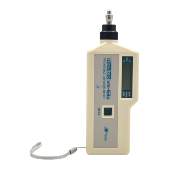
Outline Outline The VM-63A is a vibration meter designed for easy mea- surement of vibrations in rotational machinery or the like. Measurement is performed simply by holding the tip of the unit against the measurement object and operating one button. The unit can measure acceleration, velocity, and displacement. -
Page 12: Controls And Features
Controls and Features Controls and Features Front View Display Shows the measurement value, measurement mode, vi- bration frequency range, and battery replacement indica- tion. Vibration detector attachment Press this section against the measurement object. MEAS button Press this button to perform measurement (see page 10). -
Page 13: Top View
www.64817.com Controls and Features Top View H i g h r a n g e / l o w r a n g e s e l e c t o r A c c e l e r a t i o n / v e l o c i t y / d i s p l a c e m e n t s e l e c t o r High range/low range selector For acceleration measurement, set the vibration frequency... -
Page 14: Rear View
www.64817.com Controls and Features Rear View Battery compartment A single 9-volt battery (6F22) is inserted here. Bottom View S i g n a l o u t p u t j a c k Signal output jack The AC output signal is supplied at this jack. The signal output is 2-volt peak at full-scale point. - Page 15 Controls and Features CAUTION In case of excessive vibration, the earphone may produce a very high sound pressure level that can be harmful to the ear. Use this function with care.
-
Page 16: Preparations
Preparations Preparations Inserting the Battery 1. While pressing down the section marked PUSH, lift the battery compartment lid up to open it. L i f t u p P u s h h e r e 2. Insert one 9-volt battery (6F22), taking care to observe correct +/- polarity. -
Page 17: Measurement Preparations
Preparations Measurement Preparations 1. Make sure that a 9-volt battery (6F22) is inserted in the battery compartment. 2. Press the MEAS button. M E A S If the mark shown below ap- pears on the display, the battery M E A S b u t t o n must be replaced. - Page 18 Preparations When acceleration measurement (m/s ) has been se- lected, the vibration frequency range can be set to "Lo" (10 Hz to 1000 Hz) or "Hi" (1 kHz to 15 kHz) with the high range/low range selector.
-
Page 19: Display Functions
Display Functions Display Functions Measurement mode indicator Shows which measurement mode is currently selected. High range/low range indicator When acceleration measurement (m/s ) is selected, this indicator shows whether the vibration frequency is set to "Lo" (10 Hz to 1000 Hz) or "Hi" (1 kHz to 15 kHz). Replace battery mark When this mark is shown, the remaining battery capacity is very low. -
Page 20: Measurement
Measurement Measurement 1. While keeping the MEAS button depressed, hold the vibration detector against the measurement object. Use a pressure of about 500 g to 1 kg. If the MEAS button is pressed while power is off, the unit will require about 10 seconds until measurement is possible. - Page 21 Measurement Note • Vibrations in the range from 10 Hz to 1000 Hz can be measured either with the attachment S or the attachment L (option). • When making acceleration measurements with the "Hi" range setting, do not use the attach- ment L.
-
Page 22: Supplied Accessories
Supplied Accessories Supplied Accessories Instruction Label The unit is delivered with instruction labels in English, Chinese, and Japanese. Select the appropriate label and attach it to the unit as shown below. -
Page 23: Appendix
Appendix Appendix Vibration Conversion Chart 1 0 0 0 0 5 0 0 0 3 0 0 0 2 0 0 0 1 0 0 0 5 0 0 3 0 0 2 0 0 1 0 0 0 . 5 0 . -
Page 24: Vibration Detector Attachments
Appendix Vibration Detector Attachments The vibration detector of the VM-63A can be used with- out an attachment or with two kinds attachments, S (sup- plied) and L (option), to fit the respective measurement requirements. With attachment S A t t a c h m e n t S The unit is delivered in this con- dition. - Page 25 Contact resonance in acceleration measurement (measured with Rion FFT Signal Analyzer) W i t h o u t a t t a c h m e n t A t t a c h m e n t S...
- Page 26 Appendix W i t h o u t a t t a c h m e n t A t t a c h m e n t S - 1 0 A t t a c h m e n t L - 1 0 - 1 5 - 2 0...
-
Page 27: Specifications
Specifications Specifications Built-in accelerometer Piezoelectric accelerometer (shear-type) Measurement range Acceleration: 0.1 to 199.9 m/s peak (rms × Velocity: 0.1 to 199.9 mm/s rms Displacement: 0.001 to 1.999 mm p-p (rms × 2 Velocity and displacement range is lim- ited by acceleration 199.9 m/s Measurement accuracy (80 Hz) Acceleration: ±5% ±2 digits Measurement frequency range... - Page 28 Specifications Power supply 6F22 9 V battery × 1 Current consumption Approx. 7 mA at 9 V Battery life About 25 h continuous use (at 25ºC, with manganese battery) Auto power-off function Operates when no control is operated for 1 minute Ambient conditions -10 to +50ºC, 30 to 90% RH (no conden- sation)
- Page 29 Specifications Unit: mm Dimensional Drawings...
- Page 30 No. 31927 06-08 Printed in Japan...
Need help?
Do you have a question about the VM-63A and is the answer not in the manual?
Questions and answers