
Related Manuals for Rion VA-12


Summary of Contents for Rion VA-12
- Page 1 INSTRUCTION MANUAL VIBRATION ANALYZER VA-12 3-20-41 Higashimotomachi, Kokubunji, Tokyo 185-8533, Japan http://www.rion.co.jp/english/...
-
Page 3: General Operation
Organization of this manual This manual describes the features, operation and other aspects of the Vibration Analyzer VA-12. If the unit is used together with other equipment to confi gure a measurement system, consult the documentation of all other components as well. -
Page 4: Advanced Operation
Measurement in Time Waveform Mode Describes the display screen contents and operation steps in time waveform mode. Measurement in FFT Mode Describes the display screen contents and operation steps in FFT mode. Recording Waveform Data Describes the waveform recording function. Recalling Stored Data Describes how to recall data that were saved from the various measurement screens, and how to view recalled data. -
Page 5: Setting Commands
Using the Backlight Describes how to use the display backlight. Status Display Lists the various status indication symbols and other indicators of the unit. SD Card Describes how to use an SD card with this unit and explains the folder structure for storing data on the card. - Page 6 Note: CE requirements are met provided that a core fi lter is fi tted to every cable. OPTION INPUT Core A: E04SR130525A (SEIWA) Core B: ZCAT2035-0930 (TDK) Core C, G, H: E04SS201010 (SEIWA) Core D, E, F: ZCAT2017-0930 (TDK) Core I: ZCAT2436-1330 (TDK) Equivalent product TRIG...
- Page 7 FOR SAFETY In this manual, important safety instructions are specially marked as shown below. To prevent the risk of death or injury to persons and severe damage to the unit or peripheral equipment, make sure that all instructions are fully understood and observed.
- Page 9 WARNING Be careful around rotating machinery. • When making measurements on exposed rotating parts or power train parts of machinery, proceed with utmost care to ensure that the accelerometer or accelerometer cable do not get caught in the machine. • When making measurements on exposed rotating parts or power train parts of machinery, do not use the shoulder belt.
- Page 10 viii...
- Page 11 Precautions Operate the unit only as described in this manual. Do not touch any parts of the unit other than necessary for operation. Do not drop the unit. Protect it from shocks and vibration. The permissible ambient temperature range for operation of the unit is −10°C to +50°C.
-
Page 12: Table Of Contents
Contents FOR SAFETY .................v General Operation ............1 Outline ....................3 Block diagram ................4 Controls and Features ..............5 Front Panel ................5 Top Panel ...................8 Bottom Panel ................9 Rear Panel ................10 Preparations .................. 11 Power supply ................11 Connecting the accelerometer ..........14 Inserting the SD card ............... - Page 13 Measurement in Time Waveform Mode ......... 41 Reading the display ..............42 Changing measurement parameters .........48 Zooming/moving the display ........... 51 Performing measurement ............53 Storing measurement data ............54 Measurement in FFT Mode ............55 Reading the display ..............56 Changing measurement parameters and display parameters ..65 Zooming/moving the display ...........69 Performing measurement ............
- Page 14 Overlay Display ................110 Activating the overlay display ..........110 Canceling the overlay display ..........111 Reactivating the overlay display ..........111 Setup Files and Initialization ............112 Resume function ..............112 Loading a setup fi le at startup ..........112 Initialization ................
- Page 15 Other Information ............ 151 Specifi cations ................152 Index ................... 163 xiii...
-
Page 17: General Operation
General Operation... -
Page 19: Outline
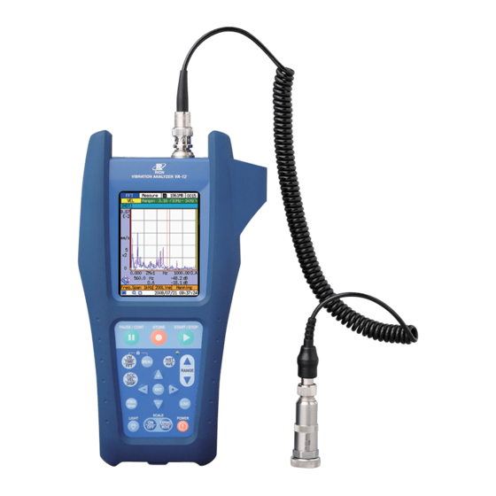
Outline The VA-12 is a portable vibration analyzer with FFT analysis function specially designed for making measurements in the field. It comes with the Piezoelectric Accelerometer PV-57I equipped with magnetic attachment. Because the VA-12 is equipped with the constant-current power supply, the accelerometers with integrated preamplifi er (CCLD type) can be connected. -
Page 20: Block Diagram
Outline • Data are stored on handy SD cards • Setup fi les allow specifying fi ve different sets of parameters • Five setup fi les can be stored as a group on an SD card • Display image can be captured as a BMP fi le •... -
Page 21: Controls And Features
Controls and Features Front Panel VA-12 VIBRATION ANALYZER (1) Display (2) START/STOP key (3) STORE key (4) PAUSE/CONT key PAUSE/CONT STORE START/STOP (19) INST/AVE key (5) MENU key (18) LED indicator (6) VM/TIME/FFT key INST TIME MENU (7) Key lock... - Page 22 Controls and Features Important Avoid operating the keys with your fi ngernail or a pointed object such as the tip of a ballpoint pen, because this can lead to faster degradation and can result in operation failure. (2) START/STOP key Serves to start and stop the measurement.
- Page 23 Controls and Features (11) LIGHT key Serves to control the display backlight. Each push of the key toggles between on and off. The backlight brightness can be set from the [System] menu. (12) SCALE ON/OFF key In time waveform mode and FFT mode, this key serves to switch the display scaling function (see page 51 and 69) on and off.
-
Page 24: Top Panel
Controls and Features Top Panel INPUT connector for accelerometer INPUT OPTION OPTION connector INPUT connector The supplied Piezoelectric Accelerometer PV-57I or another accelerometer is to be connected here. (Other supported accelerometers include PV-91C etc.) OPTION connector Serves for future expansion (currently not used). -
Page 25: Bottom Panel
Printer BL-112UI can be connected here. The port also serves for connection to a computer, using an optional USB A - Mini B cable. In this case, the SD card inserted in the VA-12 is recognized as a removable disk by the computer. -
Page 26: Rear Panel
Controls and Features Rear Panel Battery compartment Battery compartment Insert eight IEC R6 (size AA) batteries here. -
Page 27: Preparations
Preparations Power supply The unit can be powered from eight IEC R6 (size AA) batteries (alkaline or manganese), or the optional AC adapter NC-99. Inserting the batteries 1. Open the cover of the battery compartment, as shown in the illustration below. - Page 28 Preparations AC adapter To use the optional AC adapter, connect it to the unit as shown below. Bottom side of VA-12 MEMORY CARD DC IN 11-15V TRIG IN AC adapter NC-99 DC IN connector To AC outlet (90 V to 240 V AC)
- Page 29 Setting this switch to the “B” position allows the VA-12 to turned on simply by supplying power to the DC IN connector. In this case, the POWER key on the front panel of the VA-12 has no effect. Important When setting the power-on mode switch to the “B”...
-
Page 30: Connecting The Accelerometer
Preparations Connecting the accelerometer Connect the accelerometer 1. Connect the piezoelectric accelerometer as shown below. Connector ring INPUT connector Connector Magnet attachment Piezoelectric Accelerometer Curled Accelerome- VP-53S PV-57I Connector ter Cable VP-51KI Caution The magnet attachment VP-53S is extremely powerful (0.8 kG to 1 kG). - Page 31 Preparations 2. Insert the connector plug of the cable into the INPUT connector on the VA-12, and rotate the connector ring clockwise to fi rmly lock the plug. 3. If the accelerometer has been changed, use the supplied calibration chart to make the sensitivity setting (see the “Making sensor settings”...
-
Page 32: Inserting The Sd Card
Do not use SD cards other than those specifi ed by Rion, to avoid the risk of malfunction. Removing the SD card When you push the SD card a bit further in, the card... -
Page 33: Setting The Current Date/Time
Preparations Setting the current date/time 1. Turn the VA-12 on. 2. Press the MENU key to bring up the [Menu List] screen. [Menu List] screen 3. Use the keys to select [System (Language)] and press the ENT key. The [SYSTEM] menu screen is displayed. -
Page 34: Selecting The Language
Preparations 4. Use the keys to select [Time Setting] and press the ENT key. The [System/Current Time] screen appears. Use the / keys to move to the item to change, and use the keys to change the numeric value. Holding down the keys changes the value more quickly. -
Page 35: Using The Shoulder Belt
Preparations Using the shoulder belt The supplied shoulder belt can be used to support the unit during a measurement. 1. Attach the belt to the bar on the top section of the unit. 2. Wear the belt around your neck, as shown in the illustration. -
Page 36: Attaching The Sensor To The Protective Cover
Protective cover VA-12 VIBRATION ANALYZER PAUSE/CONT STORE START/STOP Note The protective cover serves to protect the unit from external shocks. -
Page 37: Connection To A Printer (Bl-112Ui)
Preparations Connection to a printer (BL-112UI) The USB port on the bottom can be used to connect the VA-12 to a printer, as shown below. The USB Mini B - B cable CC-97 is available as an option. Bottom MEMORY CARD... -
Page 38: Pv-57I Other
Menu Operation Menu structure The menus of the VA-12 are organized in a hierarchical structure. To return to the next higher level from a lower level, press the MENU key. Bold: Screen name, Regular font: Item name Can also be selected in recall mode... -
Page 39: Menu Fl Ow Diagram
Menu Operation Menu fl ow diagram A diagram of the overall menu structure is shown below. You fi rst access the menu list and then proceed to the desired menu page. To directly return to the measurement screen, press the START/STOP key. Menu screens START/STOP Returns... -
Page 40: Menu Operation
Menu Operation Menu operation Calling up a menu page 1. Press the MENU key to bring up the [Menu List] screen. 2. Use the keys to select the desired menu name ([FFT] in the example) and press the ENT key. [Menu List] screen Note The cursor will continue to move through the menu... - Page 41 Menu Operation Calling up a submenu Menu items for which a symbol is shown at right have a submenu screen. 1. Use the keys to move the cursor to the menu item for which to display the submenu ([Read/Save Setting] in the example). [SYSTEM] menu screen Note The cursor will continue to move through the menu...
- Page 42 Menu Operation Making settings from a popup list 1. Use the keys to move the cursor to the menu item to set ([High- pass Filter] in the example). 2. Press the ENT key or the key. A popup list appears. [Analog Input] menu screen 3.
- Page 43 Menu Operation Making a setting by direct edit Numeric values such as date and time or sensor sensitivity can be set by directly editing the setting. 1. Use the keys to move the cursor to the menu item to set ([Other] in the example).
-
Page 44: Analysis Functions
“FFT mode”. These can be chosen as required by the application. Vibration meter mode Select this mode to use the VA-12 as a vibration meter. Time waveform mode Select this mode to use the VA-12 for checking time waveforms. -
Page 45: Switching Between Analysis Functions
Analysis Functions Switching between analysis functions Each push of the VM/TIME/FFT key cycles the unit through the following settings: vibration meter mode time waveform mode FFT mode (graph display) FFT mode (list display) vibration meter mode ... (solid ar- rows in the illustration below) Vibration meter mode Time waveform mode (See pages 31 to 40) - Page 46 Analysis Functions To access the time waveform mode and FFT mode (list display), proceed as follows. • To display the time waveform mode Call up the [Display] menu and set [Time Level] to [On]. • To display the FFT mode (list display) Call up the [Display] menu and set [Level List] to [On].
-
Page 47: Measurement In Vibration Meter Mode
Measurement in Vibration Meter Mode Before starting a measurement, be sure to set the clock of the unit to the correct date/time (see pages 17 to 18). This section contains the minimum instructions for measurement in vibration meter mode. The following items are explained. •... -
Page 48: Reading The Display
Measurement in Vibration Meter Mode Reading the display Measurement parameter items Analysis function Input range Measurement High-pass filter data type Low-pass filter Operation status indicator Over Bar graph Analysis function Shows “VM”. The function can be switched with the VM/TIME/FFT key. - Page 49 Measurement in Vibration Meter Mode High-pass fi lter The high-pass fi lter value set from the [Analog Input] menu screen is shown here. The following settings are available: 1 Hz, 3 Hz, 10 Hz, 1 kHz Low-pass fi lter The low-pass fi lter value set from the [Analog Input] menu screen is shown here.
- Page 50 Measurement in Vibration Meter Mode Display parameter items Measurement status Store address Overload Over indication Vibration meter scale Bar graph upper/lower limit values Acceleration rms Measurement value indication value indica- Acceleration peak tion value indication Acceleration crest factor indication Velocity rms value indication Displacement equivalent p-p...
- Page 51 Measurement in Vibration Meter Mode Measurement value indication Five measurement values are shown simultaneously and are updated every second. When momentary overload has occurred, the respective measurement value indication is highlighted in red. Displacement equivalent p-p value indication The equivalent p-p value for displacement (rms value × 2 √2 ) is shown here as a numeric indication.
- Page 52 Measurement in Vibration Meter Mode Other items SD card inserted symbol SD card remaining capacity Power supply status Current date/time indicator Key lock symbol SD card remaining capacity When an SD card is inserted, the remaining capacity is shown here. Current date/time The current date and time are shown here.
-
Page 53: Changing Measurement Parameters And Display Parameters
Measurement in Vibration Meter Mode Changing measurement parameters and display parameters The measurement parameters and display parameters in vibration meter mode are as follows. Menu Key operation page Sensor information Analog Input 15, 38 High-pass fi lter Analog Input Low-pass fi lter Analog Input Input range RANGE... - Page 54 Measurement in Vibration Meter Mode Making sensor settings Use the supplied calibration chart of the accelerometer you intend to use, and make the sensitivity setting by performing the following steps. 1. From the [Analog Input] menu screen, select [Sensor Selection] and then [PV-57I] or [Other].
-
Page 55: Performing Measurement
Measurement in Vibration Meter Mode Performing measurement The measurement will start automatically when the vibration meter mode measurement screen is brought up. The following values are measured simultaneously and updated in 1-second intervals. • Acceleration rms value (m/s • Acceleration peak value (m/s •... -
Page 56: Storing Measurement Data
Measurement in Vibration Meter Mode Storing measurement data You can store measurement data on an SD card inserted in the unit. When using the time trigger function to store data, refer to the “Trigger Functions” section. 1. Verify that the SD card symbol is shown on the title bar. -
Page 57: Measurement In Time Waveform Mode
Measurement in Time Waveform Mode Before starting a measurement, be sure to set the clock of the unit to the correct date/time (see pages 17 to 18). This section contains basic instructions for measurement in time waveform mode. The following items are explained. •... -
Page 58: Reading The Display
Measurement in Time Waveform Mode Reading the display Measurement parameter items Analysis function High-pass filter Input range Low-pass filter Measurement data type Operation status indicator Frequency span Number of analysis lines Analysis function Shows “TIME”. The function can be switched with the VM/TIME/FFT key. - Page 59 Measurement in Time Waveform Mode Low-pass fi lter The low-pass fi lter value set from the [Analog Input] menu screen is shown here. The following settings are available: 1 kHz, 5 kHz, 20 kHz Number of analysis lines Shows the setting made with the LINE key. The following settings are available.
- Page 60 Measurement in Time Waveform Mode Display parameter items Measurement status Store address Y axis upper limit Scroll bar Y axis unit Cursor Cursor value readout X axis zoom factor Y axis lower limit X axis unit X axis lower limit X axis upper limit Graph zoom symbol...
- Page 61 Measurement in Time Waveform Mode X axis zoom factor Shows the X axis zoom factor for the currently displayed graph. The following settings are available. • Number of analysis lines is 3200: ×1, ×2, ×4, ×8, ×16, ×32 • Number of analysis lines is 1600: ×1, ×2, ×4, ×8, ×16 •...
- Page 62 Measurement in Time Waveform Mode Cursor value readout This shows the value at the marker symbol on the cursor. The left value is for the X axis and the right value for the Y axis. Cursor The cursor can be moved right and left with the / keys. Holding down a key will move the cursor faster.
- Page 63 Measurement in Time Waveform Mode Other items SD card inserted symbol SD card remaining capacity Power supply status Current date/time indicator Key lock symbol SD card remaining capacity When an SD card is inserted, the remaining capacity is shown here. Current date/time The current date and time are shown here.
-
Page 64: Changing Measurement Parameters
Measurement in Time Waveform Mode Changing measurement parameters The measurement parameters in time waveform mode are as follows. Menu Key operation page Sensor information Analog Input 15, 49 High-pass fi lter Analog Input Low-pass fi lter Analog Input Measurement data type ACC/VEL/DISP Input range RANGE... - Page 65 Measurement in Time Waveform Mode Making sensor settings Use the supplied calibration chart of the accelerometer you intend to use, and make the sensitivity setting by performing the following steps. 1. From the [Analog Input] menu screen, select [Sensor Selection] and then [PV-57I] or [Other].
- Page 66 Measurement in Time Waveform Mode Specifying the store name To store measurement data, it is necessary to fi rst specify a store name. Access the [Measure] menu and select [Store Name]. Measurement data will be stored in a folder of the specifi ed name. (See the “SD Card”...
-
Page 67: Zooming/Moving The Display
Measurement in Time Waveform Mode Zooming/moving the display To expand or shrink the display, proceed as follows. 1. Enable the display scaling/zoom mode (graph zoom symbol shown at bottom left of graph) (see illustration below). If the magnifying glass symbol is shown, the unit is in display scaling mode. - Page 68 Measurement in Time Waveform Mode Functions of keys differ, according to display mode Key operation Display mode Symbol Cursor Increment Decrement Overall data Solid Move cursor Move cursor None store store display line left * right * address (+) address (−) Display scaling/ Broken Shrink X...
-
Page 69: Performing Measurement
Measurement in Time Waveform Mode Y axis zoom factor In time waveform mode, the Y axis zoom factor is not shown. The zoom factor can be calculated according to the following equation. Y axis zoom factor = input range / Y axis upper limit Note The Y axis zoom factor is 2 (n = 0 to 14), but because... -
Page 70: Storing Measurement Data
Measurement in Time Waveform Mode Storing measurement data You can store measurement data on an SD card inserted in the unit. When the trigger function is enabled, refer to the “Trigger Functions” section. 1. Verify that the SD card symbol is shown on the title bar. -
Page 71: Measurement In Fft Mode
Measurement in FFT Mode Before starting a measurement, be sure to set the clock of the unit to the correct date/time (see pages 17 to 18). This section contains basic instructions for measurement in FFT mode. The following items are explained. •... -
Page 72: Reading The Display
Measurement in FFT Mode Reading the display Graph display (measurement parameter items) Analysis function High-pass filter Input range Low-pass filter Measurement data type Operation type Waveform recording in progress indicator Current averaging count /Average number indication Operation status indicators Frequency span Waveform recording Number of Window function... - Page 73 Measurement in FFT Mode The following settings are available: High-pass fi lter: 1 Hz, 3 Hz, 10 Hz, 1 kHz Low-pass fi lter: 1 kHz, 5 kHz, 20 kHz Waveform recording in progress indicator When the waveform recording function has been set to [ON], this indicator fl ashes during processing.
- Page 74 Measurement in FFT Mode Operation status indicator If the repeat trigger or single trigger is enabled, TRG is shown • here. If the time trigger is enabled, TIME is shown. The trigger settings are made from the [Measure] menu screen. For details, see the “Trigger Functions”...
- Page 75 Measurement in FFT Mode Graph display (display parameter items) Measurement status Store address Y axis upper limit Scroll bar Y axis unit Overall value Cursor bar graph Y axis zoom factor Cursor value readout and unit X axis zoom factor X axis unit Y axis lower limit X axis upper limit...
- Page 76 Measurement in FFT Mode X axis zoom factor Shows the X axis zoom factor for the currently displayed graph. The following settings are available. • Number of analysis lines is 3200: ×1, ×2, ×4, ×8, ×16 • Number of analysis lines is 1600: ×1, ×2, ×4, ×8 •...
- Page 77 Measurement in FFT Mode X axis lower limit Shows the lower limit value of the X axis for the current display range. Y axis lower limit Shows the lower limit value of the Y axis for the current display range. Cursor value readout and unit This shows the value at the marker symbol on the cursor.
- Page 78 Measurement in FFT Mode Y axis unit If FFT scale is [Log], the indication [dB] is shown here. • Acceleration: Referenced to 1 m/s • Velocity: Referenced to 1 mm/s • Displacement: Referenced to 1 mm • Envelope: Referenced to 1 If FFT scale is [Linear], the unit indication changes according to the measurement data type.
- Page 79 Measurement in FFT Mode Graph display (Other items) SD card inserted symbol SD card remaining capacity Power supply status Current date/time indicator Key lock symbol SD card remaining capacity When an SD card is inserted, the remaining capacity is shown here. Current date/time The current date and time are shown here.
- Page 80 Measurement in FFT Mode List display Store address keys to change Cursor / keys to move cursor Pressing the VM/TIME/FFT key in graph display mode switches to list display. The ten highest level values out of the data range covered by the graph display are listed, in descending order.
-
Page 81: Changing Measurement Parameters And Display Parameters
Measurement in FFT Mode Changing measurement parameters and display parameters The measurement parameters and display parameters in FFT mode are as follows. Menu Key operation page Sensor information Analog Input 15, 65 High-pass fi lter Analog Input Low-pass fi lter Analog Input Measurement data type ACC/VEL/DISP... - Page 82 Measurement in FFT Mode Changing the input range Set the input range to an optimum setting. Over or Over ) appears on the left side of If the overload indication ( display, the input range setting is too low. Use the RANGE key to increase the setting (see left illustration below).
- Page 83 Measurement in FFT Mode Selecting the operation type Make the setting with the [Operation Type] item in the [FFT] menu. • LIN: Linear average • EXP: Exponential average • MAX: Maximum hold Note Instantaneous value cannot be selected from the [FFT] menu.
- Page 84 Measurement in FFT Mode Setting the FFT scale type Make the setting for the FFT scale (Y axis scale) with the [FFT Scale] item in the [Display] menu. • Log: Logarithmic scale • Linear: Linear scale Setting the cursor X axis unit 1.
-
Page 85: Zooming/Moving The Display
Measurement in FFT Mode Zooming/moving the display To expand or shrink the display, proceed as follows. 1. Enable the display scaling/zoom mode (graph zoom symbol shown at bottom left of graph) (see illustration below). If the magnifying glass symbol is shown, the unit is in display scaling mode. - Page 86 Measurement in FFT Mode Functions of keys differ, according to display mode Key operation Display mode Symbol Cursor Increment Decrement Overall data Solid Move cursor Move cursor None store store display line left * right * address (+) address (−) Display scaling/ Broken Shrink X...
-
Page 87: Performing Measurement
Measurement in FFT Mode Performing measurement The operation principles for measurement in FFT mode are explained in this section. For information on measurement using the trigger functions, see the “Trigger Functions” section. Operation type overview The chart below shows an outline of the various operation types. START/STOP START/STOP START/STOP... - Page 88 0.04 sec 0.08 sec 0.16 sec Note 1 The FFT calculation interval is a value specifi c to the VA-12. Note 2 The time required until the fi rst FFT processing results is displayed is equal to the frame time.
- Page 89 Measurement in FFT Mode Performing instantaneous value measurement 1. Make the required measurement parameter and display parameter settings using the [FFT] menu, [Measure] menu, etc. (see page 65). 2. Repeatedly press the VM/TIME/FFT key to bring up the FFT mode screen.
- Page 90 Measurement in FFT Mode Performing linear averaging or maximum hold measurement 1. Make the required measurement parameter and display parameter settings using the [FFT] menu, [Measure] menu, etc. (see page 65). Set [Operation Type] in the [FFT] menu to [LIN] or [MAX]. 2.
-
Page 91: Storing Measurement Data
Measurement in FFT Mode Storing measurement data You can store measurement data on an SD card inserted in the unit. When the trigger function is enabled, refer to the “Trigger Functions” section. Important While the LED indicator is fl ashing, do not turn off power to the unit or remove the SD card. - Page 92 Measurement in FFT Mode 2. Check the store address shown at the right end of the title bar. • If the address is shown on a white background: Proceed to step 3. • If the address is shown on a red background: This indicates that the store address already contains measurement data.
-
Page 93: Recording Waveform Data
Recording Waveform Data The VA-12 can record waveform data in fi les of up to 1 MB per recording operation. The recorded waveform information is stored as a RIFF format WAVE fi le along with the FFT store data on the SD card. -
Page 94: Re-Analyzing Waveform Data
In the WAVE file, the waveform data of the two sections will be joined. Re-analyzing waveform data The optional waveform analysis software AS-70 or CAT-WAVE can be used to re-analyze the waveform data. Re-analyzing on the VA-12 itself is not possible. -
Page 95: Recalling Stored Data
Recalling Stored Data Procedure for recalling stored data 1. Press the MENU key to display the [Menu List] screen. 2. Use the keys to select [Recall] and press the ENT key. 3. The [Recall/Select File] screen is shown. Use the keys to select the store name and press the ENT key. - Page 96 Recalling Stored Data 4. The lower part of the [Recall/Select File] screen changes into a [Recall Address] menu which specifi es the address number, as shown below. Use the keys to increase or decrease the address number. When the correct address is shown, press the ENT key. Only addresses that actually contain saved data can be selected.
- Page 97 Recalling Stored Data 5. The data in the folder with the store name specifi ed in step 3 and the store address specifi ed in step 4 are displayed. For an explanation of the recall screen, see the next page. Important It may take several seconds for the data to appear.
-
Page 98: Reading The Recall Screen
Recalling Stored Data Reading the recall screen This section explains peculiar items of the recall screen. Measurement status Store address Overall value bar graph Trigger start time or processing completion time Recall screen (in FFT mode) Measurement status Shows “Recall”. Store address Shows the address whose data are currently displayed. -
Page 99: Changing The Display
Recalling Stored Data Changing the display The procedure is in principle the same as for the measurement screen. However, the VM/TIME/FFT key functions as follows. Vibration meter mode: Key has no effect Time waveform mode: Key has no effect FFT mode: Toggles between graph display and list display The steps for changing the display according to the analysis function are as listed below. -
Page 100: Deleting Stored Data
Recalling Stored Data Deleting stored data You can delete stored data from the SD card using the VA-12. Note When using the VA-12, only complete folders indicated by specifying the store name can be deleted (see illustration below). To delete data in a specifi c store address only, you must use a computer as described in the “SD Card”... -
Page 101: Saving The Screen As A Bmp File
Saving the Screen as a BMP File The VA-12 allows storing the current screen image as a BMP fi le in a specifi ed folder on the SD card. Saving the measurement screen or recall screen 1. Display the measurement screen or recall screen. -
Page 102: Displaying A Bmp Fi Le
Saving the Screen as a BMP File Displaying a BMP fi le Stored BMP fi les can be viewed on a computer. For information on the data storage location, see the “SD Card” section. -
Page 103: Printing
Printing Connecting the Printer BL-112UI to the VA-12 (see page 21) allows printout of the measurement screen and recall screen. Printing the measurement screen 1. Display the measurement screen. 2. Press the MENU key. 3. Use the keys to select [Print] and press the ENT key. -
Page 104: Printing Stored Data Continuously
Printing Printing stored data continuously For data stored in vibration meter mode and FFT mode, it is possible to specify a range from the data list and print the specifi ed range continuously. 1. Recall the stored data to be printed. (See the “Recalling Stored Data” section.) 2. -
Page 105: Advanced Operation
Advanced Operation... -
Page 107: Trigger Functions
Trigger Functions The trigger functions of the VA-12 can be used for each analysis mode except for FFT mode (instantaneous value). Four types of trigger operation modes are available: [Free], [Repeat], [Single], [Time]. In vibration meter mode, only [Free] and [Time] are available. - Page 108 Trigger Functions Single Processing is only carried out once, at the fi rst trigger occurrence. However, in FFT mode (exponential averaging), processing continues from the fi rst trigger occurrence until the START/STOP key is pressed. Trigger Trigger START/STOP key Measurement mode Time waveform FFT (EXP) FFT (LIN, MAX)
-
Page 109: Making Trigger Settings
Pretrigger is disabled. Pretrigger is enabled. Note The VA-12 does not have a post trigger function. 5. When the [Trigger Source] has been set to [Level], the [Trigger Level] and [Slope] items must be set. (See “Level trigger” section below.) Level trigger When the input level reaches the trigger level, processing starts. - Page 110 Trigger Functions Start (FS 5/8, Slope + setting) Start (FS 5/8, Slope − setting) Trigger level Trigger level −2/8 Start (FS −2/8, Slope + setting) Start (FS −2/8, Slope − setting) External trigger Processing starts when an external signal is input. When the falling edge of a TTL level signal (minimum pulse 10 µs) is detected, or when the input is shorted, triggering occurs.
- Page 111 Trigger Functions Making time trigger settings 1. From the [Measure] menu screen, select [Store Name]. The measurement data will be stored in the folder specifi ed by the [Store Name] item. (For details, see the “SD Card” section.) 2. Set the [Trigger Mode] to [Time]. 3.
- Page 112 Trigger Functions Max. averaging Frequency Number Frame Overlap 1 min. 5 min. 10 min. 30 min. 60 min. span(Hz) of lines time(s) ratio * (60 sec) (300 sec) (600 sec) (1800 sec) (3600 sec) 1000 2048 2048 2048 2048 1000 1489 2048 2048...
-
Page 113: Performing Measurement With Repeat Trigger
Trigger Functions Performing measurement with repeat trigger Time waveform mode The operation principle when using time waveform mode is illustrated below. 1 frame end 1 frame end 1 frame end Trigger Trigger Trigger START/STOP START/STOP key pressed key pressed Waveform data Waveform data Waveform data for 1 frame... - Page 114 Trigger Functions FFT mode (exponential averaging) The operation principle when using FFT mode (exponential averaging) is illustrated below. 1 frame end 1 frame end 1 frame end Trigger Trigger Trigger START/STOP START/STOP key pressed key pressed Exponential Exponential Exponential averaging averaging averaging Trigger...
- Page 115 Trigger Functions FFT mode (linear averaging, maximum hold) The operation principle when using FFT mode (linear averaging, maximum hold) is illustrated below. Trigger START/STOP Trigger key pressed Frame 2 Frame 1 Frame N average average average Trigger Frame 1 end Frame 2 end Frame N end disabled...
- Page 116 Note If the START/STOP key is pressed before averaging processing is completed, the trigger operation is terminated. The VA-12 shows the averaged data calculated up to that point. If there was no trigger occurrence, no averaged data will be displayed when trigger operation is terminated.
-
Page 117: Performing Measurement With Single Trigger
Trigger Functions Performing measurement with single trigger Time waveform mode The operation principle when using time waveform mode is illustrated below. Trigger 1 frame end Trigger 1 frame end START/STOP START/STOP START/STOP key pressed key pressed key pressed Waveform data Waveform data for 1 frame for 1 frame... - Page 118 Trigger Functions FFT mode (exponential averaging) The operation principle when using FFT mode (exponential averaging) is illustrated below. START/STOP START/STOP key pressed key pressed Trigger Trigger START/STOP START/STOP key pressed key pressed Processing Processing Trigger Trigger Screen standby standby display Hold Clear Update...
- Page 119 Trigger Functions FFT mode (linear averaging, maximum hold) The operation principle when using FFT mode (linear averaging, maximum hold) is illustrated below. 1 frame end 1 frame end Trigger Trigger START/STOP START/STOP key pressed key pressed Frame 1 to N Frame 1 to N processing processing...
-
Page 120: Performing Measurement With Time Trigger
Operation when START/STOP key is pressed The operation when the START/STOP key is pressed is as follows. If the VA-12 is in vibration meter mode or time waveform mode, the pressing the key has no effect. If the VA-12 is in FFT mode, the following applies: •... - Page 121 Trigger Functions Vibration meter mode The operation principle when using vibration meter mode is illustrated below. S: Preset store count Trigger start time Store action S No store Store Store Store action STORE key pressed action 1 action 2 action 3 Time Store Store...
- Page 122 Trigger Functions Time waveform mode The operation principle when using time waveform mode is illustrated below. S: Preset store number Trigger start time Store action S No store Store Store Store action STORE key pressed action 1 action 2 action 3 Time Store Store...
- Page 123 Trigger Functions FFT mode (exponential averaging) The operation principle when using FFT mode (exponential averaging) is illustrated below. Trigger Trigger Time trigger Trigger STORE key event S-1 event S start time event 2 pressed Time Store Store S: Preset store standby interval interval...
- Page 124 Trigger Functions Note If the waveform recording function is set to [On], waveform data will also be stored at this point. During processing, the waveform recording in progress indicator is fl ashing in the top section of the graph. For details on the waveform recording function, see the “Recording Waveform Data”...
- Page 125 Trigger Functions 2. Press the STORE key. The “Waiting for Time Trigger...” popup indication appears, the symbol is fl ashing, and the LED indicator is fl ashing in yellow. Note The trigger operation cannot be paused. 3. When the trigger start time is reached, the popup indication “START” appears, and the data averaged up to this point are stored.
-
Page 126: Overlay Display
Overlay Display In FFT mode (graph display), the screen for displaying stored data can be shown together with the current measurement screen in an overlay confi guration. This makes comparison of data easier. Activating the overlay display 1. At the [Display] menu screen, set the [Overlapping] item to [On]. 2. -
Page 127: Canceling The Overlay Display
Overlay Display Note If stored data are not shown, set the [Overlapping] item in the [Display] menu screen to [On]. Overlay display is only possible if the following measurement parameters are identical for the recalled data and measurement data: analysis mode, measurement data type, frequency span, number of analysis lines. -
Page 128: Setup Files And Initialization
Loading a setup fi le at startup When power to the VA-12 is turned on while an SD card is present, containing one or more setup fi les (special type of fi le in a specifi ed folder: SETUP folder of folder structure on page 126), a dialog window asking the user whether to load stored settings appears. -
Page 129: Initialization
SD card The VA-12 allows you to store up to fi ve different sets of settings (see section starting on next page). By using SD cards, you can create multiple groups of setup fi les stored in separate folders (see illustration below and explanation on page 126). - Page 130 ENT key. The [System/Setting] screen comes up. 2. Select the desired number and press the STORE key. The current settings of the VA-12 are saved in the selected number. Note The recall screen settings are not saved. Only the settings of the immediately preceding measurement screen will be saved.
- Page 131 Setup Files and Initialization Saving settings on SD card as a group To save fi ve sets of settings (setup fi les) of the VA-12 as a group on an SD card, proceed as follows. 1. At the [SYSTEM] menu screen, select [Read/Save Setting] and press the ENT key.
-
Page 132: Pickup Sensitivity Magnify, P1
Setup Files and Initialization Setup fi le content example A setup fi le contains a list of setting commands and setting values. The fi le is a CSV (Comma Separated Values) format text fi le. An example is shown below. Setting Comma item... -
Page 133: Level Range
Setup Files and Initialization Setting items Setting items that are covered by the resume and initialization functions along with their default values are listed in the table below. *: Items stored in setup fi les Setting item Setting command Default value Backlight brightness Brightness Dark... - Page 134 Setup Files and Initialization Setting item Setting command Default value Vibration meter graph X axis Scale VM Linear scale * FFT graph Y axis scale Scale Unit FFT Y Linear * FFT cursor X axis unit Cursor Unit FFT X * FFT cursor Y axis unit Cursor Unit FFT Y Linear...
-
Page 135: Power Supply
Power Supply Battery powered operation and external power supply operation The VA-12 can be powered by batteries or an external power supply (AC adapter) connected to the unit. When both types of power sources are present, the external power supply has priority. -
Page 136: External Power Supply (Ac Adapter)
While the battery capacity symbol is the display backlight will not turn on. External power supply (AC adapter) To power the VA-12 from an external source, be sure to use the optional AC adapter NC-99. Important Do not use an adapter other than the NC-99 to prevent the risk of damage. -
Page 137: Using The Backlight
Using the Backlight The VA-12 is equipped with a display backlight that enables easy measurement also in dark locations. To use the backlight, proceed as follows. Selecting the backlight brightness 1. At the [SYSTEM] menu screen, select [Backlight Brightness]. 2. Select [Dark] or [Bright]. -
Page 138: Status Display
Status Display Symbol List The following symbols may appear on the display of the VA-12. Symbol Color Name Location Meaning Remaining battery Blue Status bar capacity (1) Remaining battery Battery powered operation Blue Status bar capacity (2) possible Remaining battery... -
Page 139: Repeat Trigger
Status Display LED Indicator Lighting patterns for status indication Status Status Color Pattern symbol Yellow Startup Green Light Blue Blue Purple Processing Green Flashing Pause Blue Flashing Overload Single trigger Yellow Sequence of 2 fl ashes standby Repeat trigger Yellow Sequence of 2 fl ashes standby Time trigger... -
Page 140: Sd Card Data Capacity
SD card. If the SD card is removed while power is on, data may be lost. SD card data capacity SD cards with a capacity of up to 2 GB can be used in the VA-12. Formatting an SD card Note When an SD card is formatted (initialized), all data present on the card will be lost. -
Page 141: Data Transfer
In that case, select FAT, FAT12, FAT16, or FAT32 as fi le system. Data transfer To transfer data stored by the VA-12 on SD card to a computer, the following two methods can be used. •... -
Page 142: Folder Structure
SD Card Folder structure The diagram below illustrates the data folder structure on the SD card. Use this as reference when accessing data on a computer or when deleting specifi c folders and fi les. VA-12 SETUP SET_0000 VA12SET1.RNS VA12SET2.RNS Setup files VA12SET3.RNS... -
Page 143: Data File Structure
SD card. The following four types of fi les are used. • Vibration meter data store fi le This type of fi le is stored when the VA-12 is in vibration meter mode. • Waveform data store fi le This type of fi le is stored when the VA-12 is in time waveform mode. -
Page 144: Data Store Fi Les
FFT data store fi les is as follows. (“ ” indicates a space.) Root block Sub block Block member Remarks [Setting] Common to all fi les [VA-12] Analysis Mode Data Type Overload Current (Skipped) Store Address Store Number Store Interval... - Page 145 Bytes Description Indicates beginning Block label (None) [Setting] of [Setting] block. Indicates beginning Block label (None) [VA-12] of [VA-12] block. VM, TIME, FFT, Analysis mode Analysis Mode 2 to 4 LIST Acceleration, Measurement data Velocity, Data Type 8 to 13...
-
Page 146: Level Trigger External Trigger
Data File Structure Item Header string Bytes Content Bytes Description Number of analysis 20 0, 40 0, 80 0, Analysis Line 3 to 4 line 1600, 3200 Average display Average Disp Lp, Ave 2 to 3 Operation type Average Type Linear, Exp, Max Average number Average Count... - Page 147 Data File Structure Data section (vibration meter data store fi le) In the case of a vibration meter data store fi le, the data section has the fol- lowing content. Header Item Bytes Content Bytes string Block label (None) [Data] xxxx.y, zzzzzzz Acceleration rms value •...
- Page 148 Data File Structure Data section (FFT data store fi le) In the case of an FFT data store fi le, the data section has the following con- tent. Item Header string Bytes Content Bytes Block label (None) [Data] Title Frequency INST, LIN, EXP, MAX xxxxxx, yyyyyyy Frequency *...
- Page 149 Data File Structure WAVE fi les This section explains WAVE fi les. File name: WAV_(store address).WAV File format: RIFF File structure WAVE fi les employ a format called RIFF which encodes information in multiple chunks that are linked and saved as a fi le. Identifi er: “RIFF”...
- Page 150 Data File Structure The chunk confi guration used by the VA-12 is as follows. RIFF chunk: This is always located at the beginning of the WAVE fi le and is called the RIFFHeader. This chunk comprises the following fi ve sub chunk types.
- Page 151 Bytes Type Content chunkID char “data” chunkSize DWORD Waveform data size (number of bytes) DATA Constituent Waveform data WAVE fi le data of VA-12 are fi xed to 16 bit. sample1 sample2 sample3 sample4 ..Data Data Data Data ..
- Page 152 Data File Structure Contents of RIONFORMAT (“ ” indicates a space) Order Variable name Bytes Type Content nMaker DWORD Manufacturer name: “RION” ProductType char Model: “VA-12 ” DWORD Device ID: 0 nFileVersion DWORD File version: 1 or more nCpuVersion char CPU version: x.x.xxx...
- Page 153 Data File Structure Order Variable name Bytes Type Content High-pass fi lter dwCh1HighPassFilter DWORD 0: OFF, 11: 1 Hz, 12: 3 Hz, 15: 10 Hz, 50: 1 kHz Reserved DWORD Reserved DWORD Reserved DWORD Trigger type dwTriggerType DWORD 0: Free, 10: Level, 20: Time, 30: Ext. Trigger mode dwTriggerMode DWORD...
- Page 154 Reserved WORD Used to delimit header section at 512 dummy Undetermined bytes * Example for 1/8: 1 / 8 = 12.5% memo sub chunk (fi xed to 40 kB, VA-12 specifi c) Variable name Bytes Type Content chunkID char “memo”...
-
Page 155: Setting Commands
Setting Commands Setting commands are text strings that represent measurement or display parameters etc. of the VA-12. Setting commands are used in setup fi les and data store fi les. Setting command format Setting command = “command name” + “,” + “parameter” + [CRLF] The basic components of a setting command are the command name and the parameter. -
Page 156: Command List
Setting Commands Command List System Command Function Page Beep Beep ..........142 Status Command Function Page Analysis Mode Analysis mode ......... 142 Data Type Measurement data type ....142 Measurement parameters Command Function Page High Pass Filter High-pass fi lter ......... 142 Low Pass Filter Low-pass fi lter ........ -
Page 157: Function
Setting Commands Axis/zoom settings Command Function Page FFT Expand X FFT X axis zoom ......146 FFT Expand Y Log FFT Y axis zoom (Log) ..... 146 FFT Expand Y LIN FFT Y axis zoom (Lin) .......147 TIME Expand X Time X axis zoom ......147 TIME Expand Y Time Y axis zoom ......147... -
Page 158: Parameter
Setting Commands Command Description System Beep setting command Beep, p1 Parameter Content p1 = “Off” Beep off p1 = “On” Beep on Status Analysis mode setting command Analysis Mode, p1 Parameter Content p1 = “VM” Vibration meter p1 = “TIME” Time waveform p1 = “FFT”... - Page 159 Setting Commands Low-pass fi lter setting command Low Pass Filter, p1 Parameter Content p1 = “1kHz” 1 kHz p1 = “5kHz” 5 kHz p1 = “20kHz” 20 kHz Input range setting command Level Range, p1 Parameter Content p1 = “0” to “6” An actual value is different according to the setting.
- Page 160 Setting Commands Average display setting command Average Disp, p1 Parameter Content p1 = “Lp” Instantaneous value p1 = “Ave” Average Operation type setting command Average Type, p1 Parameter Content p1 = “Linear” Linear average p1 = “Exp” Exponential average p1 = “Max” Maximum hold Average number setting command Average Count, p1...
-
Page 161: P1 = "Level Trigger
Setting Commands Accelerometer sensitivity (factor) setting command Pickup Sensitivity Magnify, p1 Parameter Content p1 = “x0.1” ×0.1 p1 = “x0.01” ×0.01 p1 = “x0.001” ×0.001 Sensor selection setting command Sensor Type, p1 Parameter Content p1 = “PV-57I” PV-57I p1 = “Other” Other Trigger Trigger mode setting command... - Page 162 Setting Commands Trigger slope setting command Trigger Slope, p1 Parameter Content p1 = “−” Slope − p1 = “+” Slope + Pretrigger setting command Pretrigger, p1 Parameter Content p1 = “None” p1 = “Pretrigger” Axis/zoom settings FFT X axis zoom setting command FFT Expand X, p1 Parameter Content...
-
Page 163: Parameter P1 = −7 To
Setting Commands FFT Y axis zoom (Lin) setting command FFT Expand Y LIN, p1 Parameter Content p1 = 0 to 10 to 2 Time X axis zoom setting command TIME Expand X, p1 Parameter Content p1 = “x1” ×1 p1 = “x2” ×2 p1 = “x4”... - Page 164 Setting Commands Display VM graph X axis scale setting command Scale VM, p1 Parameter Content p1 = “Log” Logarithmic scale p1 = “Linear” Linear scale FFT graph Y axis scale setting command Scale Unit FFT Y, p1 Parameter Content p1 = “Log” Logarithmic scale p1 = “Linear”...
- Page 165 Setting Commands Time display setting command Time Display, p1 Parameter Content p1 = “Off” p1 = “On” Display scaling mode setting command Zoom Mode, p1 Parameter Content p1 = “Off” p1 = “On” Zoom/Move mode setting command Zoom Move, p1 Parameter Content p1 = “Zoom”...
- Page 166 Setting Commands Memory Store name setting command Store Name, p1 Parameter Content p1 = 0000 to 9999 MAN_0000 to MAN_9999 Store number setting command Store Number, p1 Parameter Content p1 = 1 to 1000 Store interval setting command Store Interval, p1 Parameter Content p1 = “1min”...
- Page 167 Other Information...
- Page 168 Specifi cations Standard compliance CE marking CE requirements are met provided that a core fi lter is fi tted to every cable Chinese RoHS (export model for China only) WEEE Directive Piezoelectric accelerometer PV-57I (supplied accessory) Accelerometer type Shear-type piezoelectric accelerometer (CCLD type) Sensitivity Listed on supplied calibration chart of PV-57I.
- Page 169 Specifi cations Input range At sensitivity 0.100 mV/(m/s ) to 0.999 mV/(m/s Acceleration: 10 , 31.6 , 100 , 316 , 1000 , 3160 , 10000 (m/s ) (rms) Velocity: 31.6, 100, 316, 1000, 3160, 10000, 31600 (mm/s) (rms) Displacement: 0.89, 2.83, 8.94, 28.3, 89.4, 283, 894 (mm) (EQp-p) Using PV-57I, or at sensitivity 1.00 mV/(m/s...
-
Page 170: High-Pass Fi Lter
Specifi cations Measurement frequency range (electrical characteristics) Acceleration: 1 Hz to 20 kHz Velocity: 3 Hz to 3 kHz Displacement: 3 Hz to 500 Hz Acceleration envelope curve: 1 kHz to 20 kHz Filters Prefi lters High-pass fi lter: 1 Hz*, 3 Hz, 10 Hz, 1 kHz (−10% point) Cutoff slope −18 dB/oct, * 1 Hz for acceleration only Low-pass fi lter:... -
Page 171: Time Window Function
Specifi cations Measurement data type: The following items are calculated simultaneously (by digital processing) Acceleration (m/s rms value, peak value, crest factor Velocity (mm/s): rms value Displacement (mm): EQp-p value (rms value × 2 2 ) rms time constant: 1 second Peak value, crest factor: updated every second Time waveform mode (waveform of acceleration, velocity, displacement... -
Page 172: Trigger Mode
SD card in WAVE fi le format (max. 1 MB per fi le). (FFT analysis using WAVE fi les cannot be performed on VA-12.) Recording time examples: 10 seconds at 20 kHz frequency span, 2000 seconds at 100 Hz frequency span... - Page 173 Specifi cations Data display content Vibration meter mode: Acceleration, velocity, displacement, acceleration peak value, acceleration crest factor Acceleration, velocity, or displacement bar graph FFT mode: Spectrum graph display or list display Graph display: X axis: Entire spectrum data are represented by 201 display points, overall value excluding DC components indicated by bar graph Zoom function allows expansion of display...
- Page 174 SD card and loaded back into the unit. Swapping the current settings for saved settings and vice versa is possible. Recall function Measurement data can be read from SD card and redisplayed on screen. FFT analysis of stored time waveform data on the VA-12 is not supported.
- Page 175 Specifi cations Startup functions Resume function Settings are memorized when power is turned off and restored at next power-on Loading setup fi les at startup A specifi c fi le of settings stored on SD card can be loaded automatically at startup Input/output section USB port ×1 (Mini B)
- Page 176 Specifi cations Dimensions Without protective cover 214 mm (216 mm with BNC connector) (H) × 105 mm (W) × 36 mm (D) With protective cover 238 mm (H) × 131 mm (W) × 44 mm (D) Mass Approx. 850 g (incl. batteries, with protective cover, PV-57I connected) Supplied accessories Piezoelectric Accelerometer...
- Page 177 Specifi cations Front VA-12 VIBRATION ANALYZER PAUSE/CONT STORE START/STOP INST TIME MENU RANGE DISP FREQ LINE SPAN SCALE LIGHT POWER EXPAND MOVE MEMORY CARD DC IN 11-15V TRIG IN Unit: mm Dimensional drawing (without protective cover)
- Page 178 Specifi cations Front VA-12 VIBRATION ANALYZER PAUSE/CONT STORE START/STOP INST TIME MENU RANGE DISP FREQ LINE SPAN SCALE LIGHT POWER EXPAND MOVE MEMORY CARD DC IN 11-15V TRIG IN Unit: mm Dimensional drawing (with protective cover)
- Page 179 Index acceleration crest factor indication ..........35 acceleration peak value indication ..........35 acceleration rms value indication ..........35 accelerometer ................14 AC adapter ..................12 analysis function ............28, 32, 42, 56 auto shut-off ................120 Average number ..............58, 67 backlight ..................121 battery life ...................
- Page 180 Index graph zoom ................45, 60 high-pass fi lter ..............33, 42, 56 initialization ................113 INPUT connector ................8 input range ..............32, 42, 56, 66 instantaneous value ..............71, 73 key lock ................6, 36, 47, 63 level trigger ...................93 linear averaging ...............
- Page 181 Index power supply ................119 pretrigger ..................94 printer ................... 21 printing ..................87 printing stored data continuously ..........88 protective cover ................20 PV-57I ................... 14 re-analyzing ..................78 recall ..................79, 82 repeat ..................91, 93 repeat trigger .................97 resume ..................112 scale FFT scale ................
- Page 182 Index time ....................92 time trigger ..............33, 95, 104 time waveform mode ..............41 trigger function ................91 velocity rms value indication ............35 vibration meter mode ..............31 VP-53S ..................14 waveform data ................77 waveform recording..............57, 77 WAVE fi le ................... 133 window function ................57 X axis unit ................
- Page 184 No. 54246 16-05...
Need help?
Do you have a question about the VA-12 and is the answer not in the manual?
Questions and answers