
Related Manuals for Rion RIOVIBRO


Summary of Contents for Rion RIOVIBRO
- Page 1 VM-63C 振動計(リオバイブロ) 取扱説明書 Vibration Meter (RIOVIBRO) Instruction Manual No. 62551 17-11...
-
Page 3: 説明書の開始ページ
説明書の開始ページ 和文説明書は 3 ページより、英文説明書は 31 ページより開 始されます。 Starting page on this manual Instruction manual in Japanese is started from page 3 and instruction manual in English is started from page 31. -
Page 5: 和文説明書の構成
和文説明書の構成 和 この取扱説明書は、 振動計 (リオバイブロ) VM-63C の機能、 文 操作方法などについて説明しています。 この取扱説明書は次の各章で構成されています。 概要 基本的な項目について説明しています。 各部の名称と機能 本体各部のボタンやスイッチ、端子などの名称と機能を 簡単に説明しています。 準備 電池の入れ方や測定の準備について記載しています。 画面の説明 デジタル表示部に表示される項目について説明していま す。 測定 測定についての基本的な説明をしています。 付属品の説明 取り扱い説明シールについて説明しています。 付録 振動換算チャート、検出部アタッチメントについて記載 しています。 仕様 本器の仕様を記載しています。... -
Page 6: 安全にお使いいただくために
安全にお使いいただくために 和 この説明書の中では、下記のような表示をして注意を喚起 しています。生命、身体の安全を確保し、本器および周辺 文 の設備などの損害を防止するために必要な事柄です。 警 告 ここに書かれた注意を無視する と、生命、身体の安全を確保でき ない可能性があります。 注 意 ここに書かれた注意を無視する と、人身あるいは周囲の設備に傷 害 ・ 損害を招く可能性があります。... - Page 7 和 文 重 要 ここに書かれた注意を無視する と、本器が故障する可能性があり ます。 ノート 安全には直接影響しませんが、本 器の機能を正しく活用するための 注意事項を記載しています。...
- Page 8 和 警 告 文 露出している回転部や動力伝達部などを測定する 場合は、機械に巻き込まれないように細心の注意 を払って測定してください。 重 要 使用しないときは乾電池を取り外しておいてください。 液もれにより故障の原因となる場合があります。 電池は 2 本とも同じ種類の新しいものを入れてください。 異なる種類や新旧混ぜての使用は故障の原因となります。 本製品は CE マークに適合しています。 上記規格には、ケーブルにコアを取り付けた状態で 適合しています。...
-
Page 9: 取り扱い上の注意
取り扱い上の注意 和 ● 機器の操作は必ず取扱説明書に従ってください。 文 ● 本器を落としたり、振動・衝撃を加えないように注 意してください。 ● 次のような場所で本器を使用したり、保管したりし ないでください。 ちりやほこりの多い場所、水や油などの液体の かかる場所 塩分や硫黄分、化学薬品やガスにより悪影響を 受ける恐れのある場所 高温(60℃以上) 、高湿(90%RH 以上) 、直射日 光のあたる場所 ● 使用しないときは乾電池を取り外しておいてくださ い。液もれにより故障の原因となる場合があります。 ● 本器を分解、改造しないでください。 ● 本器およびピックアップは 1 年に一度定期点検を受 けてください。 (感度再校正、工場で実施、有料) ● 液晶表示画面を指やペンなどで押さないでください。 表示不良や動作不良の原因となります。 ● 万一故障した場合には手を加えずに、販売店または 当社サービス窓口(30 ページ参照)までご連絡くだ さい。 ● 電池を廃棄するときは、国または地方自治体の条例 に従って廃棄してください。... -
Page 10: Table Of Contents
目 次 和 説明書の開始ページ ...................1 文 和文説明書の構成 ....................3 安全にお使いいただくために ..............4 取り扱い上の注意 ....................7 概 要 ...........................9 各部の名称と機能 ..................... 10 正面 ........................10 上面 ........................10 背面 ........................11 右側面 ........................ 11 準 備 ........................12 電池の入れ方 ....................12 乾電池の種類の切り替え ..............13 A モード/ B モードの切り替え ........... 14 測定の準備 ... -
Page 11: 概 要
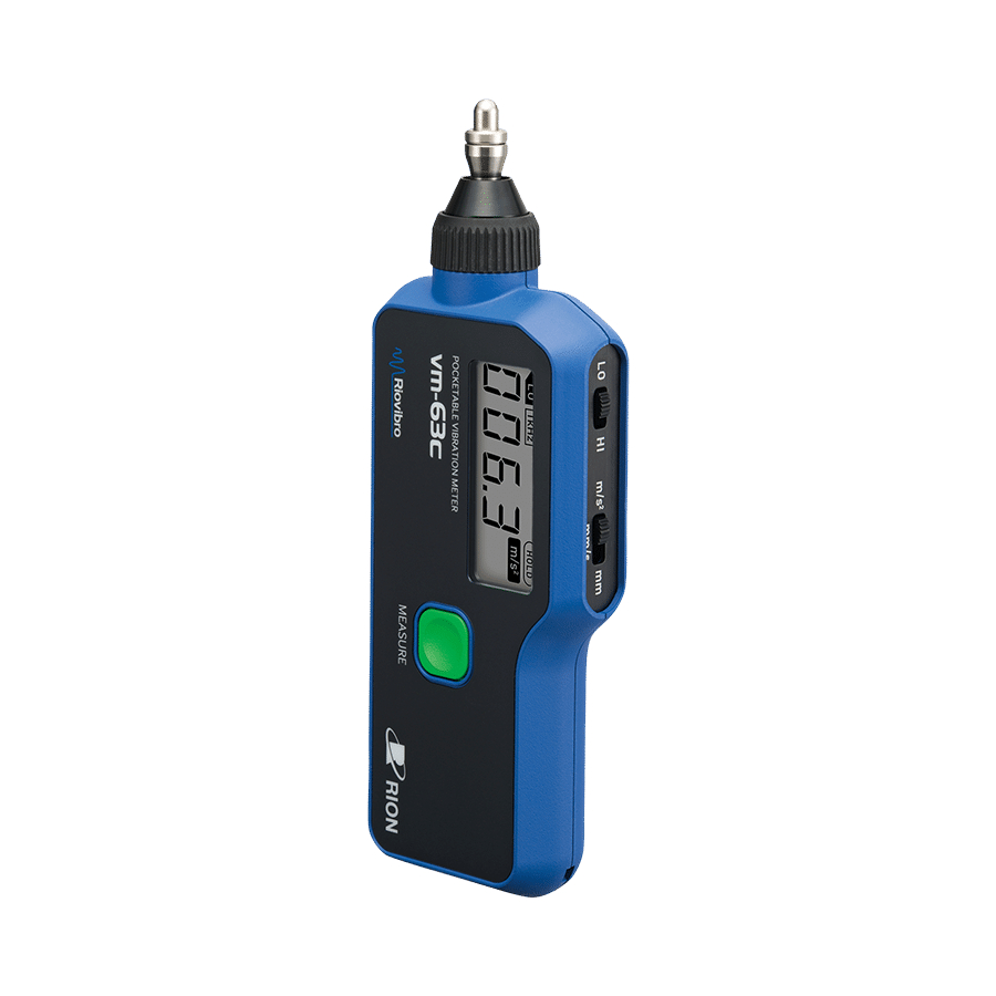
概 要 概 要 VM-63C は主に回転機械などの振動を簡便に測定する振 和 動計です。 文 本器先端部のピックアップを測定面に押し当て、ボタ ン 1 つの操作で測定が行えます。 振動測定は速度、変位でそれぞれ 10 Hz 〜 1 kHz の範 囲で測定が可能です。加速度は 10 Hz 〜 1 kHz、1 kHz 〜 15 kHz の 2 つの振動測定範囲が選択可能です。 本器は単 3 形アルカリ乾電池またはニッケル水素充電 池 2 本で動作します。 (マンガン乾電池も使用可能。 ) 本器は現場における日常点検や簡易診断向けの振動計... -
Page 12: 各部の名称と機能
各部の名称と機能 各部の名称と機能 正面 和 表示部 文 MEASUREボタン 振動検出部 表示部 測定値、測定モード、振動帯域、電池交換マークを 表示します。 振動検出部 測定対象物に押し当てます。 MEASURE ボタン 電源を入れるときに押します。また、測定するとき に押します(19 ページ参照) 。 上面 高域/低域選択スイッチ 加速度/速度/変位選択スイッチ 高域/低域選択スイッチ 加速度測定を選択した場合に、測定範囲を LO(Low レンジ:10 Hz 〜 1 kHz) 、HI(High レンジ:1 kHz 〜 15 kHz)から選択します。速度および変位測定選 択時はこのスイッチの選択の影響はなく、測定範囲 は常に 10 Hz 〜 1 kHz となります。... -
Page 13: 右側面
各部の名称と機能 加速度/速度/変位選択スイッチ 測定モードを選択します(16 ページ参照) 。 和 文 背面 電池室 電池室 単 3 型乾電池を 2 本入れます。 右側面 ストラップ 信号出力端子 取り付け部 ストラップ取り付け部 落下防止用のストラップ(別売)を取り付けできま す。 信号出力端子 交流信号の出力端子です。2 V Peak・FS が出力さ れます。イヤホン VP-37(別売)が接続できます。 注 意 過大振動入力の場合、イヤホンから 非常に大きな音が出て耳を傷める事 がありますのでご注意ください。... -
Page 14: 準 備
準 備 準 備 電池の入れ方 和 文 本器は単 3 形のアルカリ乾電池またはニッケル水素充 電池 2 本で動作します。 (マンガン乾電池も使用可能。 ) 上方向に持ち上げる 押しながら 単3形乾電池(2本) 1. 背面の電池室ふたのラッチ部分を押しながら、上方 向にふたを開けます。 2. 単 3 形乾電池 2 本を、+と−を間違えないように正 しく入れてください。 3. 電池室のふたを閉めます。 注 意 乾電池の極性「+」と「−」は間違えないよう正しく 入れてください。 極性を間違えると電池が破裂したり、 液もれを起こす場合があります。また、使用しないと きは、液もれなどの防止のため電池を取り出しておい てください。電池からもれた液が皮膚や衣服に付着し た場合は、すぐにきれいな水で洗い流してください。... -
Page 15: 乾電池の種類の切り替え
準 備 重 要 和 電池は 2 本とも同じ種類の新しいも 文 のを入れてください。異なる種類や新 旧混ぜての使用は故障の原因となりま す。 乾電池の種類の切り替え 電池ふたを開けると左上の部分に下図のような電池種 類設定スイッチがあります。 本器に使用する乾電池の種類に応じてスイッチを切り 替えます。設定した電池の種類に応じた電池残量が画 面に表示されます。ALKALI.(アルカリ乾電池または マンガン乾電池)または Ni-MH(ニッケル水素充電池) の 2 通りの設定ができます。 電池種類設定スイッチ... -
Page 16: A モード/ B モードの切り替え
準 備 A モード/ B モードの切り替え 和 電池ふたを開けると右上の部分に下図のような A/B 文 モード切替スイッチがあります。 A/Bモード切替スイッチ A モード選択時(VM-63A と同様の動作) 切替スイッチを「A」に設定した場合、本器は以下 のように動作します。 ・ MEASURE ボタンを押すと、電源が入ります。 ・ MEASURE ボタンを押し続けている間、表示部 に振動量を表示します。 ・ MEASURE ボタンを離すと、振動量がホールド され、表示部に「HOLD」が点灯します。 ・ 60 秒間なにも操作を行わないと、電源が自動で シャットダウンされます。... - Page 17 準 備 B モード選択時 切替スイッチを「B」に設定した場合、本器は以下 和 のように動作します。 文 ・ MEASURE ボタンを押すと、電源が入り、表示 部に振動量を表示します。 ・ 測定中に MEASURE ボタンを押すと、振動量 がホールドされ、表示部に「HOLD」が点灯し ます。 ・ 振動量のホールド中に、再度 MEASURE ボタ ンを押すと、ホールドが解除され、測定が再開 されます。 ・ MEASURE ボタンを約 3 秒間押し続けると、電 源がシャットダウンされます。...
-
Page 18: 測定の準備
準 備 測定の準備 和 1. 単 3 形乾電池 2 本を電池室に入れます。 文 2. MEASURE ボタンを押します。 表示部の電池残量が点滅している場合は、正しい測 定ができません。新しい電池と交換してください。 電池残量 3. 加速度/速度/変位選択スイッチで測定モードを選 択します。選択したモードが点灯します。 加速度 速度 変位 加速度測定(m/s )を選択した場合、振動数帯域 を高域/低域選択スイッチにより LO(Low レン ジ:10 Hz 〜 1 kHz) 、HI(High レンジ:1 kHz 〜 15 kHz)の 2 帯域から選択できます。選択した帯域 が点灯します。... - Page 19 準 備 シリコーンゴムカバー(付属品)の装着 和 本器を衝撃などから保護し、また手に持ったときに滑 文 りにくくします。 装着は下図のように行ってください。 ノート シリコーンゴムカバーを着ける際は以 下の点を気を付けてください。 ・側面部(スライドスイッチ部分)を しっかりはめてください。 ・本体のストラップホールとシリコー ンゴムカバーのニゲの位置を合わせ てください。 ・イヤホンジャックにキャップをはめ てください。...
-
Page 20: 画面の説明
画面の説明 画面の説明 和 電池残量 電池が消耗するに従い、表示が変化します。残量が 文 充分にある場合はなにも表示されません。 表示が点滅し始めたら正しい測定ができません。新 しい電池と交換してください。 電池残量 表示なし 残量大 点滅表示 電池交換... -
Page 21: 測 定
測 定 測 定 和 測定手順 文 1. MEASURE ボタンを押し電源を入れ、振動検出部を 測定対象物に押し当てます。押し当てる力は 500 g から 1 kg が適当です。 電源を入れてから、測定可能な状態になるまで、約 10 秒間ほどかかります。 設定したモードにより以降は手順が異なります (14 ペー ジ参照) 。 A モードに設定した場合(VM-63A と同様の操作が可能) 2. MEASURE ボタンを押し続けている間、表示部に 振動量が表示されます。 3. MEASURE ボタンをはなすと、振動量がホールド されるので、測定値を読みます。... - Page 22 測 定 4. 再度 MEASURE ボタンを押し続けることで、繰り 返し測定ができます。 和 5. 60 秒 間 な に も 操 作 を 行 わ な い と、 電 源 が 自 動 で 文 シャットダウンされます。 B モードに設定した場合 2. 表示部に振動量が表示されます。 3. 測定中に MEASURE ボタンを押すと、 振動量がホー ルドされるので、測定値を読みます。...
-
Page 23: 付 録
付 録 付 録 振動換算チャート検出部 和 文 主に正弦波振動に利用できます。 全ての振動が下図より振動数の換算ができるわけでは ありません。... -
Page 24: アタッチメントについて
付 録 アタッチメントについて 和 本器の振動検出部は、 測定用途によりアタッチメント S、 文 L(別売)およびアタッチメントを用いない場合の 3 種 を使い分けることができます。 アタッチメント S 出荷時の状態で、広い振動数範囲 にわたり振動数特性と再現性がす ぐれています。特に理由のない限 りこの状態で使用してください。 アタッチメント L 狭いところなど測定が難し い 場 合 に 用 い て く だ さ い。 加速度の HI レンジで使用す ることはできません。 アタッチメントなし (アタッチメントを用いない) 最も高域部特性がすぐれています (10 Hz 〜 15 kHz) 。 ノート... - Page 25 付 録 加速度測定での代表特性 和 文 Low レンジ...
- Page 26 付 録 和 文 アタッチメントなし アタッチメント S アタッチメント L High レンジ...
-
Page 27: 仕 様
仕 様 仕 様 適合規格 中国版 RoHS 和 CE マーキング 文 KC マーク 内蔵振動ピックアップ 圧電式加速度型(せん断構造) 測定範囲 加速度 0.1 〜 199.9 m/s PEAK(RMS× ) 速度 0.1 〜 199.9 mm/s RMS 変位 0.001 〜 1.999 mm P-P(RMS×2 ) 2 速度、変位の測定範囲は加速度 199.9 m/s PEAK を越えない範囲とする... - Page 28 仕 様 表示 モノクロセグメント液晶 和 指示特性 加速度 EQ PEAK 値(RMS 値 × ) 速度 RMS 値 文 変位 EQ P-P 値(RMS 値× 2 ) (P-P=PEAK × 2) 測定値 3 1/2 桁ディジタル(LCD) 表示周期 約 1sec ホールド機能 A モード: (VM-63A と同様) MEASURE ボタンを押している間は指示 値を更新し、離すと指示値をホールドす...
- Page 29 仕 様 操作部 MEASURE ボタン 和 電源の投入および遮断、振動量の表示お 文 よびホールド 高域/低域選択スイッチ 加速度測定時の振動数帯域を変更(HI / LO) 加速度/速度/変位選択スイッチ 測定モードを変更 変更可能な測定モード (加速度 ) mm/s(速度 ) mm(変位) 電池種類設定スイッチ 電池種類を変更(ALKALI.(アルカリ乾 電池 ) / Ni-MH(ニッケル水素充電池) ) A/B モード切替スイッチ 動作モードを変更(A / B) 電源 単 3 形電池 2 本(アルカリ乾電池/マン ガン乾電池/ニッケル水素充電池) オートシャットダウン(A モード)...
- Page 30 仕 様 消費電流 約 35 mA 電池寿命 約 50 時間(23℃ 50%RH、アルカリ乾電 和 池使用、イヤホン未使用) 文 使用温湿度範囲 ‑20℃〜 +60℃ 90%RH 以下(但し結露しないこと) 保存温湿度範囲 ‑20℃〜 +60℃ 90%RH 以下(但し結露しないこと) 寸法、質量 約 178 mm(H) 64 mm(W)×27 mm(D) 約 200 g(電池を含む) 付属品 単 3 形アルカリ乾電池 シリコーンゴムカバー アタッチメント S 取説シール ...
- Page 31 仕 様 φ10 φ25 和 文 単位 mm 外形寸法図...
- Page 32 和 文 http://www.rion.co.jp/ 本社/営業部 東京都国分寺市東元町 3 丁目 20 番 41 号 〒 185-8533 TEL ( 042) 359-7887 (代表) FAX (042) 359-7458 サービス窓口 リオンサービスセンター株式会社 東京都八王子市兵衛 2 丁目 22 番 2 号 〒 192-0918 TEL ( 042) 632-1122 FAX (042) 632-1140 西日本営業所 ...
- Page 33 VM-63C Vibration Meter (RIOVIBRO) Instruction Manual...
-
Page 34: Organization Of This Manual
Organaization of This Manual This manual describes the features and operation of the Vibra- tion Meter (RIOVIBRO) VM-63C. The manual contains the following sections. Outline Gives basic information on the unit. Controls and Features Briefl y identifi es and explains all parts of the unit. -
Page 35: For Safety
For Safety In this manual, important safety instructions are specially marked as shown below and next page. To prevent the risk of death or injury to persons and damage to the unit or peripheral equipment, make sure that all instructions are fully understood and observed. - Page 36 Important Disregarding inst ruct ions printed here incurs the risk of program dam- age or data loss. Note Denotes special information that is helpful in utilizing the capabilities of the unit but that is not directly related to safety.
- Page 37 WARNING When making measurements on exposed ro- tating parts or power train parts of machinery, proceed with utmost care to prevent accidents due to getting caught in the machinery. Important Remove the batteries when not using the unit. Otherwise there is a risk of malfunction and damage by battery fl uid leaks.
-
Page 38: Precautions
Precautions ● Operate the unit only as described in this manual. ● Do not drop the unit. Protect it from shocks and vibration. ● Do not store or use the unit in locations where the unit may be subject to splashes of water or high levels of dust, or air with high salt or sulphur content, or other gases or chemicals, or... - Page 39 This product can be used in any areas including residen- tial areas. The Product described in this manual is in conformity with the following European standards. Note: CE requirements are met provided that a core fi lter is fi tted to cable.
- Page 40 Contents Organization of This Manual ............. 32 For Safety ..................33 Precautions .................. 36 Outline ..................39 Controls and Features ..............40 Front View ................40 Top View ................41 Right Rear View ..............41 Bottom View ................. 42 Preparations ................43 Inserting the Battery .............
-
Page 41: Outline
概 要 Outline The VM-63C is a vibration meter designed for easy measure- ment of vibrations in rotational machinery or the like. Measurement is performed simply by holding the tip of the unit against the measurement object and operating one but- ton. -
Page 42: Controls And Features
Controls and Features Controls and Features Front View Display MEASURE Button Vibration detector attachment Display Shows the measurement value, measurement mode, vi- bration frequency range, and battery replacement indica- tion. Vibration detector attachment Press this section against the measurement object. MEASURE button Press this button to perform measurement (see page 51). -
Page 43: Top View
Controls and Features Top View High range / low range selector Acceleration / velocity / displacement selector High range / low range selector For acceleration measurement, this selector allows switching between LO (Low range: 10 Hz to 1 kHz) and HI (High range: 1 kHz to 15 kHz). -
Page 44: Bottom View
Controls and Features Right side View Signal output jack Strap attachment point Strap attachment point The optional hand strap for use when carrying the unit can be attached here. Signal output jack The AC output signal is supplied at this jack. The signal output is 2-volt peak at full-scale point. -
Page 45: Preparations
Preparations Preparations Inserting the Battery The unit is powered by two IEC R6 (size AA) batteries, either alkaline or nickel-hydride rechargeable types. (The use of manganese batteries is also possible.) Lift up Push Two IEC R6 (size AA) batteries 1. While pushing the latch of the battery compartment cov- er on the rear of the unit, lift the cover to remove it. - Page 46 Preparations CAUTION Take care not to mix up the battery “+” and “-” polarity. Otherwise the battery may explode, or battery fl uid leakage may occur. When not using the unit, the batteries should be removed to avoid the risk of battery fl uid leakage etc. If battery fl uid has come into contact with skin or clothes, imme- diately fl ush with plenty of clean water.
-
Page 47: Changing The Battery Type Setting
Preparations Changing the Battery Type Setting When the battery compartment cover is removed, the battery type selector switch on the top left becomes accessible, as shown below. Set the switch to the correct position, according to the battery type in use. This will ensure that the battery level indicator on the display of the unit operates correctly. -
Page 48: Mode A / Mode B Switching
Preparations Mode A / Mode B Switching When the battery compartment cover is removed, the A/B mode selector switch on the top right becomes accessible, as shown below. Mode A / B Switching switch Operation in Mode A: (same operation as VM-63A) When the mode selector is set to "A", the unit operates as follows. - Page 49 Preparations Operation in Mode B: When the mode selector is set to "B", the unit operates as follows. - Pressing the MEASURE button turns power on and causes the vibration amount to be shown on the display. - When the MEASURE button is pressed during a measurement, the vibration amount at that point is held on the display, and the "HOLD"...
-
Page 50: Measurement Preparations
Preparations Measurement Preparations 1. Insert two IEC R6 (size AA) batteries. 2. Press the MEASURE button. If the battery level indicator on the display is flashing, correct measurement is not possible. Replace the batteries with a fresh set. Battery status indication 3. -
Page 51: Mounting The Silicon Rubber Case (Supplied)
Preparations Mounting the Silicon Rubber Cover (Supplied) The case serves to protect the unit from shocks and provides a better grip to avoid dropping it. Insert the unit into the case as shown below. Note Observe the following precautions when mounting the silicon rubber cover. -
Page 52: Display Functions
画面の説明 Display Functions 和 Battery status indication This indicator changes according to the remaining 文 battery capacity. When the remaining capacity is high, nothing will be displayed. When the indicator starts to flash, correct measurement can no longer be performed. Replace the batteries with a fresh set. -
Page 53: Measurement
Measurement Measurement Measurement Procedure 1. While keeping the MEAS button depressed, hold the vibration detector against the measurement object. Use a pressure of about 500 g to 1 kg. If the MEAS button is pressed while power is off, the unit will require about 10 seconds until measurement is possible. - Page 54 Measurement 4. Holding down the MEASURE button again causes mea- surement to be resumed, allowing repeated measurement. 5. If no other operation is performed for 60 seconds, power will automatically be turned off. When Mode B is selected 2. The vibration amount is shown on the display. 3.
-
Page 55: Appendix
Appendix Appendix Vibration Conversion Chart T his cha r t is intended mainly for use with sine wave vibrations. It w i l l not b e p ossible to m a ke v ibr at ion f re quency conversions for all kinds of vibrations. -
Page 56: Vibration Detector Attachments
Appendix Vibration Detector Attachments The vibration detector of the VM-63C can be used without an attachment or with two kinds attachments, S (supplied) and L (option), to fi t the respective measurement requirements. With attachment S The unit is delivered in this con- dition. - Page 57 Appendix Note O n ly for ca ses where t he t ip ca n b e brought into full surface contact with the measuring object. If necessary, use grease or similar to achieve a flat surface. Otherwise correct measurement may not be possible. Do not use excessive force when fastening the attachment.
- Page 58 Appendix Without attachment Attachment S Attachment L Frequency(Hz) High range...
-
Page 59: Specifications
Specifi cations Specifi cations Applicable standards China RoHS CE marking KC marking Built-in accelerometer Piezoelectric accelerometer (shear-type) Measurement range Acceleration: 0.1 to 199.9 m/s PEAK ( RMS× ) Velocity: 0.1 to 199.9 mm/s RMS Displacement: 0.001 to 1.999 mm P-P ( RMS×2 )... - Page 60 Specifi cations Display Monochrome segmented LCD Indication characteristic Acceleration: EQ PEAK ( RMS× ) Velocity: Displacement: EQ P-P ( RMS×2 ) ( P-P=PEAK×2 ) Measurement value 3-1/2 digit digital display ( LCD ) Display update cycle 1 sec Hold function Mode A (same as VM-63A) Display value is updated while MEASURE button is kept depressed and is held when...
- Page 61 Specifi cations Operation part MEASURE button Serves for turning power on and off, and for displaying and holding the vibration amount. High range/low range selector switch Changes the vibration frequency range for acceleration measurement (HI /LO). Acceleration/velocity/displacement selector switch Changes the measurement mode. Available measurement modes (Acceleration) mm/s (Velocity)
- Page 62 Specifi cations Keeping the MEASURE button depressed for about 3 seconds turns power off. Current consumption Approx. 35 mA Battery life About 50 h (23 ℃ 50%RH, Use of ALKALI.: alkaline batteries, unused earphone) Environmental conditions for operation -20 ℃ to +60 ℃ , to 90%RH (no condensa- tion )...
- Page 63 Specifi cations φ10 φ25 Unit : mm Dimensional Drawings...
- Page 64 3-20-41 Higashimotomachi, Kokubunji, Tokyo 185-8533, Japan http://www.rion.co.jp/english/...
- Page 65 VM-63C VM-63C 振动计(RIOVIBRO) 振动计(RIOVIBRO) 使用说明书 使用说明书...
- Page 67 中文说明书的构成 中 本使用说明书对振动计(RIOVIBRO)VM-63C 的功能和使 文 用方法等进行说明。 本使用说明书由以下各章构成。 概要 对基本项目进行说明。 各部位的名称及功能 简单说明主体各部位的按钮,开关,端子等的名称与功能。 准备 记载了电池的安装方法以及测量的准备工作。 画面说明 对数字显示屏中显示的项目进行说明。 测量 对测量相关的基础知识进行说明。 附件说明 对使用说明贴纸进行说明。 附录 记载了振动换算表,检测部位的配件。 规格 记载了本仪器的规格。...
- Page 68 安全使用注意事项 中 本说明书中,会标注如下标识提醒用户注意。所记载的内容 是为确保生命和人身安全,防止本仪器及周边设备等受到损 文 坏的必须注意事项。 警 告 若无视此处所记载的注意事项,将 可能无法确保生命和人身安全。 注 意 若无视此处所记载的注意事项,将 可能会对人身或周边设备造成伤害 或损坏。...
- Page 69 中 文 重 要 若无视此处所记载的注意事项,将 可能导致本仪器出现故障。 备 注 不会对安全造成直接的影响,但是 为了能够正确使用本仪器的功能而 记载的注意事项。...
- Page 70 中 警 告 文 在测量暴露在外的旋转部位,动力传递部位等时, 请多加注意不要被机器卷入其中。 重 要 不使用时,请将干电池取出。干电池漏液可能会导致仪器 故障。 电池请放入 2 节相同种类的新电池。种类不同或新旧电池 混用可能导致仪器故障。 本产品符合 CE 标准。 上述规格为有芯电缆适用的规格。...
- Page 71 使用注意事项 中 ● 使用仪器时请务必遵照使用说明书进行操作。 文 ● 请注意不要将本仪器掉落,或施加外力对其振动或撞 击。 ● 请勿在下述场所中使用或存放本仪器。 多灰尘的场所,可以溅到水或油等液体的场所 可能会受到盐分,硫磺成分,化学药品或煤气等 负面影响的场所 高温(60℃以上) 、高湿(90%RH 以上) 、阳光直 射的场所 ● 不使用时,请将干电池取出。干电池漏液可能会导致 仪器故障。 ● 请勿拆卸,改造本仪器。 ● 本仪器以及传感器,请每 1 年接受一次定期检查。 (灵 敏度再校正、在工厂进行检查、收费) ● 请勿用手指或笔等按压液晶显示屏。这可能会导致显 示不良或运行不良。 ● 万一发生故障时,切勿擅自处理,请联系销售店或本 公司维修窗口(参照 29 页) 。 ● 电池废弃时,请按照国家或地方自治体的条例进行废 弃。...
- Page 72 中 文 环保使用期限标识 该标记用于表示在中国销售的电子信息产品的环保使用期限。 只要您遵守该产品在安全和使用等方面的规定,则从制造之 日开始算起的使用年限内,它不会对环境、人体及财产带来 严重影响。 有毒有害物质或元素的名称及含量 有毒有害物质或元素 部件名称 铅 汞 镉 六价铬 多溴联苯 多溴二苯醚 (Pb) (Hg) (Cd) (Cr(VI)) (PBB) (PBDE) VM-63C × × × × × × ○ : 表示该有毒有害物质在该部件所有均质材料中的含量均在 GB/T 26572 标准规定的限 量要求以下。 × : 表示该有毒有害物质至少在该部件的某一均质材料中的含量超出 GB/T 26572 标准规 定的限量要求。...
- Page 73 目 次 中 中文说明书的构成 ................1 文 安全使用注意事项 ................2 使用注意事项 ...................5 概 要 ....................8 各部位的名称及功能 ...............9 正面....................9 上面....................9 背面....................10 右侧面 ..................10 准 备 ....................11 电池的安装方法...............11 切换干电池的种类 ..............12 切换 A 模式/ B 模式 .............13 测量准备工作 ................15 安装硅胶壳(附件) ..............16 画面说明 ..................17 测 量 ....................18 测量步骤...
-
Page 74: 概 要
概 要 概 要 VM-63C 是主要用来对旋转机械等的振动进行简易测量的 中 振动计。 文 将本仪器前端部位的传感器抵住测量面,通过按下按钮 的一键操作便可完成测量。 振动测量可分别在 10 Hz ~ 1 kHz 的范围内对速度,位 移进行测量。加速度可选择 10 Hz ~ 1 kHz,1 kHz ~ 15 kHz 的 2 个振动测量范围。 本仪器使用 2 节 5 号碱性干电池或镍氢充电电池即可运 行。 (也可以使用碳性干电池。 ) 本仪器是适合现场日常检查及简单诊断的振动计。精密 诊断及分析建议使用通用振动计或振动分析器。... -
Page 75: 各部位的名称及功能
各部位的名称及功能 各部位的名称及功能 正面 中 显示屏 文 MEASURE 按钮 振动检测部位 显示屏 显示测量值,测量模式,振动范围,更换电池标志。 振动检测部位 抵住测量对象物。 MEASURE 按钮 开启电源时按下此按钮。此外,测量时也需按下此按 钮(参照 18 页) 。 上面 高频范围/低频范围选择开关 加速度/速度/位移选择开关 高频范围/低频范围选择开关 选 择 加 速 度 测 量 时, 从 LO( 低 频 范 围 : 10 Hz ~ 1 kHz)... -
Page 76: 右侧面
各部位的名称及功能 加速度/速度/位移选择开关 选择测量模式(参照 15 页) 。 中 文 背面 电池盒 电池盒 装入 2 节 5 号干电池。 右侧面 安装挂绳的位置 信号输出端子 安装挂绳的位置 可以安装防掉落用的挂绳(另售) (参照 16 页) 。 信号输出端子 交流信号的输出端子。输出 2 V Peak・FS。可以连接 耳机 VP-37(另售) 。 注 意 输入过大振动时,会从耳机中听到非 常大的声音,可能会损伤耳朵,敬请 注意。... -
Page 77: 准 备
准 备 准 备 电池的安装方法 中 文 本仪器使用 2 节 5 号碱性干电池或镍氢充电电池即可运 行。 (也可以使用碳性干电池。 ) 向上方抬起 按住 5号干电池(2节) 1. 按住背面的电池盒盖卡扣的同时,向上打开电池盖。 2. 将 2 节 5 号干电池按照正确的正负极方向安装。 3. 盖上电池盒盖。 注 意 请正确安装干电池的正负极。如正负极装反,可能会导 致电池破裂或漏液。此外,在不使用时,为防止发生漏 液等情况,请取出电池。电池的漏液如粘附到皮肤或衣 服上时,请立即用清水冲洗干净。... -
Page 78: 切换干电池的种类
准 备 重 要 中 关于电池,请放入 2 节相同种类的新电 文 池。种类不同或新旧电池混用可能导致 仪器故障。 切换干电池的种类 打开电池盒盖后,左上部位如下图所示,设有可以设置 电池种类的开关。 根据本仪器所使用的干电池种类切换开关。根据设置的 电池种类在显示屏中显示电池余量。可以从2种选择方 式中选择设置为 ALKALI.(碱性干电池或碳性干电池)或 Ni-MH(镍氢充电电池) 。 电池种类设置开关... -
Page 79: 切换 A 模式/ B 模式
准 备 切换 A 模式/ B 模式 中 打开电池盒盖后,右上部位如下图所示,设有可切换 A 文 / B 模式的开关。 切换 A 模式/B 模式 选择 A 模式时(可与 VM-63A 同样运行) 将切换开关设为“A”时,本仪器将运行如下。 ・ 按下 MEASURE 按钮,开启电源。 ・ 持续按住 MEASURE 按钮期间,显示屏中将显示 振动量。 ・ 松开 MEASURE 按钮后,则捕捉振动量,显示屏 中“HOLD”将亮灯。 ・ 若 60 秒时间内不进行任何操作, 电源将自动关闭。... - Page 80 准 备 选择 B 模式时 将切换开关设为“B”时,本仪器将运行如下。 中 ・ 按下 MEASURE 按钮,开启电源,显示屏中将显 文 示振动量。 ・ 测量过程中按下 MEASURE 按钮,则捕捉振动量, 显示屏中“HOLD”将亮灯。 ・ 捕捉振动量的过程中,再次按下 MEASURE 按钮, 将废除捕捉到的数据,再次开始测量。 ・ 持续按住 MEASURE 按钮约 3 秒钟,电源将关闭。...
-
Page 81: 测量准备工作
准 备 测量准备工作 中 1. 将 2 节 5 号干电池安装到电池盒内。 文 2. 按下 MEASURE 按钮。 显示屏中的电池余量闪烁时,将无法正确测量。请更 换新电池。 电池余量 3. 通过加速度/速度/位移选择开关来选择测量模式。 所选的模式将亮灯。 加速度 速度 位移 选择加速度测量(m/s )时,通过高频范围/低频范 围选择开关, 从 LO (低频范围: 10 Hz ~ 1 kHz) , HI ( 高 频范围 : 1 kHz ~ 15 kHz)这 2 个范围中选择振动频 率范围。所选的频率范围将亮灯。... -
Page 82: 安装硅胶壳(附件
准 备 安装硅胶壳(附件) 中 为了保护本仪器不受外力撞击等,以及手持时不易滑落。 文 请按照下图进行安装。 备注 安装硅胶壳时,请注意以下几点。 ・请将侧面部位(滑动开关部位)完全 嵌入。 ・请将主体的挂绳孔与硅胶壳的相应位 置对准。 ・请将防尘塞插入耳机插孔。... -
Page 83: 画面说明
画面说明 画面说明 中 电池余量 随着电池的消耗,显示内容也随之变化。电量充足时, 文 无任何显示。如果开始闪烁显示,则无法进行正确的 测量。请更换新电池。 电池余量 无显示 电量充足 闪烁显示 更换电池... -
Page 84: 测 量
测 量 测 量 中 测量步骤 文 1. 按下 MEASURE 按钮开启电源,将振动检测部位抵住 测量对象物。适合的对准力度为 500 g 到 1 kg。 从开启电源到可测量的状态大约需 10 秒时间。 设置的模式不同,以下的步骤也有所不同(参照 13 页) 。 设置为 A 模式时(可与 VM-63A 同样操作) 2. 持续按住 MEASURE 按钮期间,显示屏中将显示振动 量。 3. 松开 MEASURE 按钮后,将捕捉振动量,读取测量值。... - Page 85 测 量 4. 再次持续按住 MEASURE 按钮后,则可以反复测量。 中 5. 若 60 秒时间内不进行任何操作,电源将自动关闭。 文 设置为 B 模式时 2. 显示屏中显示振动量。 3. 测量过程中按下 MEASURE 按钮后,将捕捉振动量, 读取测量值。 4. 再次按下 MEASURE 按钮后,则废除捕捉到的数据, 可以反复测量。 5. 持续按住 MEASURE 按钮约 3 秒钟, 电源将关闭。 此外, 不会自动关闭电源。 备注 振动频率范围在 10 Hz ~ 1 kHz 的振动 测量,...
-
Page 86: 附 录
附 录 附 录 振动换算图表检测部位 中 文 主要可以用于正弦波振动。 所有的振动并非都可以通过下图换算出振动频率。... -
Page 87: 关于配件
附 录 关于配件 中 本仪器的振动检测部位,根据测量用途可以分为配件 S, 文 L(另售)及不使用配件的 3 种形式。 配件 S 出厂时的标配状态,适用于广泛 配件S 的振动频率范围,拥有卓越的振 动频率特性与再现性。如没有特 殊的理由,请在使用时保持此状 态。 配件 L 配件L 请用于狭窄场所等测量困难 的情况。无法用于加速度的 HI 范围。 无配件 (不使用配件) 无配件 在高频率范围部特性最好 (10 Hz ~ 15 kHz) 。 备注 仅限在前端部可以与测量对象物的表面 接触的情况下能不使用配件。 请在表面涂抹润滑脂等,让表面变得平 坦。否则有时会无法正确测量。 安装配件时,请勿过于用力扭紧。... - Page 88 附 录 加速度测量的代表特性 中 文 无配件 配件S 配件L 频率(Hz) 低范围...
- Page 89 附 录 中 文 无配件 配件S 配件L 频率(Hz) 高范围...
-
Page 90: 规 格
规 格 规 格 适用规格 中国版 RoHS 中 CE 认证 文 KC 认证 内置振动传感器 压电式加速度型(剪切结构) 测量范围 加速度 0.1 ~ 199.9 m/s PEAK(RMS× ) 速度 0.1 ~ 199.9 mm/s RMS 位移 0.001 ~ 1.999 mm P-P(RMS×2 ) 将速度,位移的测量范围设为不超过加速 度 199.9 m/s PEAK 的范围... - Page 91 规 格 显示 黑白段码液晶屏 指示特性 加速度 EQ PEAK 值(RMS 值 × ) 中 速度 RMS 值 文 位移 EQ P-P 值(RMS 值 ×2 ) (P-P=PEAK×2) 测量值 3 1/2 位数字(LCD) 显示周期 约 1 sec 捕捉功能 A 模式 : (与 VM-63A 相同) 在按下...
- Page 92 规 格 操作部分 MEASURE 按钮 中 开启及关闭电源,显示及捕捉振动量 文 高频范围/低频范围选择开关 更改加速度测量时的振动频率范围(HI / LO) 加速度/速度/位移选择开关 更改测量模式 可更改的测量模式 (加速度 ) mm/s(速度 ) mm(位移) 电池种类设置开关 更改电池种类(ALKALI.(碱性干电池 ) / Ni-MH(镍氢充电电池) ) A / B 模式切换开关 更改运行模式(A / B) 电源 2 节 5 号电池(碱性干电池/碳性干电池 /镍氢充电电池) 自动关闭(A 模式) 按下...
- Page 93 规 格 使用温湿度范围 -20℃~ +60℃ 90%RH 以下(但未冷凝) 中 文 保存温湿度范围 -20℃~ +60℃ 90%RH 以下(但未冷凝) 尺寸,重量 约 178 mm(H)×64 mm(W)×27 mm(D) 约 200 g(包括电池) 附件 5 号碱性干电池 硅胶壳 配件 S 使用说明书标签 专用识别器 通过 VM-63C 辨别标签确认产品 的方法 使用说明书 内容物明细表兼理音产品保修单 另售品 配件 L VP-53Y 耳机...
- Page 94 规 格 φ10 φ25 中 文 单位 mm 外形尺寸图...
- Page 95 规 格 中 文 http://www.rion.co.jp/ 总部/营业部 东京都国分寺市东元町 3-20-41 邮编 185-8533 TEL (042) 359-7887 (总机) FAX (042) 359-7458 上海理音科技有限公司 上海市徐汇区宜山路 900 号科技产业化大楼 C 区 501 室 TEL (021) 54235082 FAX (021) 54235266 广州办事处 广东省广州市天河区体育东路 122 号羊城国际商贸中心西栋 25 楼 C10 室...
Need help?
Do you have a question about the RIOVIBRO and is the answer not in the manual?
Questions and answers