
Related Manuals for Rion VM-55


Summary of Contents for Rion VM-55
- Page 1 INSTRUCTION MANUAL Vibration Level Meter VM-55 3-20-41 Higashimotomachi, Kokubunji, Tokyo 185-8533, Japan https://www.rion.co.jp/english/...
- Page 3 Organization of this manual This manual describes the features, operation and other aspects of the vibration level meter VM-55. If the unit is used together with other equipment to confi gure a measurement system, consult the documentation of all other components as well.
- Page 4 Store Operations Explains how to store measurement data. Card capacity and store time Lists the data store time corresponding to the SD memory card capacity, etc. Input/output connectors Explains the input and output connectors of the unit. Default Settings Lists the factory default settings of the unit. Setup Files Explains how to start up the unit using settings saved in a setup fi le.
-
Page 5: For Safety
FOR SAFETY In this manual, important safety instructions are specially marked as shown below. To prevent the risk of death or injury to persons and severe damage to the unit or peripheral equipment, make sure that all instructions are fully understood and observed. - Page 6 Precautions Operate the unit only as described in this manual. Take care not to drop the unit, and protect it from shocks and vibrations. Take care not to drop the accelerometer, and protect it from shocks. Ambient conditions for operation of the unit are as follows: temperature range −10°C to +50°C, relative humidity up to 90%RH.
- Page 7 In order to maintain the “water and dust resistant performance” of the unit, observe the following precautions. Make sure that the battery compartment lid, the side cover and the top cover of the unit are fi rmly closed. Do not open the battery compartment lid while the unit is wet. Do not leave the unit in a wet state.
- Page 8 Precautions for opening the case Before opening the case and removing any equipment, place the case on sturdy, fl at table or on the fl oor. Then open the case fully as shown below. Never open the case while it is standing upright.
- Page 9 This product can be used in any areas including residential areas. To conform to the EU requirement of the Directive on Waste Electrical and Electronic Equipment, the symbol mark on the right is shown on the instrument.
-
Page 10: Table Of Contents
Contents FOR SAFETY ................iii Outline ....................1 Controls and features ..............3 Front view ..................3 Right side view ................7 Top view ..................9 Bottom view ................10 Accelerometer and extension cord ........... 11 Preparations ..................12 Removing the equipment from the case ........12 Power ..................13 Power on/off ................ - Page 11 Time-level display screen ............52 Indicator messages ..............53 Menu list screen ...............54 Measurement .................72 Vibration level (L ) and vibration acceleration level (L measurement ................72 Equivalent continuous level (L ) measurement .... 74 vaeq Other processed value measurement ........77 Store Operation ................78 Manual mode operation ............
- Page 12 Optional Accessories ..............117 Extension cord ............... 117 EC-02S – EC-54S conversion cord EC-54ST ......119 Printer DPU-414 / BL2-58 ............119 Level recorder LR-07 ............. 122 Program options ..............123 Serial Interface ................124 RS-232C ................124 USB ..................127 Connection to a computer ............. 135 Disconnection from the computer ..........
-
Page 13: Outline
Outline The VM-55 is a vibration level meter compliant with the requirements of the Measurement Act and of the Japanese Industrial Standards for Vibration Level Meters (JIS C 1510:1995, JIS C 1517:2014). The unit is designed mainly for measuring ground vibrations in order to evaluate vibration pollution. - Page 14 Outline Block diagram...
-
Page 15: Controls And Features
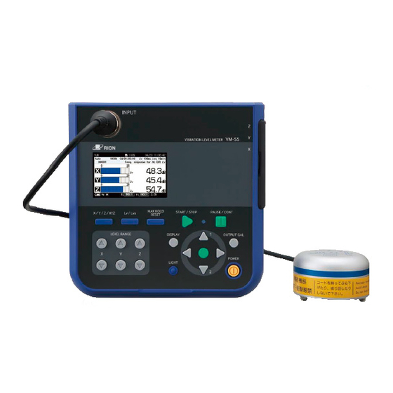
Controls and features Front view INPUT connector Display Control section INPUT connector The 3-axis accelerometer PV-83C is to be connected here, using the supplied EC-54S cord. If the accelerometer is to be installed at a greater distance, optional extension cord can also be used. Display The display of the unit is a backlit LCD panel. - Page 16 Controls and features Control section MAX HOLD RESET key START/STOP key Lv/Lva key Indicator LED X/Y/Z/XYZ key PAUSE/CONT key OUTPUT CAL key LEVEL RANGE key POWER key MENU/ENTER key DISPLAY key LIGHT key LEVEL RANGE keys These keys control the level range for the X, Y, Z axis. key switches the level range up, and the key switches the level range down.
- Page 17 Controls and features Indicator LED Lights/fl ashes in red or blue to indicate the operation or status of the unit. PAUSE/CONT key Press the key to pause measurement (processing), and press the key again to resume measurement (processing). During pause in manual processing, the indicator LED fl ashes in blue. Note The PAUSE key does not function while the store mode is Auto or Timer Auto (when the optional VX-55EX...
- Page 18 Controls and features DISPLAY key This key switches measurement screen display. Each push of the key cycles through the settings in the following order: Measurement screen Max Hold screen Processed data screen Time-level screen Measurement screen In addition, this key is used to bring up an explanation of the item on the screen by the help system.
-
Page 19: Right Side View
Controls and features Right side view OUTPUT connectors I/O connector Side cover USB connector DC IN connector Side cover This cover protects the connectors on the right side during transport or storage. Removing the cover gives access to the connectors shown above. Important To keep the water and dust resistant performance, close tightly the side cover of the unit. - Page 20 Controls and features USB connector (mini B) Serves for connection to a computer. DC IN connector The optional AC adapter NC-98 series can be connected here for powering the unit from an AC outlet (100 V to 240 V AC ). The optional battery pack BP-21A can also be connected here.
-
Page 21: Top View
Controls and features Top view Top cover SD card slot Top cover This cover protects the connectors on the top during transport or storage. Removing the cover gives access to the connectors shown above. Important To keep the water and dust resistant performance, close tightly the top cover of the unit. -
Page 22: Bottom View
Controls and features Bottom view Model plate Battery compartment Name plate Shows the serial number of the unit and the accelerometer as well as the manufacturing date of the unit and other information. Battery compartment Eight batteries (IEC R6, size AA) are inserted here. The [power-on mode] switch is in the battery compartment (see page 18). -
Page 23: Accelerometer And Extension Cord
Controls and features Accelerometer and extension cord For measurement, the 3-axis accelerometer PV-83C is required. Plug one end of the supplied EC-54S cord into the accelerometer and plug the other end into the INPUT connector on the unit. For more information, see the section on accelerometer placement and connection in “Preparations”... -
Page 24: Preparations
Preparations Removing the equipment from the case Before opening the case and removing any equipment, place the case on sturdy, fl at table or on the fl oor. Then open the case fully as shown below. Caution Never open the case while it is standing upright. -
Page 25: Power
Preparations Power The unit can be powered by eight IEC R6, size AA batteries (alkaline, rechargeable nickel metal-hydride), the optional AC adapter NC-98 series, and the optional battery pack BP-21A. Rechargeable nickel metal-hydride batteries can be used, but the unit does not have a facility for charging the batteries. - Page 26 Preparations Inserting the batteries 1. Remove the battery compartment lid as shown below. 2. Insert eight IEC LR6, size AA batteries, paying attention to the polarity as indicated in the compartment. 3. Replace the cover. IEC LR6 (sizeAA) battery × 8 Caution Take care not to reverse the (+) and (−) polarity when inserting the batteries.
- Page 27 Battery life may also be shorter when the program option is operating. Important The rechargeable nickel metal-hydride battery is not charged by the VM-55. Select the used battery type by the [System (Language)] on the menu list screen (see page 56).
- Page 28 Preparations AC adapter To operate the unit with the AC adapter, connect it as shown below. Important To prevent the risk of damage, do not use any AC adapter other than the NC-98 series. The AC adapter NC-34 series used for the con- ventional vibration level meter cannot be used.
-
Page 29: Power On/Off
Preparations Power on/off To turn the unit on Hold down the POWER key until the power-on screen appears (at least 2 seconds). When the screen is shown, release the POWER key. After the unit has been started, the measurement screen appears. During start up, the indicator LED fl ashes red blue Indicator LED... - Page 30 Preparations Power-on mode switch Opening the battery compartment as shown below gives access to a switch labeled “A-B”. Normally the “A” position is used. Setting this switch to the ‘’B’’ position allows the unit to be turned on simply by supplying power to the DC IN connector.
-
Page 31: Accelerometer Placement And Connection
Preparations Accelerometer placement and connection Vibration axis Environmental vibrations are normally measured in two horizontal planes (front/back and left/right) and one vertical plane. This means that complex vibration phenomena are reduced to three axes (X, Y, Z), for easier observation. The axes are defi ned as follows (facing the vibration source). - Page 32 Turn the locking ring clockwise to fasten the plug. 2. Insert the plug at the other end of the cord into the Input connector on the VM-55, aligning the guide on the plug with the connector. Turn the locking ring clockwise to fasten the plug. Important The accelerometer is a precision device.
- Page 33 Preparations Important Never suspend the accelerometer by its cord or pull at the cord. Otherwise cord breaks may occur.
- Page 34 Otherwise cord breaks due to twisting may occur. Do not connect to reel EC-54S (supplied) Do not connect to Input Do not connect to accelerometer cord connector on VM-55...
- Page 35 Preparations 3-axis accelerometer PV-83C Connector Optional extension cord can be connected here. EC-54SB (10 m) EC-02SD (50 m; with reel) EC-02SE (100 m; with reel) Ring When a cord reel is used, Plug the EC-54S (3 m) must also be connected. Supplied cord EC-54S (3 m) Input connector...
-
Page 36: Sd Memory Card And Program Cards
If the SD memory card is removed while data is being read or written to the card, the data may be destroyed. Use SD memory cards provided by Rion. The performance of other cards is not guaranteed. Note that we assume no responsibility for any damage or loss of stored measurement data. -
Page 37: Connection To Printer (Dpu-414, Bl2-58)
Refer to the illustration below and connect the I/O connector on the right side of the VM-55 to the input of the printer, using the separately available printer cable. The correct combination of printer model and cable is as follows. - Page 38 Preparations Vibration level meter settings when using a printer When using a printer, perform the following steps to set the baud rate for the vibration level meter. 1. Press the MENU/ENTER key to bring up the menu list screen. 2. Use the keys to select [Display / I/O] and press the MENU/ENTER key.
- Page 39 A printout showing the current status of the printer is produced. An example showing suitable software DIP switch settings for use of the printer with the VM-55 is shown below. (The actual printout will be in a different font.) [DIP SW setting mode]...
- Page 40 - BAUD RATE: Select one of the available settings: 9600, 19200, 38400, 57600, 115200 (bps) * Match the setting to the setting of the VM-55. Leave all other printer settings in the default condition. 4. When the setting is complete, the indication [SETTING MODE END] is printed.
-
Page 41: Connection To A Level Recorder (Lr-07) And Data Recorder (Da-21, Da-40)
Connection to a level recorder (LR-07) and data recorder (DA-21, DA-40) Connect the OUTPUT connector on the right side of the VM-55 with an input connector of level recorder (LR-07) and data recorder (DA-21, DA-40), using the optional BNC - Pin output cord CC-24 as shown below. The performance of other cables is not guaranteed. -
Page 42: Connection To A Frequency Analyzer
Preparations Connection to a frequency analyzer Connect the OUTPUT connector on the right side of the VM-55 with an input connector of frequency analyzer, using the optional BNC - Pin output cord CC-24 as shown below. The performance of other cables is not guaranteed. -
Page 43: Connection To A Computer
Preparations Connection to a computer Connect the USB connector on the right side of the VM-55 with a USB connector of a computer, using the optional (generic) A - mini B USB cable as shown below. An SD memory card inserted in the unit will be recognized as a removable disk by the computer when connected via USB, without having to install a USB driver. -
Page 44: Setting The Date And Time
Preparations Setting the date and time The unit incorporates a clock which allows recording the date and time along with measurement data. Set the date and time as described below. 1. Press the MENU/ENTER key to bring up the menu list screen. 2. - Page 45 Preparations System screen Clock settings screen...
-
Page 46: Measurement In A Dark Location
Preparations Measurement in a dark location Pressing the LIGHT key will turn on the display backlight, for easier reading in a dark location. The backlight operation pattern can be controlled via a menu, as follows. 1. Press the MENU/ENTER key to bring up the menu list screen. 2. - Page 47 Preparations System screen Backlight/LCD settings screen...
-
Page 48: Eco Setting (Power-Saving Mode)
Preparations Eco setting (Power-saving mode) The Eco setting enables the power saving feature. A long-time measurement can be performed using batteries only. 1. Press the MENU/ENTER key to bring up the menu list screen. 2. Use the keys to select [System (Language)] and press the MENU/ENTER key. - Page 49 Preparations System screen Execution confi rmation screen...
-
Page 50: Comparator Output
Preparations Comparator output This is an open collector output that can be used to control external equipment such as alarm device. When the optional Extended Function Program VX-55EX is not installed, the comparator output cannot be set. 1. Press the MENU/ENTER key to bring up the menu list screen. 2. - Page 51 Preparations Display / I/O screen Comparator screen...
- Page 52 Preparations Connecting external equipment Connect the I/O connector on the right side of the VM-55 with an input connector of external equipment, using the optional comparator output cable CC-42C as shown below. The performance of other cables is not guaranteed.
-
Page 53: Language Selection
Preparations Language selection The language used for displaying messages and menus can be selected as follows. 1. Press the MENU/ENTER key to bring up the menu list screen. 2. Use the keys to select [System (Language)] and press the MENU/ENTER key. The system screen appears. 3. -
Page 54: Calibration
Preparations Calibration When using external equipment to record measurement data, level calibration should be performed as follows. 1. Press the MENU/ENTER key to bring up the menu list screen. 2. Use the keys to select [Display / I/O] and press the MENU/ENTER key. - Page 55 Preparations 6. Use the keys to select [Type] and press the MENU/ENTER key. The type screen appears. 7. Use the keys to select the type (AC OUT, DC OUT) and press the MENU/ENTER key. AC OUT: The OUTPUT connectors provide AC signal. DC OUT: The OUTPUT connectors provide DC signal.
-
Page 56: Reading The Display
Reading the Display Measurement screen display The illustration below shows all elements of the display for explanation purposes. In actual operation, such a screen will not be shown. (In case of 1 channel screen indication,) Operation/measurement elapsed time Comparator indication SD memory card insertion indicator Measurement time/ SD memory card remaining capacity... - Page 57 Reading the Display Mode of analysis Indicates the condition of the display screen. Measurement time/Total measurement time When the store mode is Manual, the measurement time is displayed. When the store mode is Auto, the total measurement time is displayed (see page 82, 88).
- Page 58 Reading the Display Bar graph level range Shows the upper and lower limit of the bar graph. The range can be changed using the LEVEL RANGE key on the control section. Overload indication When a signal overload condition of the vibration level or the vibration acceleration level is detected, the indication (white on black) is shown for at least 1 second.
- Page 59 Reading the Display Marker 1 / marker 2 display During measurement, pressing the key will bring up the indication “MARKER-1” and pressing the key will bring up the indication “MARKER-2” on the display, and the respective marker will be recorded along with the measurement data (see page 92).
- Page 60 Reading the Display Measurement in progress symbol When a measurement is in progress, the symbol fl ashes. The indicator LED also fl ashes in red. During auto store, the symbol also fl ashes. The indicator LED fl ashes in red. During measurement standby, the symbol is shown.
-
Page 61: Measurement Screen
Reading the Display Measurement screen When the measurement screen is displayed, pressing the Lv/Lva key changes the L value display as shown below. Measurement screen (3 channels display) When the measurement screen is displayed, pressing the X/Y/Z/XYZ key changes the channel display as shown below. Pressing the Lv/Lva key changes the L value display. -
Page 62: Max Hold Display Screen
Reading the Display Max Hold display screen When the measurement screen is displayed, pressing the DISPLAY key brings up the Max Hold display screen as shown below. Pressing the X/Y/Z/XYZ key switches the vibration axis (channel) to be shown on the display. Pressing the MAX HOLD RESET key resets the value of the max hold function. -
Page 63: Processed Data Display Screen
Reading the Display Processed data display screen When the Max Hold display screen is displayed, pressing the DISPLAY key brings up the processed data display screen as shown below. Pressing the X/Y/Z/XYZ key switches the vibration axis (channel) to be shown on the display. -
Page 64: Time-Level Display Screen
Reading the Display Time-level display screen When the processed data display screen is displayed, pressing the DISPLAY key brings up the time-level display screen as shown below. Pressing the X/Y/Z/XYZ key switches the vibration axis (channel) to be shown on the display. Pressing the MAX HOLD RESET key resets the value of the max hold function. -
Page 65: Indicator Messages
Reading the Display Indicator messages When keys such as START/STOP or PAUSE/CONT are pressed, indicator messages such as shown below will appear on the display for about 1 second. When START/STOP key was pressed and processing has started When PAUSE/CONT key was pressed and operation is paused When PAUSE/CONT key was pressed and processing has resumed... -
Page 66: Menu List Screen
Reading the Display Menu list screen When the measurement screen is displayed, pressing the MENU/ENTER key brings up the menu list screen as shown below. Use the keys to select the desired menu and press the MENU/ ENTER key. Pressing the DISPLAY key displays explanation screen of the item that has been selected. - Page 67 Reading the Display System (Language) This screen sets the item concerning the system of the unit. Use the keys to select [System (Language)] and press the MENU/ ENTER key. The system screen appears. Each item of the system screen is selected using the key.
- Page 68 Reading the Display Battery Type Displays the screen to select the type of battery used for the unit. The battery power corresponding to the selected battery is displayed on the measurement screen. Select [Battery type] and press the MENU/ENTER key. The battery type screen appears.
- Page 69 Reading the Display Index Displays the screen to set the identifi cation number of the unit when multiple units are used in a parallel measurement. Select [Index] and press the MENU/ENTER key. The index screen appears. Use the keys to select the digit, and use the keys to set the value (1 to 255).
- Page 70 Reading the Display Store This screen sets the mode that stores the operation result data. Use the keys to select [Store] and press the MENU/ENTER key. The store screen appears. Each item of the store screen is selected using the key.
- Page 71 Reading the Display Store Mode Displays the screen to select the store mode. Select [Store Mode] and press the MENU/ENTER key. The store mode setting screen appears. Use the keys to select the store mode (Manual, Auto, Timer Auto) and press the MENU/ENTER key. Note When the optional Extended Function Program VX-55EX is not installed, the Auto and Timer Auto...
- Page 72 Reading the Display Total Measurement Time (Auto mode) Displays the screen to select the total measurement time in the auto mode. Select [Total Measurement Time] and press the MENU/ENTER key. The total measurement time screen appears. User setting (Manual mode and Auto mode) When [Manual] is selected from [Measurement Time] of the Manual mode or [Total Measurement Time] of the Auto mode, the user setting items will be displayed and measurement time can be set arbitrarily.
- Page 73 Reading the Display Stop (Timer Auto mode) Displays the screen to set the measurement stop time in the Timer Auto mode. Select [Stop] and press the MENU/ENTER key. The stop time setting screen appears. Timer Auto Interval (Timer Auto mode) Displays the screen to select the timer auto interval in the Timer Auto mode.
- Page 74 Reading the Display Display / I/O This screen sets the type of output signal etc. Use the keys to select [Display / I/O] and press the MENU/ ENTER key. The display / I/O screen appears. Each item of the display / I/O screen is selected using the key.
- Page 75 Reading the Display Comparator Displays the screen to set the comparator signal output (open collector output can be used to control external equipment) from the I/O connector of the unit. Select [Comparator] and press the MENU/ENTER key. The comparator screen appears (see page 38). Note When the optional Extended Function Program VX-55EX is not installed, the comparator cannot...
- Page 76 Reading the Display Save / Print The measurement data or recall data displayed on the screen can be saved or printed on the save/print screen. Use the keys to select [Save / Print] and press the MENU/ENTER key. The save/print screen appears. Each item of the save/print screen is selected using the key.
- Page 77 Reading the Display Option This screen switches the function from the unit to each program when an optional program is installed. Use the keys to select [Option] and press the MENU/ENTER key. The option screen appears. Each item of the switch function screen is selected using the key.
- Page 78 Reading the Display Measure This screen sets the delay time Use the keys to select [Measure] and press the MENU/ENTER key. The measurement setting screen appears. Pressing the DISPLAY key displays explanation screen of the item that has been selected. Pressing the PAUSE/CONT key switches back to the menu list screen.
- Page 79 If a data file saved on a computer is copied or manipulated, and the copied fi le is then loaded back into the VM-55, the displayed measurement date and time may not match the actual time stamp of the measurement.
- Page 80 Reading the Display Select data fi le and press the MENU/ENTER key. The fi le processing screen appears. View the data Displays the measurement data of the selected data fi le. Select [View the data] and press the MENU/ENTER key. You can use the keys to display data stored at higher or lower address numbers.
- Page 81 Reading the Display Copy to the card (only internal memory data) Copies the selected internal memory data fi le to the inserted SD memory card. Select [Copy to the card] and press the MENU/ENTER key. The store name set screen appears. Set the store name (number of four digits) at the copy destination and press the MENU/ENTER key.
- Page 82 Reading the Display Select this screen to record the waveform using optional program VX-55WR. If VX-55WR is not installed, it is not possible to select this screen. For details, please refer to the instruction manual of Waveform Recording Program VX-55WR.
- Page 83 Reading the Display MENU list items System (Language) Read/Save Settings [v]---------- Load Default Settings Internal Memory---- List of setting groups on internal memory Startup File Clock Settings Backlight/LCD Settings [v]-----Backlight Auto Off Backlight brightness LCD Auto Off (Auto Store) Battery Type---- Alkaline / Ni-MH Card Format Index Program Information [v]--------Model, Version...
-
Page 84: Measurement
Measurement All processing functions provided by the unit (L ) are carried out simultaneously. When equivalent continuous level is measured, the maximum value, minimum value and percentile vibration level are also determined. When the [Store] screen selected from the menu list screen has been used to set the measurement channels to “XYZ”, measurement and calculation processing are carried out for the three axes. - Page 85 Measurement 3. Use the keys to select [Measurement channel] and press the MENU/ENTER key. The measurement channel setting screen appears. 4. Use the keys to select the measurement channel (Z, XYZ) and press the MENU/ENTER key. When the “Z” setting has been selected, measurement is carried out only for the Z axis.
-
Page 86: Equivalent Continuous Level (L ) Measurement
Measurement Equivalent continuous level (L ) measurement vaeq The procedure for measurement is described below. Preparations as described in the “Preparations” chapter must be completed fi rst. 1. Press the POWER key to turn the unit on. After the power-on screen has been shown, the measurement screen appears. - Page 87 Measurement 8. Use the keys to select the measurement time (500s [seconds], 10s, 1min [minute], 5min, 10min, 15min, 30min, 1h [hour], 8h, 24h, User setting) and press the MENU/ENTER key. When “User setting” is selected, arbitrary measurement time can be set (At most for 24 hours).
- Page 88 Measurement 16. Press the START/STOP key to start the measurement. At this point, previous measurement values are cleared. While the measurement is in progress, the symbol fl ashes and the elapsed time is displayed. In addition, the indicator LED fl ashes red. When the measurement time set in step 8 has elapsed, the measurement is terminated automatically.
-
Page 89: Other Processed Value Measurement
Measurement 17. L or L means that the equivalent continuous level is displayed vaeq on the processed data screen. If the indication is shown, the processed data include an overload condition. If the indication is shown, the processed data include an under-range condition. -
Page 90: Store Operation
Store Operation The VM-55 can store measurement data (processed data such as vibration level and equivalent continuous level, and measurement parameters) in the internal memory or on SD memory card. This chapter describes how to store data in memory and how to recall data from memory. - Page 91 Store Operation Auto (only when the VX-55EX is installed) The processing result which is obtained using the selected vibration level and specifi ed interval by the store interval setting will be recorded continuously. When the following one of conditions occurred, the store is stopped and data is saved.
- Page 92 Auto or Timer Auto store to handle measurement data using AS-60. When L • store is executed with a store interval of 1 s on VM-55, AS-60 calculates the time takt-max L of measurement data as L and takt-min L as L .
-
Page 93: Manual Mode Operation
Store Operation Manual mode operation Memory store When an operator performs store operation on the confi rmation screen displayed after processing fi nishes, each processed data will be stored. If no SD memory card is inserted, the data will be stored in the internal memory of the unit. - Page 94 Store Operation 6. Specify the store name (number of four digits: when SD memory card is inserted). 6-1. Use the keys to select [Store Name] and press the MENU/ ENTER key. The store name screen appears. 6-2. Use the keys to select the fi rst two digits, and use the keys to set the value.
- Page 95 Store Operation 10. Specify the store address. The currently selected address is shown on the screen. If the address is shown in red, it already contains data. Address keys can be used to specify the address in the range from 0001 to 1000.
- Page 96 Store Operation Note When the number of address for storing data is 1000, it will not be incremented and it fl ashes on the display. If you change the address with the key in this condition, the fl ashing will stop, and data can be stored in the newly selected address.
- Page 97 Store Operation 4. Use the keys to select [Store data.] and press the MENU/ENTER key. The current data are saved in memory, and the measurement screen appears again. 5. Pressing the PAUSE/CONT key once more cancels the pause condi- tion and causes screen updating to resume. Recalling stored data The procedure for recalling data stored in memory using Manual mode is described below.
- Page 98 Store Operation 4. Use the keys to select the data you want to delete and press the MENU/ENTER key. 5. Use the keys to select [Delete the data] and press the MENU/ ENTER key. 6. The confi rmation screen appears. Use the keys to select [Yes] and press the MENU/ENTER key.
-
Page 99: Auto Mode Operation
Store Operation Auto mode operation Memory store Note The optional Extended Function Program VX-55EX should be installed. An SD memory card should be inserted. With the Auto mode, L store and L store are executed simultaneously (separate operation also possible). The procedure for storing data using Auto mode is as follows. - Page 100 Store Operation 6. Specify the store name. 6-1. Use the keys to select [Store name] and press the MENU/ ENTER key. The store name screen appears. 6-2. Use the keys to select the fi rst two digits, and use the keys to set the value.
- Page 101 Store Operation 10. Set the L calculation interval. 10-1. Use the keys to select [Leq Calculation Interval] and press the MENU/ENTER key. The L calculation interval screen appears. keys to select the L 10-2. Use the calculation interval (OFF, 500s, 10s, 1min, 5min, 10min, 15min, 30min, 1h, 8h, 24h, User setting) and press the MENU/ENTER key.
- Page 102 Store Operation Note Relationship between elapsed measurement time and number of data When using Auto mode and 100-ms sampling, 10 data sets are stored per second. Therefore, when 10 seconds of measurement time have elapsed, the number of stored data is 100 (10 when using 1-second sampling).
- Page 103 Store Operation Recalling stored data The procedure for recalling data stored in memory using Auto mode is described below. 1. Press the MENU/ENTER key to bring up the menu list screen. 2. Use the keys to select [Recall] and press the MENU/ ENTER key.
-
Page 104: Marker
Store Operation Marker When the store mode is set to Auto or Timer Auto, and the L store interval is specifi ed, a marker can be added to the data. 1. Select [Store] from the menu list screen and set the store mode to Auto or Timer Auto. -
Page 105: Timer Auto Mode Operation
Store Operation Timer Auto mode operation Memory store Note The optional Extended Function Program VX-55EX should be installed. An SD memory card should be inserted. With the Timer Auto mode, L store and L store are executed simultaneously. The procedure for storing data using Timer Auto mode is as follows. Confi rm the SD memory card has been inserted in the card slot. - Page 106 Store Operation 6. Specify the store name. 6-1. Use the keys to select [Store Name] and press the MENU/ ENTER key. The store name screen appears. 6-2. Use the keys to select the fi rst two digits, and use the keys to set the value.
- Page 107 Store Operation 9-4. The L calculation interval setting screen appears. Set arbitrary interval. The shortest time value that can be set with “User setting” is 1 second and the longest is 24 hours. Note Both L store interval and L calculation interval cannot be set to OFF.
- Page 108 Store Operation 12. Set the timer auto interval. The “timer auto interval” is the time between measurements. 12-1. Use the keys to select [Timer Auto Interval] and press the MENU/ENTER key. The timer auto interval screen appears. 12-2. Use the keys to select the timer auto interval (OFF, 5min, 10min, 15min, 30min, 1h, 8h, 24h) and press the MENU/ENTER key.
- Page 109 Store Operation 14. Press the START/STOP key. Measurement will start at the preset start time. The measurement value will be stored automatically at every interval set for L store interval and L calculation interval. When it is completed, the address is incremented by one step. Measurement will stop at the preset stop time.
- Page 110 Store Operation Recalling stored data Same procedure as for Auto mode (see page 91). Deleting stored data Same procedure as for Auto mode (see page 91). Marker Same procedure as for Auto mode (see page 92).
-
Page 111: About The Store Data Format
The store name specifi ed on the menu screen is created as a 4-digit number under the subdirectory name. The fi le of one per one address is made. VM-55 VM_001_VLM_MAN_0123_0000.rnd Manual_0000 Partitioned file Store mode VM_001_VLM_MAN_0000_0000.rnd... -
Page 112: About Sd Memory Cards
For this reason, be sure to use only the SD memory cards for VM-55 provided by Rion. The performance of other cards is not guaranteed. -
Page 113: Formatting An Sd Memory Card
In the following cases, you should format the SD memory card: • When using the SD memory card in the VM-55 for the fi rst time • When wishing to delete all data from the SD memory card To format an SD memory card, proceed as follows. -
Page 114: Screen Hard Copy
DISPLAY key, the “Screenshot was saved to the card” message is displayed and the current screen contents will be saved as a bitmap fi le on the SD memory card. Store target folder: VM-55\Screenshot\ File name: Time at which the fi le was stored File name extension: .BMP... -
Page 115: Card Capacity And Store Time
Card capacity and store time The measurement duration for which data can be stored on an SD memory card depends on the capacity of the inserted card. Approximate times are listed below. Using Auto store (when the VX-55EX is installed) Only L store interval set SD memory card capacity... -
Page 116: When Performing Waveform Recording (When The Vx-55Wr Is Installed)
Card capacity and store time When performing waveform recording (when the VX-55WR is installed) Using Auto store, L store interval 100 ms, measurement channel XYZ SD memory card capacity 512 MB 2 GB 32 GB Approx. Approx. Approx. 16 bit 13 hours 55 hours 950 hours... -
Page 117: Input/Output Connectors
Input/Output Connectors OUTPUT connector Set the signal output from the OUTPUT connector of the unit. Each signal of X, Y and Z axis is output from OUTPUT connector. 1. Press the MENU/ENTER key to bring up the menu list screen. 2. - Page 118 Input/Output Connectors 3. Use the keys to select [Output] and press the MENU/ENTER key. The output screen appears. 4. Use the keys to select [Output] and press the MENU/ENTER key. The ON/OFF setting screen appears. 5. Use the keys to select [ON] and press the MENU/ENTER key. The [Output] setting becomes “ON”, and the [Type] and [Freq] items are shown on the output selection screen.
- Page 119 Input/Output Connectors 6. Use the keys to select [Type] and press the MENU/ENTER key. The type setting screen appears. 7. Use the keys to select the signal type (AC OUT, DC OUT) and press the MENU/ENTER key. When [AC OUT] is selected, an alternating current signal corresponding to the frequency characteristic selected in step 9 is output.
- Page 120 Input/Output Connectors AC output characteristic Output voltage: 1 Vrms (at Level Range Upper) Output impedance: 600 Ω Load impedance: 10 kΩ or more Suitable cable: Output cord CC-24 (BNC - mini plug cable) The performance of other cables is not guaranteed. The relationship between the display value shown by the unit and the output voltage is indicated below.
- Page 121 Input/Output Connectors DC output characteristic Output voltage: 2.5 V (at Level Range Upper), 25 mV/dB Output impedance: 600 Ω Load impedance: 10 kΩ or more Suitable cable: Output cord CC-24 (BNC - mini plug cable) The performance of other cables is not guaranteed. The relationship between the display value shown by the unit and the output voltage is indicated below.
-
Page 122: I/O Connector
Input/Output Connectors I/O connector The I/O connector is located at the right side of the unit and used for RS-232C communication or comparator output. To use this connector for RS-232C communication and connect to a printer, see page 25. For comparator output, see page 38. Note The RS-232C communication and the comparator output cannot be used at the same time. -
Page 123: Default Settings
Default Settings The factory default settings of the unit are listed below. Displayed level ..............L Displayed channel .............. X axis Level range ................ 50 to 120 (dB) Backlight auto off .............. 30 s Backlight brightness............2 LCD auto off at auto store (when VX-55EX is installed) ..OFF Battery type ............... -
Page 124: Setup Files
Setup Files Resume function When power to the unit is turned on, the measurement screen appears. The settings active at this point are the same as were selected before the unit was last turned off (resume function). Note When the unit is started while a start up fi le exists on the inserted SD memory card, the start up fi le load function (see the following description) will be executed fi rst. -
Page 125: Restoring Default Settings (Factory Default Settings)
Setup Files Restoring default settings (factory default settings) Follow the steps below to restore the default settings. 1. Use the keys to select [System (Language)] and press the MENU/ENTER key. The system screen appears. 2. Use the keys to select [Read/Save setting] and press the MENU/ ENTER key. -
Page 126: Using Setup Fi Les
Setup Files Using setup fi les Setup fi les enable the following functions. • Establish settings quickly and precisely by loading from a fi le prepared beforehand and stored on internal memory • Return settings that were accidentally changed to the previous condition by loading from a fi le stored on internal memory Setup fi les can be saved up to fi ve in the internal memory of the unit. - Page 127 Setup Files Loading a setup fi le Note When you load settings from a fi le, the current settings will be overwritten. If necessary, you should save the current settings before loading a new set of settings. 1. Use the keys to select [System (Language)] and press the MENU/ENTER key.
-
Page 128: Setting A Start Up Fi Le
Setup Files Setting a start up fi le When a setting is saved in a start up fi le, the unit can be started using the setting. 1. Set the unit to the intended condition, so that measurement parameters and other settings are as desired. 2. -
Page 129: Optional Accessories
10 m EC-02SD 50 m (with reel) EC-02SE 100 m (with reel) Extension cords with reels can be joined. * Extension cords without reel cannot be joined. Extension cords with reels Accelerometer EC-54S cord supplied with VM-55 (3 m) VM-55... - Page 130 Otherwise cord breaks due to twisting may occur. Disconnect from reel EC-54S cord supplied with VM-55 (3 m) Disconnect from Input connector Disconnect from accelerometer cord on VM-53/VM-53A...
-
Page 131: Ec-02S - Ec-54S Conversion Cord Ec-54St
The procedure for printing data measured with the VM-55 is as follows. Turn power to the VM-55 and the printer on and set the printer to the online state. It is assumed that the steps described in “Preparations” (starting on page 11) have been completed. - Page 132 Optional Accessories Printing a measurement screen The steps for printing hard copy of a measurement screen are described below. 1. Press the MENU/ENTER key to bring up the menu list screen. 2. Use the keys to select [Save / Print] and press the MENU/ ENTER key.
- Page 133 Optional Accessories 5. When the stored data screen is displayed, pressing the MENU/ENTER key brings up the menu list screen for stored data. 6. Use the keys to select [Save/Print] and press the MENU/ ENTER key. The save/print screen appears. 7.
-
Page 134: Level Recorder Lr-07
Vibration level and vibration acceleration level recording The procedure for recording vibration level and vibration acceleration level changes over time is described below. Turn power to the VM-55 and the level recorder on. The steps described in the chapter “Preparations” (page 12) should be completed. -
Page 135: Program Options
Recording pen When recording range is 50 dB Scale upper limit 8. Press the CAL key once more to return the VM-55 to the measurement mode. 9. Use the Lv/Lva key to display the screen for the output signal selected with the [Freq] setting. -
Page 136: Serial Interface
It is also possible to send measurement results (current results as well as data stored in the memory of the VM-55) to the computer for further processing. Standard terminal software (Hyper Terminal, etc.) can also be used as com- munication client. - Page 137 Serial Interface Setting of the VM-55 when using the RS-232C When using RS-232C, set the communication interface for the VM-55 following the steps below. 1. Press the MENU/ENTER key to bring up the menu list screen. 2. Use the keys to select [Display / I/O] and press the MENU/ENTER key.
- Page 138 The CC-42R serial I/O cable uses a 9-pin connector (female). The cable is optional. Shield VM-55 Computer I/O connector Note When VM-55 is connected to a computer, the minimum measurement level of VM-55 may rise by the noise from a computer. Transfer protocol Transfer principle: full duplex Sync principle:...
-
Page 139: Usb
Serial Interface About USB The VM-55 can use a USB connection for operation control and transfer of data. To use the USB interface, a USB driver must be installed on the computer. Please download USB driver from our web site (https://rion-sv.com/). - Page 140 To enable use of these functions, you must fi rst download driver software from the RION Corporation web site and install this driver on the computer to be used with the VM-55. The driver will create a virtual COM port on the computer.
- Page 141 Serial Interface Follow the wizard to complete the installation. Screens during installation are as follows.
- Page 142 Serial Interface Depending on your environment, [Windows Security] may be displayed. Click on “Install” or “Continue”.
- Page 143 Serial Interface 2. Turn power to the VM-55 on, select [Display / I/O] and set [Com- munication Interface] to “USB”. Important The above steps must be completed before connecting the USB cable. 3. Connect the VM-55 to the computer with a USB cable (see page 128).
- Page 144 Serial Interface When the computer detects the VM-55, the device driver software installation is started automatically. When the installation has been completed, USB communication is enabled. The driver installation creates a virtual COM port in the computer. For information on how to verify that the installation was successful, see the section “Checking...
- Page 145 Serial Interface Checking the virtual COM port 1. After installing the driver, set [Communication Interface] to “USB” at the VM-55 and connect the USB cable. 2. Open the Device Manager (“Hardware” tab under “Properties” in My Computer).
- Page 146 COM port name. If this is not shown, check the connection between the VM-55 and the computer (step 1). If there is an “×” over the icon, the port is not functioning normally. Install the driver again.
-
Page 147: Connection To A Computer
Serial Interface Connection to a computer Connect the USB connector on the bottom of the VM-55 with a USB connector of a computer, using the optional (generic) A - mini B USB cable as shown below. Important Be sure to connect the cable only after selecting the [USB] setting. -
Page 148: Disconnection From The Computer
Disconnection from the computer VM-55 will be recognized as “removable media”. Consequently, the correct procedure as described below must be followed when disconnecting the VM-55. 1. Click on the “Safely remove hardware” icon in the right section of the taskbar, and select “Safely remove USB Mass Storage Device - Drive (*1)”. -
Page 149: Communication Cutoff
Communication cutoff Sleep mode When sleep mode is enabled, the unit enters the sleep state after the current block has been sent. In the sleep state, the VM-55 does not send or accept commands. ECO setting When ECO setting is selected, it will be enabled after a transmission of current command is completed. -
Page 150: Rated Values
Rated values Guaranteed values Case Rated Values Remarks Result code 0004 (state error) response VM-55 response time Max. 3 s if due to processing reasons Send character inter- Max. 100 ms − After receiving data from the VM-55, Interval until VM-55... -
Page 151: Command
There are two types of commands: setting commands and request commands. Setting command This type of command serves for changing the VM-55 status or mea- surement parameters. Only some commands of this type will produce a response from the VM-55. The response consists of status information returned after the setting command has been processed. - Page 152 Serial Interface Permitted items of setting command • Lower case may be used instead of upper case. • Upper case may be used instead of lower case. Setting command examples LCD Auto Off,Short[CR][LF] Valid Space after “,” may be omitted. lcd auto off, short [CR][LF] Command name in all lower Valid...
- Page 153 This is a response to the situation where the command (setting or 0004 request) cannot be executed in a current situation. Transfer codes The codes (control codes) used for communication with the VM-55 are as follows. Code Hex notation Meaning...
-
Page 154: Command List
Serial Interface Command list S: Setting command (command for making a VM-55 setting) R: Request command (command for obtaining status information or mea- surement data from VM-55) Communication Command Function See page Echo Echo back (S/R) ......146 Remote Control Remote mode (S/R) ...... - Page 155 Serial Interface Display Channel Setting Display channel setting (S/R) ..153 Display L Display Lva Setting setting(S/R) ... 153 Max Hold Reset Max hold reset (S) ......154 Command Function See page OUTPUT Output setting (S/R) ...... 154 OUTPUT Mode Output type (S/R) ......
- Page 156 Serial Interface Measurement Time Manual (Unit) Measurement time of user setting on manual store (unit) (S/R) ... 161 Measurement Time Preset Auto Total measurement time of auto store (S/R) ......161 Measurement Time Auto (Num) Total measurement time of user setting on auto store (number) (S/R) ...
- Page 157 Serial Interface Measurement Start Time Measurement (operation) start time (R) ..........168 Measurement Stop Time Measurement (operation) stop time (R) ..........168 Measurement Elapsed Time Measurement elapsed time (R) ..169 Measurement Command Function See page Delay Time Delay time (S/R) ......169 Operation Command Function...
-
Page 158: Command Description
Serial Interface Command description Communication Echo Echo back Setting ON/OFF of echo back Setting command Echo, p1 Parameter p1= “Off” p1= “On” Request command Echo? Response data Returned value Same as for setting command Remote control Remote mode Setting ON/OFF of remote mode When remote mode is “On”, the key operation of the unit is invalid (only the POWER key and the LIGHT key are effective). -
Page 159: System Version Information (R)
Serial Interface System System version System version information Request system version information Request command System Version?p1 Parameter p1= “VM” p1= “EX” (when VX-55EX is installed) p1= “WR” (when VX-55WR is installed) Response data d1= “x.x” (x is 0 to 9) There is no setting command When the parameter p1 is omitted, the request command means “System Version?VM”... -
Page 160: Displayed Language (S/R)
Serial Interface Language Displayed language Setting displayed language Setting command Language, p1 Parameter p1= “Japanese” p1= “English” Request command Language? Response data Returned value Same as for setting command Calibration Calibration Transition to calibration state Setting command Calibration, p1 Parameter p1= “Off”... -
Page 161: Key Lock (S/R)
Serial Interface Key Lock Key lock Setting ON/OFF of key lock Setting command Lock, p1 Parameter p1= “Off” p1= “On” Request command Key Lock? Response data Returned value Same as for setting command Backlight Backlight Setting ON/OFF of backlight Setting command Backlight, p1 Parameter p1= “Off”... -
Page 162: Lcd (S/R)
Serial Interface Setting ON/OFF of LCD Setting command LCD, p1 Parameter p1= “Off” p1= “On” Request command LCD? Response data Returned value Same as for setting command LCD Auto Off LCD auto off Setting time of LCD auto off Setting command Auto Off, p1 Parameter... -
Page 163: Battery Type (S/R)
Serial Interface Battery Type Battery type Setting battery type Setting command Battery Type, p1 Parameter p1= “Alkaline” p1= “Nickel” Request command Battery Type? Response data Returned value Same as for setting command SD Card Total Size SD memory card capacity Request capacity of SD memory card Request command SD Card... -
Page 164: Time Scale Of Time-Level Display (S/R)
Serial Interface Display, performance Time Level Time Scale Time scale of time-level display Setting time scale of time-level display Setting command Time Level Time Scale, p1 Parameter p1= “20s” p1= “1m” p1= “2m” Request command Time Level Time Scale? Response data Returned value Same as for setting command Level Range X... -
Page 165: Zch Level Range Upper Limit (S/R)
Serial Interface Level Range Z Zch level range upper limit Setting of X channel level range Setting command Level Range Z, p1 Parameter p1= 70 to 120 (dB : 10 step) Request command Level Range Response data Returned value Same as for setting command Display Channel Setting Display channel setting Setting of display channel... -
Page 166: Max Hold Reset (S)
Serial Interface Max Hold Reset Max hold reset Reset the max hold value Setting command Hold Reset, p1 Parameter p1= “Off” p1= “On” The value is reset regardless of a parameter. This command is invalid except for when the max hold screen is displayed. OUTPUT Output setting Setting signal output... -
Page 167: Output Frequency Characteristic (S/R)
Serial Interface OUTPUT Band Output frequency characteristic Setting output frequency characteristic Setting command OUTPUT Band, p1 Parameter p1= “Lv” p1= “Lva” p1= “Disp” (Inter lock) Request command OUTPUT Band? Response data Returned value Same as for setting command IO Setting Comparator setting Setting ON/OFF of comparator Setting command... -
Page 168: Comparator Channel (S/R)
Serial Interface Comparator Channel Comparator channel Setting comparator channel Setting command Comparator Channel, p1 Parameter p1= “X” p1= “Y” p1= “Z” Request command Comparator Channel? Response data Returned value Same as for setting command Comparator Band Comparator band Setting comparator band Setting command Comparator Band, p1... -
Page 169: Rs-232C Baud Rate (S/R)
Serial Interface Baud Rate RS-232C baud rate Setting RS-232C baud rate Setting command Baud Rate, p1 Parameter p1= “9600” p1= “19200” p1= “38400” p1= “57600” p1= “115200” Request command Baud Rate? Response data Returned value Same as for setting command Store Store Mode Store Mode... -
Page 170: Store Name (S/R)
Serial Interface Store Name Store Name Setting store name Setting command Store Name, p1 Parameter p1= 0 to 9999 Request command Store Name? Response data Returned value Same as for setting command Lv Store Interval store interval Setting L store interval Setting command Store Interval, p1... -
Page 171: L Eq Calculation Interval (S/R)
Serial Interface Leq Calculation Interval Preset calculation interval Setting L calculation interval Setting command Calculation Interval Preset, p1 Parameter p1= “Off” p1= “10s” p1= “1m” p1= “5m” p1= “10m” p1= “15m” p1= “30m” p1= “1h” p1= “8h” p1= “24h” p1= “Manual” (user setting) p1= “500s”... -
Page 172: Eq Calculation Interval Of User Setting (Unit) (S/R)
Serial Interface Leq Calculation Interval (Unit) calculation interval of user setting (unit) Setting time unit when “Leq Calculation Interval Preset” command parameter is “Manual” Setting command Calculation Interval (Unit), p1 Parameter p1= “s” p1= “m” p1= “h” Request command Leq Calculation Interval (Unit)? -
Page 173: Measurement Time Of User Setting On Manual Store (Number) (S/R)
Serial Interface Measurement Time Manual (Num) Measurement time of user setting on manual store (number) Setting value when “Measurement Time Preset” command parameter is “Manual” on manual store mode Setting command Measurement Time Manual (Num), p1 Parameter p1= 1 to 59 (Time unit is s [second] or m [minute]) p1= 1 to 24 (Time unit is h [hour]) -
Page 174: Total Measurement Time Of User Setting On Auto Store (Unit) (S/R)
Serial Interface Measurement Time Preset Auto Total measurement time of auto store Setting total measurement time of the auto store mode Setting command Measurement Time Preset Auto, p1 Parameter p1= “10s” p1= “1m” p1= “5m” p1= “10m” p1= “15m” p1= “30m” p1= “1h”... - Page 175 Serial Interface Measurement Time Auto (Unit) Total measurement time of user setting on auto store (unit) Setting time unit when “Measurement Time Preset” command parameter is “Manual” on auto store mode Setting command Measurement Time Auto (Unit), p1 Parameter p1= “s” p1= “m”...
-
Page 176: Measurement Time Of User Setting On Manual Store (Number) / Total Measurement Time Of User Setting On Auto Store (Number) (S/R)
Serial Interface Measurement Time (Num) Measurement time of user setting on manual store/ Total measurement time of user setting on auto store (number) Setting value when “Measurement Time Preset” command parameter is “Manual” on manual store mode and when “Measurement Time Preset”... -
Page 177: Timer Auto Start Time (S/R)
Serial Interface Timer Auto Start Time Timer auto start time Setting timer auto start time Setting command Timer Auto Start Time, p1/p2/p3 p4:p5:p6 Parameter p1= 2015 or after (year) p2= 1 to 12 (month) p3= 1 to 31 (date) p4= 0 to 23 (hour) p5= 0 to 59 (minute) -
Page 178: Timer Auto Measurement Interval (S/R)
Serial Interface Timer Auto Interval Timer auto measurement interval Setting timer auto measurement interval Setting command Timer Auto Interval, p1 Parameter p1= “Off” p1= “5m” p1= “10m” p1= “15m” p1= “30m” p1= “1h” p1= “8h” p1= “24h” Request command Timer Auto Interval? Response data... -
Page 179: Manual Store Address (S/R)
Serial Interface Manual Address Manual store address Setting manual store address Setting command Manual Address, p1 Parameter p1= “1 to 1000” Request command Manual Address? Response data Returned value Same as for setting command Measure Measurement Measurement start and stop Setting command Measure, p1 Parameter... -
Page 180: Manual Store (S)
Serial Interface Manual Store Manual store Storing the calculated value in manual store Setting command Manual Store, p1 Parameter p1= “Start” (Execute store) There is no request command Measurement Start Time Measurement (operation) start time Request measurement (operation) start time Request command Measurement Start Time? -
Page 181: Measurement Elapsed Time (R)
Serial Interface Measurement Elapsed Time Measurement elapsed time Request measurement elapsed time (second) Request command Measurement Elapsed Time? Response data d1= 0 to 3600000 (second) There is no setting command Measurement Delay Time Delay time Setting delayed measurement time Setting command Delay Time, p1 Parameter... -
Page 182: Xch Underrange L
Serial Interface Underrange Leq X Xch underrange L Request presence of underrange information in processed data of X channel Request command Underrange Response data Returned value d1= “Off” (there is no information) d1= “On” (there is information) There is no setting command Overload Lv X Xch overload L Request presence of overload L... -
Page 183: Ych Underrange L V (R)
Serial Interface Underrange Lv Y Ych underrange L Request presence of underrange L information of Y channel Request command Underrange Response data Returned value d1= “Off” (there is no information) d1= “On” (there is information) There is no setting command Underrange Leq Y Ych underrange L Request presence of underrange information in processed data of Y channel... -
Page 184: Ych Overload L (R)
Serial Interface Overload Leq Y Ych overload L Request presence of overload information in processed data of Y channel Request command Overload Response data Returned value d1= “Off” (there is no information) d1= “On” (there is information) There is no setting command Underrange Lv Z Zch underrange L Request presence of underrange L... -
Page 185: Zch Overload L V (R)
Serial Interface Overload Lv Z Zch overload L Request presence of overload L information of Z channel Request command Overload Response data Returned value d1= “Off” (there is no information) d1= “On” (there is information) There is no setting command Overload Leq Z Zch overload L Request presence of overload information in processed data of Z channel... -
Page 186: Operation Channel (S/R)
Serial Interface Data output Output displayed value Send the request command at one second interval or longer. Request command DOD? Response data d1,d2,...,d45 or L Returned value d1 = “xxx.x” of X channel (Displayed characteristics) d2 = 0 or 1 Overload information (1: Yes, 0: No) d3= 0 or 1... -
Page 187: Continuous Output (R)
Serial Interface DRD (only when optional VX-55EX is installed) Continuous output Data are sent periodically to the computer every 100 msec. To stop the data transfer, send the stop request transfer code <SUB> (hexa- decimal notation: 1A Request command DRD? Response data d0,d1,d2,...,d24 Returned value... -
Page 188: Command Example
Serial Interface Command example The example of a setting by a command is shown. Using a request command after a setting is recommended. Basic setting Setting the display channel to “XYZ” Display Channel Setting, XYZ Setting the display characteristic type to “L ”... - Page 189 Serial Interface When operating manual store Setting the Store Mode to “Manual” Store Mode, Manual Setting the Store Name to “0200” Store Name, 200 Setting the Measurement Time to “15min” Measurement Time Preset Manual, 15m Measurement start / stop Measure, Start Measure, Stop Saving of the store result Manual...
-
Page 190: Reference Information
Approx. 27 hours Approx. 27 hours +50°C Approx. 29 hours Approx. 29 hours Operating condition: • The PV-83C is connected to the VM-55 • Eco setting is ON • L store interval is OFF • L calculation interval is 1 min... -
Page 191: Input Connector
Reference Information INPUT connector The input connector is wired as shown below. Unused Ground Z channel signal input Unused X channel signal input Y channel signal input Top view Pickup power supply Important Do not connect anything else besides the supplied 3-axis accelerometer PV-83C or supplied extension cord EC-54S to this connector. -
Page 192: Description For Jis C 1517
Description for JIS C 1517 Standard Description Remark paragraph Reference vibration accel- 9 a) 100 dB eration level 9 b) Reference level range 30 dB to 100 dB range Refer to the table of “Upper/lower limit for linear dynamic range of vibration Starting point of level lin- 9 c) earity error test... - Page 193 Description for JIS C 1517 Upper/lower limit for linear dynamic range of vibration level/ vibration acceleration level Vibration level Vibration level Vibration (vertical) (horizontal) acceleration level Range 6.3 Hz 31.5 Hz 6.3 Hz 31.5 Hz 6.3 Hz 31.5 Hz Upper limit Starting point...
-
Page 194: Specifi Cations
Specifi cations Conformity standards Weight and Measure Act (vibration level meters) of Japan JIS C 1510: 1995 JIS C 1517: 2014 CE marking WEEE Directive, Chinese RoHS Measurement functions 3-axis or Z-axis can be selected. Vibration level (L Vibration acceleration level (L Maximum value hold of vibration level or vibration acceleration level Processing measurement... - Page 195 Specifi cations Inherent noise Vibration level, vertical: 19 dB or less Vibration level, horizontal: 24 dB or less Vibration acceleration level: 24 dB or less (Extension cord up to 103 m) 28 dB or less (Extension cord 203 m or less) Frequency weighting Vertical characteristics Horizontal characteristics...
- Page 196 Specifi cations Store mode Manual Measurement result is stored on an address to internal memory or inserted SD memory card Up to 1000 data sets (3-axis) in the internal memory External memory depends on the SD memory card capacity Store the instantaneous value and the max hold value Store the processed data Instantaneous value and maximum hold value store Vibration level L...
-
Page 197: Eq (R)
Specifi cations Total measurement time (for Auto/Timer Auto mode) Processing measurement in preset time possible 500 seconds, 10 seconds, 1 minute, 5 minutes, 10 minutes, 15 minutes, 30 minutes, 1 hour, 8 hours, 24 hours, User setting (1s to 59s, 1m to 59m, 1h to 1000h) store interval 100 ms, 1s Store interval for instantaneous value data in Auto and... - Page 198 Specifi cations Display Backlit semitransparent color TFT LCD display WQVGA (400 × 240 dots) Bar graph update frequency 100 ms Numeric display update frequency Language English/Japanese/Korean Help function Allows viewing of help display Alarm display Overload Full scale +10.0 dB Underload Full scale −70.5 dB or off-scale low −0.5 dB Calibration output signal...
- Page 199 Specifi cations RS-232C communication Allows RS-232C communication using the dedicated cable (I/O connector is used) Screen capture Screen capture data can be saved as BMP fi les. Printout Dedicated printer DPU-414 or BL2-58 can be used to print measurement results (using I/O connector) Screen print mode Makes one copy of displayed screen.
- Page 200 Specifi cations Ambient conditions for use −10°C to +50°C, 90% RH or less (no condensation) Ambient conditions for storage −10°C to +50°C, 90% RH or less (no condensation) Dimensions Approx. 53 mm (H) × 175 mm (W) × 175 mm (D) (Maximum) Weight Approx.
- Page 201 Specifi cations Optional accessories SD Card 512 MB MC-51SD1 SD Card 2 GB MC-20SD2 SD Card 32 GB MC-32SP3 AC adapter (100 V to 240 V) NC-98 series Battery pack BP-21A Extension cord EC-54S (3 m) EC-54SB (10 m) EC-02SD (50 m, with reel) EC-02S (3 m) EC-02SE (100 m, with reel) EC-02S–EC-54S conversion cord...
- Page 202 Specifi cations Top panel Front panel Right side panel Unit: mm Dimensional Drawing of VM-55 Unit: mm Dimensional Drawing of PV-83C...
- Page 204 This product is environment-friendly. It does not include toxic chemicals on our policy. No. 60508 19-10...
Need help?
Do you have a question about the VM-55 and is the answer not in the manual?
Questions and answers