
Subscribe to Our Youtube Channel
Related Manuals for Rion VT-05


Summary of Contents for Rion VT-05
- Page 1 INSTRUCTION MANUAL VISCOTESTER VT-05 / VT-06 3-20-41 Higashimotomachi, Kokubunji, Tokyo 185-8533, Japan http://www.rion.co.jp/english/...
- Page 3 Organization of this manual This manual describes the features and operation principles of the Viscotester VT-05 (for low viscosity measurement) and VT-06 (for high viscosity measurement). The following pages contain important information on safety. Be sure to read this part.
- Page 4 Measurement Describes how to perform the measurement. Applied part Describes rotor extension for VT-06. Specifi cations Lists the technical specifi cations of the unit * All company names and product names mentioned in this manual are trademarks or registered trademarks of their respective owners.
-
Page 5: For Safety
FOR SAFETY In this manual, important safety instructions are specially marked as shown below. To prevent the risk of injury to persons and severe damage to the unit or peripheral equipment, make sure that all instructions are fully understood and observed. Caution D isrega rd i ng i nst r uct ions printed here incurs the risk of... - Page 6 Precautions VT-05 • The unit is designed for making measurements using cup A containing about 460 mL of sample fl uid. If another container is used, the viscosity resistance working on the rotor will be different, leading to deviations in the measurement result.
- Page 7 VT-06 • The No. 1 rotor and No. 2 rotor are designed for making measurements using a JIS 300 mL beaker containing about 350 mL of sample fl uid. If another container is used, the viscosity resistance working on the rotor will be different, leading to deviations in the measurement result.
- Page 8 • The viscosity scale readings for the various rotor types overlap in part. For example, the following viscosity ranges can be measured with the following both rotors: 3 to 13 dPa•s: No. 3 or No. 1 rotor 100 to 150 dPa•s: No. 2 or No. 1 rotor However, depending on the properties of the sample fl uid and on mechanical calibration results, the obtained measurement values may be different when changing rotors.
- Page 9 Common precautions • Keep the time for one measurement under 100 seconds. • Ambient conditions for operation of the unit are as follows: temperature range 5°C to 35°C, relative humidity 10% to 90%RH. • Because the drive section is not hermetically sealed, do not use the unit in environments with volatile gas or dust pollution.
- Page 10 • The rubber section of the rotor mounting shaft may drop out at the time of measurement. When you want to avoid the foreign material to a sample, remove the rubber section at the time of measurement. • Remove the batteries from the unit when it is not being used, to prevent the possibility of damage by leaking battery fl uid.
- Page 11 • Clean the unit only by wiping it with a soft, dry cloth or, when neces- sary, with a cloth lightly moistened with water. Do not use any solvents, cleaning alcohol or chemical cleaning agents. • The optional stand (VA-04) is useful to stabilize the viscotester during long-term or continuous measurements.
-
Page 12: Change In Viscosity Unit
Change in viscosity unit According to Japanese and international standard agreements, the viscosity unit is displayed in the Pascal-second (Pa•s). The relation between the Pa•s and Poise (P) is as follows. VT-05: 1 mP•s = 1 cP mPa•s: Millipascal-seconds Centipoise VT-06: 1 dP•s = 1 P... -
Page 13: Table Of Contents
Contents FOR SAFETY ................iii Change in viscosity unit ..............x Outline ....................1 Controls and functions ..............2 Confi guration (VT-05) ...............2 Confi guration (VT-06) ...............3 Top view ..................4 Rear view ...................5 Bottom view ................6 Display ..................7 Operation key panel ..............8... - Page 14 Preparations .................. 10 Power Supply ................10 Attaching the Rotor and Cup (VT-05) ........15 Attaching the Rotor (VT-06) ..........17 Preparing the Sample Fluid ........... 18 Measurement .................20 Applied part ..................24 Rotor extension (only for VT-06) ..........24 Specifi cations ................25...
-
Page 15: Outline
Outline The Viscotester VT-05/VT-06 is a compact, uni-cylinder rotational viscometer designed for easy use in the fi eld. When a rotor put into the sample liquid is rotated by fi xed speed, a viscous resistance is caused. Viscosity can be measured by detecting the viscous resistance (torque). -
Page 16: Controls And Functions
Controls and functions Confi guration (VT-05) No. 5 rotor No. 3 rotor No. 4 rotor Main unit IEC LR6 (size AA) AC adapter (option) batteries Cup B (with cutout) Cup A (no cutout) -
Page 17: Confi Guration (Vt-06)
Controls and functions Confi guration (VT-06) Main unit No. 1 rotor No. 2 rotor No. 3 rotor IEC LR6 No. 3 cup (size AA) batteries AC adapter (option) Rotor extension... -
Page 18: Top View
Controls and functions Top view Display (see page 7) Operation key panel (see page 8) Stand mounting Bottom cover screw... -
Page 19: Rear View
Controls and functions Rear view Rotor mounting shaft Cup mounting pin (with rubber cover) Battery compartment Note In order to protect the internal gears, the rotor mounting shaft is designed to be detachable. Like the rotor, the screw thread is left-handed, which may lead to loosening when removing the rotor. -
Page 20: Bottom View
Controls and functions Bottom view DC IN jack MODE selector switch A: Normal operation B: The motor starts to turn at the same time the power key is set to ON. -
Page 21: Display
Controls and functions Display VT-05 example VT-06 example... -
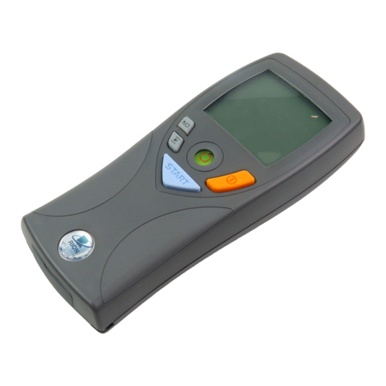
Page 22: Operation Key Panel
Controls and functions Operation key panel Rotor selector key Power key Level gauge Back light START key ON/OFF key (Measurement start/stop) - Page 23 Controls and functions Power key Turns power to the unit on and off. The key must be held for at least 1 second to take effect. START key Press to start or stop the measurement. Back light ON/OFF key Turns the backlight on and off. The backlight is automatically turned off when there is no key activity for a certain period.
-
Page 24: Preparations
Preparations Power Supply Using an AC Adapter (Option) To power the unit from an AC adapter, plug the output cable from the adapter into the DC IN jack on the viscotester and plug the AC adapter into an AC outlet rated for 100 V to 240 V AC. Caution To prevent the risk of electric shock, always connect the adapter output cable to the... - Page 25 Preparations DC IN jack AC adapter VA-05J Open the bottom cover To AC outlet, 100 V to 240 V AC, 50/60 Hz...
- Page 26 Preparations Using Batteries Alkaline battery (ALKALINE)- When operating the unit on battery Nickel-metal hydride rechargeable battery power, be sure to set the selector switch (NI-MH) selector switch inside the battery compartment to the correct position for the type of batteries in use (alkaline batteries or nickel-metal hydride rechargeable batteries)
- Page 27 Preparations Checking the battery voltage During viscosity measurement, check the battery status on the display. The num- ber of black segments will decrease as the batteries get used up (4 steps). When battery status indicator is down to 1 segment: Replace the batteries as early as possible with a fresh set.
- Page 28 Preparations Inserting the batteries 1. Remove the battery compartment lid as shown below. 2. Insert four IEC LR6, size AA batteries, paying attention to the polar- ity as shown below. 3. Replace the cover. Battery compartment Push Push the latch in the arrow direction and then lift up Caution to open the lid...
-
Page 29: Attaching The Rotor And Cup (Vt-05)
Preparations Attaching the Rotor and Cup (VT-05) Select a suitable rotor for the viscosity of the sample fl uid (see page 25), and insert the rotor into the cup. Taking care that the rotor does not fall out, raise the cup, engage the oval hole in the handle on the cup mounting pin of the main unit, and rotate it to the right to lock. - Page 30 Preparations Note • If you do not know the viscosity of the sample fl uid, perform measurement using rotors in the following order: No. 3 rotor, No. 5 rotor, No. 4 rotor. • Because this is a left-hand (reverse) screw thread, you must turn the rotor counterclockwise to screw it in.
-
Page 31: Attaching The Rotor (Vt-06)
Preparations Attaching the Rotor (VT-06) Select a suitable rotor for the viscosity of the sample fl uid (see page 29), and screw the rotor into the rotor mounting shaft. Note • If you do not know the viscosity of the sample fl uid, perform measurement using rotors in the following order: No. -
Page 32: Preparing The Sample Fluid
Preparations Preparing the Sample Fluid VT-05 When using cup A (no cutout), fi ll the cup with sample fl uid to the upper brim. When using cup B (with cutout), insert the cup into the sample fl uid up to the upper brim. For both cups A and B, the indication of the sample amount is about 460 mL. - Page 33 Preparations Note Adjust the volume of the sample fl uid so that it does not overfl ow when the rotor is inserted in the cup or beaker. When measuring fl uid with a low viscosity, the fl uid may spill when the rotor is activated. Adjust the fl uid fi rst to a suitable level.
-
Page 34: Measurement
Measurement 1. Hold the viscotester in one hand or mount it to the optional stand (VA-04). Use the level gauge on the unit to verify that the unit is ap- proximately horizontal. Fluid mark 2. Place the rotor in the center of the cup or beaker and fi ll in sample fl uid so that it comes to about the center of the fl uid mark on the rotor. - Page 35 Measurement 5. Press the START key. The indication “RUN” appears on the display and the rotor starts to turn. Hold the unit steady until the viscosity indication has stabilized. When a stable value has been obtained, press the START key again. The rotor stops turning, and the measurement value remains on the display for easy reading.
- Page 36 Measurement Important If the measurement value is below the mea- surement range for the respective rotor, the indication “UNDER” will be shown in the left part of the display under the bar graph. If the measurement value exceeds the measurement range, the indication “OVER”...
- Page 37 - Measurement time 100 seconds per measure- ment - Sample fl uid viscosity near maximum of respec- tive rotor measurement range Battery life: VT-05 approx. 600 measurements VT-06 approx. 300 measurements The unit cannot be shut the power off by the power...
-
Page 38: Applied Part
Applied part Rotor extension (only for VT-06) The supplied foldable rotor extension consists of three 30 cm rods joined by rings. The combined length is 90 cm. When wishing to use the extension at a length of 30 cm or 60 cm, open the connector rings with a pair of pliers, remove the desired number of elements, and rejoin the extension rods. -
Page 39: Specifi Cations
Specifi cations VT-05 Measurement range No. 4 rotor: 2 to 33 mPa•s (resolution: 0.1) No. 5 rotor: 15 to 150 mPa•s (resolution: 1) No. 3 rotor: 50 to 300 mPa•s (resolution: 1) Sample fl uid capacity Approx. 460 mL (With supplied accessories cup A or cup B) Measurement accuracy Within ±5% of each rotor’s maximum measurement... - Page 40 Specifi cations Max. continuous measurement time per measurement 100 s Display value hold function Value at end of measurement is retained Backlight function Switchable backlight Time until auto-off: 60 s (when rotor is not operating and unit is powered from batteries) Auto shutdown function (when an AC adapter is not used) If rotor is not turning and no controls are operated for 5 minutes, power is automatically shut off...
- Page 41 Specifi cations Power requirements Alkaline batteries LR6, Ni-MH rechargeable batteries, or AC adapter VA-05J (5 V to 7 V : rated voltage 6 V) Current consumption approx. 150 mA (at maximum torque) Battery voltage check Displaying battery status (4 steps) Dimensions 175 (H) ×...
- Page 42 Specifi cations Supplied accessories No. 3 rotor (dia. 45 × 47 × 160 mm) SUS304 No. 4 rotor (dia. 78 × 46 × 159 mm) A1050 (alumite) No. 5 rotor (dia. 61.2 × 36 × 149 mm) A1050 (alumite) Cup A (no cutout) (dia. 92 × 76 mm) A1050 (alumite) Cup B (with cutout) (dia.
- Page 43 Specifi cations VT-06 Measurement range (based on combination with the cup specifi ed below “Sample fl uid capacity”) No. 3 rotor: 0.3 to 13 dPa•s (resolution: 0.1) No. 1 rotor: 3 to 150 dPa•s (resolution: 1) No. 2 rotor: 100 to 4000 dPa•s (resolution: 10) Sample fl uid capacity No.
- Page 44 Specifi cations Reproducibility ±5% * Calibrated according to JIS Z 8809:2011 standard liquids for calibrating viscometer * The rounding error resulting from resolution occurs Rotor speed 62.5 rpm Max. continuous measurement time per measurement 100 s Display value hold function Value at end of measurement is retained Backlight function Switchable backlight...
- Page 45 Specifi cations Auto shutdown function (when an AC adapter is not used) If rotor is not turning and no controls are operated for 5 minutes, power is automatically shut off Resume function Last selected rotor number setting is retained during power-off Ambient conditions for use 5°C to 35°C, 10% to 90%RH (no condensation)
- Page 46 Specifi cations Supplied accessories No. 1 rotor (dia. 24 × 53 × 166 mm) SUS304 No. 2 rotor (dia. 15 × 1 × 113 mm) SUS304 No. 3 rotor (dia. 45 × 47 × 160 mm) SUS304 No. 3 Cup (dia. 52.6 × 75 mm) SUS304 Rotor extension (in a tube) (900 mm;...
- Page 47 Specifi cations Unit: mm Dimensional Drawings...
- Page 48 Distributor RION CO., LTD. 3-20-41 Higashimotomachi, Kokubunji, Tokyo 185-8533, Japan Manufacturer KYOSAITECHNOS CO., LTD. KORIYAMA OFFICE 214 Doba, Kooriyama City, Fukushima 963-8824, Japan No. 58610 13-10 Printed in Japan...
Need help?
Do you have a question about the VT-05 and is the answer not in the manual?
Questions and answers