
Related Manuals for Rion VM-56


Summary of Contents for Rion VM-56
- Page 1 INSTRUCTION MANUAL Tri-axial Groundborne Vibration Meter VM-56 3-20-41 Higashimotomachi, Kokubunji, Tokyo 185-8533, Japan http://www.rion.co.jp/english/...
- Page 3 Organization of this manual This manual describes the features, operation and other aspects of the Tri-axial Groundborne Vibration Meter VM-56. If the unit is used together with other equip- ment to confi gure a measurement system, consult the documentation of all other components as well.
- Page 4 Output Connectors Explains the input and output connectors of the unit. Default Settings Lists the factory default settings of the unit. Setup Files Explains how to start up the unit using settings saved in a setup fi le. Optional Accessories Explains how to use the optional extension cord with the unit.
-
Page 5: For Safety
FOR SAFETY In this manual, important safety instructions are specially marked as shown below. To prevent the risk of death or injury to persons and severe damage to the unit or peripheral equipment, make sure that all instructions are fully understood and observed. - Page 6 Precautions Operate the unit only as described in this manual. Take care not to drop the unit, and protect it from shocks and vibrations. Take care not to drop the vibration meter, and protect it from shocks. Ambient conditions for operation of the unit are as follows: temperature range −20°C to +50°C, relative humidity up to 90%RH.
- Page 7 In order to maintain the “water and dust resistant performance” of the unit, observe the following precautions. Make sure that the battery compartment lid, the side cover and the top cover of the unit are fi rmly closed. Do not open the battery compartment lid while the unit is wet. Do not leave the unit in a wet state.
-
Page 8: Precautions For Opening The Case
Precautions for opening the case Before opening the case and removing any equipment, place the case on sturdy, fl at table or on the fl oor. Then open the case fully as shown below. Never open the case while it is standing upright. - Page 9 This product can be used in any areas including residential areas. To conform to the EU requirement of the Directive on Waste Electrical and Electronic Equipment, the symbol mark on the right is shown on the instrument.
-
Page 10: Table Of Contents
Contents FOR SAFETY ................iii Precautions for opening the case ...........vi Outline ....................1 Controls and features ..............3 Front view ..................3 Right side view ................7 Top view ..................9 Bottom view ................10 Vibration Pickup and extension cord ........11 Preparations ..................12 Power ..................12 Power on/off ................ - Page 11 Display / I/O ...............53 Save ..................55 Option ................56 Measure ................57 Recall .................59 Measurement ................. 61 Manual mode ................61 Auto mode ................61 Timer Auto mode ..............62 Procedure example of the measurement ........63 Comparator ...................64 Store operation ................66 About the store data format ............66 About SD memory cards ............67 Data recovery................68 Formatting an SD memory card ..........68...
- Page 12 (typical characteristics) ............147 Non-weighting frequency response characteristics (typical characteristics) ............148 PV-83D frequency response characteristics ......148 VM-56+PV-83D Frequency response characteristics ....149 Velocity frequency response characteristics ......150 Displacement frequency response characteristics ....154 DIN plate frequency response characteristics ......155 L-bracket frequency response characteristics ......
-
Page 13: Outline
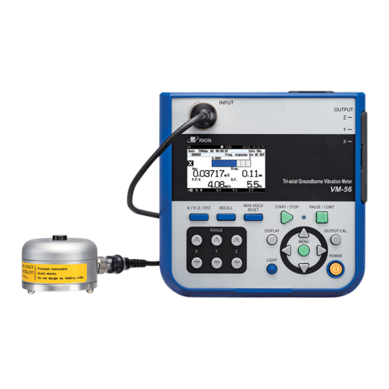
(USB, RS-232C). The VM-56 consists of the main unit and Vibration Pickup PV-83D. Hence the system processes 3 channels of vibration signal, and allows real-time analysis of each channels. Waveform recording as PCM format WAVE fi les on SD memory card will be available if the WR program option is installed, and recorded WAVE fi les make it easy to analyze later on a computer. - Page 14 Outline Block diagram...
-
Page 15: Controls And Features
Controls and features Front view INPUT connector Display Control section INPUT connector The Vibration Pickup PV-83D is to be connected here. If the vibration pickup is to be installed at a greater distance, optional extension cord can also be used. Display The display of the unit is a backlight LCD panel. - Page 16 Controls and features Control section MAX HOLD RESET key START/STOP key RECALL key Indicator LED X/Y/Z/XYZ key PAUSE/CONT key OUTPUT CAL key RANGE key POWER key MENU/ENTER key DISPLAY key LIGHT key RANGE keys These keys control the level range for the X, Y, Z axis. key switches the level range up, and the key switches the level range down.
- Page 17 Controls and features Indicator LED Lights/fl ashes in red or blue to indicate the operation or status of the unit. PAUSE/CONT key Press the key to pause measurement (processing), and press the key again to resume measurement (processing). During pause in manual processing, the indicator LED fl ashes in blue. Note The PAUSE key does not function while the store mode is Auto or Timer Auto.
- Page 18 Controls and features DISPLAY key This key switches measurement screen display. Each push of the key cycles through the settings in the following order: Measurement screen Max Hold screen Processed data screen Time-level screen Measurement screen Key lock Pressing the keys together activates the key lock.
-
Page 19: Right Side View
Controls and features Right side view OUTPUT connectors I/O connector Side cover USB connector DC IN connector Side cover This cover protects the connectors on the right side during transport or storage. Removing the cover gives access to the connectors shown above. Important To keep the water and dust resistant performance, close tightly the side cover of the unit. - Page 20 Controls and features USB connector (mini B) Serves for connection to a computer. DC IN connector The optional AC adapter NC-98 series can be connected here for powering the unit from an AC outlet (100 V to 240 V AC ). Important To prevent the risk of damage, do not use any AC adapter and battery pack other than the...
-
Page 21: Top View
Controls and features Top view Top cover SD card slot Top cover This cover protects the connectors on the top during transport or storage. Removing the cover gives access to the connectors shown above. Important To keep the water and dust resistant performance, close tightly the top cover of the unit. -
Page 22: Bottom View
Controls and features Bottom view Battery compartment Battery compartment Eight batteries (IEC LR, size AA) are inserted here. The [power-on mode] switch is in the battery compartment (see page 17). -
Page 23: Vibration Pickup And Extension Cord
Controls and features Vibration Pickup and extension cord For measurement, the Vibration Pickup PV-83D is required. Connect the Vibration Pickup PV-83D connector directly to the main unit INPUT connector. For more information, see the section on Vibration Pickup placement and connection in “Preparations” on page 18. This vibration pickup measures acceleration. -
Page 24: Preparations
Preparations Power The unit can be powered by eight IEC LR6, HR6, size AA batteries (alkaline, rechargeable nickel metal-hydride), and the optional AC adapter NC-98 Series. Rechargeable nickel metal-hydride batteries can be used, but the unit does not have a facility for charging the batteries. WARNING If the unit is heated during use or the unit produces smoke or smell of burning,... - Page 25 Preparations Inserting the batteries 1. Remove the battery compartment lid as shown below. 2. Insert eight IEC LR6, size AA batteries, paying attention to the po- larity as indicated in the compartment. 3. Replace the cover. IEC LR6 (sizeAA) battery × 8 Caution Take care not to reverse the (+) and (−) po- larity when inserting the batteries.
- Page 26 Preparations Important The rechargeable nickel metal-hydride battery is not charged by the VM-56. Select the used battery type by the [System] on the menu list screen (see page 47). Note The life of rechargeable nickel metal-hydride battery depends on the battery type and charge condition.
- Page 27 Preparations AC adapter To operate the unit with the AC adapter, connect it as shown below. Important To prevent the risk of damage, do not use any AC adapter other than the NC-98 series. DC IN connector OUTPUT AC adapter NC-98 series Open the side cover To AC outlet, 100 V to 240 V, 50/60 Hz Backup battery...
-
Page 28: Power On/Off
Preparations Power on/off To turn the unit on Hold down the POWER key until the power-on screen appears (at least 2 seconds). When the screen is shown, release the POWER key. After the unit has been started, the measurement screen appears. During start up, the indicator LED fl ashes red blue Indicator LED... - Page 29 Preparations Power-on mode switch Opening the battery compartment as shown below gives access to a switch labeled “A-B”. Normally the “A” position is used. Setting this switch to the ‘’B’’ position allows the unit to be turned on simply by supplying power to the DC IN connector.
-
Page 30: Vibration Pickup Placement And Connection
Preparations Vibration pickup placement and connection Vibration axis Environmental vibrations are normally measured in two horizontal planes (front/back and left/right) and one vertical plane. This means that complex vibration phenomena are reduced to three axes (X, Y, Z), for easier observation. The axes are defi ned as follows (facing the vibration source). - Page 31 Preparations Vibration Pickup placement Install the sensor on a solid horizontal plane. As necessary, fasten the sensor with bolts on the vibrating surface. Important Avoid locations exposed to direct sunlight or to drastic temperature changes. Such condi- tions can cause changes in Vibration pickup sensitivity, which will impair the accuracy of measurement results.
- Page 32 Preparations Important Never suspend the vibration pickup by its cord or pull at the cord. Otherwise cord breaks may occur.
- Page 33 Otherwise cord breaks due to twisting may occur. Do not connect to reel EC-04S Do not connect to Input Do not connect to vibration pickup cord connector on VM-56...
- Page 34 Preparations VIBRATION PICKUP PV-83D Optional extension cord can be connected here. EC-04B (10 m) EC-04D (50 m; with reel) EC-04E (100 m; with reel) Input connector When a cord reel is used, the EC-04S (5 m) must also be connected. (see page 81)
-
Page 35: Sd Memory Card And Program Cards
If the SD memory card is removed while data is being read or written to the card, the data may be destroyed. Use SD memory cards provided by Rion. The performance of other cards is not guaranteed. Note that we assume no responsibility for any damage or loss of stored measurement data. -
Page 36: Connection To A Data Recorder (Da-21), And Other Device
Connection to a data recorder (DA-21), and other device Connect the OUTPUT connector on the right side of the VM-56 with an in- put connector of data recorder (DA-21 and other device), using the optional BNC - Pin output cord CC-24 as shown below. The performance of other cables is not guaranteed. -
Page 37: Connection To A Computer
Preparations Connection to a computer Connect the USB connector on the right side of the VM-56 with a USB connector of a computer, using the optional (generic) A - mini B USB cable as shown below. An SD memory card inserted in the unit will be recognized as a removable disk by the computer when connected via USB, without having to install a USB driver. -
Page 38: Setting The Date And Time
Preparations Setting the date and time The unit incorporates a clock which allows recording the date and time along with measurement data. Set the date and time as described below. 1. Press the MENU/ENTER key to bring up the menu list screen. 2. - Page 39 Preparations System screen Clock settings screen...
-
Page 40: Measurement In A Dark Location
Preparations Measurement in a dark location Pressing the LIGHT key will turn on the display backlight, for easier reading in a dark location. The backlight operation pattern can be controlled via a menu, as follows. 1. Press the MENU/ENTER key to bring up the menu list screen. 2. - Page 41 Preparations System screen Backlight/LCD settings screen...
-
Page 42: Eco Setting (Power-Saving Mode)
Preparations Eco setting (Power-saving mode) The Eco setting enables the power saving feature. A long-time measurement can be performed using batteries only. 1. Press the MENU/ENTER key to bring up the menu list screen. 2. Use the keys to select [System] and press the MENU/ ENTER key. - Page 43 Preparations System screen Execution confi rmation screen...
-
Page 44: Calibration
Preparations Calibration When using external equipment to record measurement data, level calibration should be performed as follows. 1. Press the MENU/ENTER key to bring up the menu list screen. 2. Use the keys to select [Display / I/O] and press the MENU/EN- TER key. - Page 45 Preparations 6. Press the START/STOP key to return to the measurement screen. 7. Press the OUTPUT CAL key. The display switches to calibration indication. Verify that the measure- ment value reading is the same as the maximum val- ue for the range in each axis (X, Y, Z).
-
Page 46: Reading The Display
Reading the Display Measurement screen display The illustration below shows all elements of the display for explanation purposes. In actual operation, such a screen will not be shown. (In case of 1 channel screen indication,) indication... - Page 47 Reading the Display Mode of analysis Indicates the condition of the display screen. Measurement time/Total measurement time When the store mode is Manual, the measurement time is displayed. When the store mode is Auto, the total measurement time is displayed Comparator Display when comparator is set (see page 53) Operation/measurement elapsed time...
- Page 48 Reading the Display Bar graph range Shows the upper and lower limit of the bar graph. The range can be changed using the RANGE key on the control section. Overload indication When a signal overload condition of the acceleration value is detected, the indication (white on black) is shown for at least 8 second.
- Page 49 Reading the Display Key lock Indicates that the key lock function has been set to ON (see page 6). Backlight Indicates that the display backlight has been light up (see page 28). If the remaining battery capacity indication or the power supply plug symbol is shown in red, the backlight will not come on.
- Page 50 Reading the Display Measurement in progress symbol When a measurement is in progress, the symbol fl ashes. The indicator LED also fl ashes in red. During auto store, the symbol also fl ashes. The indicator LED fl ashes in red. During measurement standby, the symbol is shown.
-
Page 51: Measurement Screen
Reading the Display Measurement screen When the measurement screen is displayed. Measurement screen (3 channels display) When the measurement screen is displayed, pressing the X/Y/Z/XYZ key changes the channel display as shown below. -
Page 52: Max Hold Display Screen
Reading the Display Max Hold display screen When the measurement screen is displayed, pressing the DISPLAY key brings up the Max Hold display screen as shown below. Pressing the X/Y/Z/XYZ key switches the vibration axis (channel) to be shown on the display. Pressing the MAX HOLD RESET key resets the value of the max hold function. -
Page 53: Processed Data Display Screen
Reading the Display Processed data display screen When the Max Hold display screen is displayed, pressing the DISPLAY key brings up the processed data display screen as shown below. Pressing the X/Y/Z/XYZ key switches the vibration axis (channel) to be shown on the display. - Page 54 Reading the Display 1 channel display 3 channel display...
-
Page 55: Time-Level Display Screen
Reading the Display Time-level display screen When the processed data display screen is displayed, pressing the DISPLAY key brings up the time-level display screen as shown below. Pressing the X/Y/Z/XYZ key switches the vibration axis (channel) to be shown on the display. 1 channel display 3 channel display... -
Page 56: Indicator Messages
Reading the Display Indicator messages After the power is turned on, a message is displayed as shown below. POWER key is pushed, until about 1 minute 30 seconds have elapsed since startup. When keys such as START/STOP is pressed, indicator messages such as shown below will appear on the display for about 1 second. -
Page 57: Menu List Screen
Reading the Display Menu list screen When the measurement screen is displayed, pressing the MENU/ENTER key brings up the menu list screen as shown below. Use the keys to select the desired menu and press the MENU/ ENTER key. Pressing the PAUSE/CONT key or the START/STOP key switches back to the measurement screen. -
Page 58: System
Reading the Display System This screen sets the item concerning the system of the unit. Use the keys to select [System] and press the MENU/ENTER key. The system screen appears. Each item of the system screen is selected using the key. - Page 59 Reading the Display Battery Type Displays the screen to select the type of battery used for the unit. The battery power corresponding to the selected battery is displayed on the measurement screen. Select [Battery type] and press the MENU/ENTER key. The battery type screen appears.
- Page 60 Reading the Display Index Displays the screen to set the identifi cation number of the unit when multiple units are used in a parallel measurement. Select [Index] and press the MENU/ENTER key. The index screen appears. Use the keys to select the digit, and use the keys to set the value (1 to 255).
-
Page 61: Store
Reading the Display Store This screen sets the mode that stores the operation result data. Use the keys to select [Store] and press the MENU/ENTER key. The store screen appears. Each item of the store screen is selected using the key. - Page 62 Reading the Display Store Mode Displays the screen to select the store mode. Select [Store Mode] and press the MENU/ENTER key. The store mode setting screen appears. Use the keys to select the store mode (Manual, Auto, Timer Auto) and press the MENU/ENTER key. Store Name (common to each mode) Displays the screen to set the identifi cation number of the store data (0000 to 9999).
- Page 63 Reading the Display Total Measurement Time (Auto mode) Displays the screen to select the total measurement time in the auto mode. Select [Total Measurement Time] and press the MENU/ENTER key. The total measurement time screen appears. User setting (Manual mode and Auto mode) When [Manual] is selected from [Measurement Time] of the Manual mode or [Total Measurement Time] of the Auto mode, the user setting items will be displayed and measurement time can be set arbitrarily.
- Page 64 Reading the Display Timer Auto Stop (Timer Auto mode) Displays the screen to set the measurement stop time in the Timer Auto mode. Select [Stop] and press the MENU/ENTER key. The stop time setting screen appears. Timer Auto Interval (Timer Auto mode) Displays the screen to select the timer auto interval in the Timer Auto mode.
-
Page 65: Display / I/O
Reading the Display Display / I/O This screen sets the type of output signal etc. Use the keys to select [Display / I/O] and press the MENU/ ENTER key. The display / I/O screen appears. Each item of the display / I/O screen is selected using the key. - Page 66 Reading the Display Communication Interface Displays the screen to select a type of communication with a computer or printer to be connected to the unit. Select [Communication Interface] and press the MENU/ENTER key. The communication interface screen appears. Use the keys to select the communication type (OFF, USB, RS-232C) and press the MENU/ENTER key.
-
Page 67: Save
Reading the Display Save Use the keys to select [Save] and press the MENU/ENTER key. The save screen appears. Each item of the save screen is selected using the key. Screenshot (BMP) Saves the displayed measurement screen to the internal memory in BMP (bitmap) format. -
Page 68: Option
Reading the Display Option This screen switches the function from the unit to each program when an optional program is installed. Use the keys to select [Option] and press the MENU/ENTER key. The option screen appears. Each item of the switch function screen is selected using the key. -
Page 69: Measure
Reading the Display Measure This screen sets frequency weighting and the delay time. The setting items of Measure are different in Standard and SBR of Standard setting respectively. Use the keys to select [Measure] and press the MENU/ENTER key. The measurement setting screen appears. Pressing the PAUSE/CONT key switches back to the menu list screen. - Page 70 Reading the Display Dominant Frequency Setting for determining the dominant frequency. In accordance with the type of building vibration to be measured, calculate the frequency with the highest spectrum from the ratio of the dominant frequency calculated from measured PPV and the regulated value specifi ed in DIN 4150-3 as the dominant frequency.
-
Page 71: Recall
If a data fi le saved on a computer is copied or ma- nipulated, and the copied fi le is then loaded back into the VM-56, the displayed measurement date and time may not match the actual time stamp of... - Page 72 Reading the Display MENU list items System Read/Save Setup File [v]--------Load Default Settings Internal Memory---- List of setting groups on internal memory SD---- Startup File Clock Settings Backlight/LCD Settings [v]-----Backlight Auto Off Backlight brightness LCD Auto Off (Auto Store) Battery Type---- Alkaline / Ni-MH Card Format Index Program Information [v]--------Model, Version...
-
Page 73: Measurement
Measurement On this unit, PPV, VDV, and other values are calculated at one time. The calculation results are saved in an SD card. Via the Store menu, you can select the following three Store modes. Manual mode This mode allows calculation during a preset “Measurement Time.” Instan- taneous values are not saved. -
Page 74: Timer Auto Mode
Measurement Timer Auto mode With this mode, you can set the measurement start time and the measurement end time to perform measurement between these times. By setting a “Timer Auto Interval,” you can perform, for example, a 10-minute measurement ev- ery hour. -
Page 75: Procedure Example Of The Measurement
Measurement Procedure example of the measurement (1) Check that an SD card is inserted into the unit. Then, press the POWER key to start the unit. (2) Press the MENU/ENTER key. The menu list screen appears. As necessary, set the time and other parameters. (3) On the menu list screen, select the Store menu, and then set the Store modes. -
Page 76: Comparator
Comparator The comparator function compares the PPV (peak particle velocity) of the signal from the vibration pickup to a limit value that has been set previously. When the signal is equal to or higher than the limit value, an output (open collector circuit, LCD indication) is activated. - Page 77 Comparate Example: To achieve operation as shown in the diagram below, make the settings as follows. Set “Node Number” to “4” and create Line 1 in accordance with DIN 4150-3. Set “Limit Node 1” to ①, “Limit Node 2” to ②, “Limit Node 3” to ③, and “Limit Node 4”...
-
Page 78: Store Operation
The store name specifi ed on the menu screen is created as a 4-digit number under the subdirectory name. The fi le of one per one address is made. VM-56 VM_001_VM_MANU_0123_0000.rnd Manual_0000 Partitioned file Store mode VM_001_VM_MANU_0000_0000.rnd... -
Page 79: About Sd Memory Cards
For this reason, be sure to use only the SD memory cards for VM-56 provided by Rion. The performance of other cards is not guaranteed. -
Page 80: Data Recovery
Formatting on a computer cannot recover the data. However, please note that the recovery of all data is not guaranteed. Modifi ed data cannot be displayed with the recall function of the VM-56. Such data must be checked on a computer. -
Page 81: Screen Hard Copy
DISPLAY key, the “Screenshot was saved to the card” message is displayed and the current screen contents will be saved as a bitmap fi le on the SD memory card. Store target folder: VM-56\Screenshot\ File name: Time at which the fi le was stored File name extension: .BMP... -
Page 82: Card Capacity And Store Time
Card capacity and store time The measurement duration for which data can be stored on an SD memory card depends on the capacity of the inserted card. Approximate times are listed below. Using Auto store Only Inst. store interval set SD memory card capacity 512 MB 2 GB... -
Page 83: When Performing Waveform Recording
Card capacity and store time When performing waveform recording Using Auto store, Inst. store interval 1 s, measurement channel XYZ SD memory card capacity 512 MB 2 GB 32 GB Approx. Approx. Approx. 16 bit 8 hours 32 hours 698 hours Approx. -
Page 84: Output Connectors
Output Connectors OUTPUT connector This turns the AC output signal ON/OFF and makes the settings for the signal. 1. Press the MENU/ENTER key to open the menu list screen. 2. Select the Display/I/O menu. 3. Positioning the cursor on “Output,” press the MENU/ENTER key. - Page 85 Output Connectors 4. As necessary, switch “Output” ON/OFF. If you don’t need an AC output, select OFF. If you select ON, then follow steps 5 and 6 below. 5. For “Quantity,” select between “Acc.” (Acceleration) and “Vel.” (Ve- locity). 6. To output the frequency-weighted signal, select “Weighted.” To output the non-frequency-weighted signal, select “not-Weighted.”...
- Page 86 Output Connectors AC output characteristic Output voltage: 1 Vrms (at Range Upper) at Acc. 0.1 Vrms (at Range Upper) at Vel. Output impedance: 600 Ω Load impedance: 10 kΩ or more Suitable cable: Output cord CC-24 (BNC - mini plug cable) The performance of other cables is not guar- anteed.
-
Page 87: Default Settings
Default Settings The factory default settings of the unit are listed below. Displayed channel .............. Z axis Range ................. 0.001 m/s to 10 m/s Backlight auto off .............. 30 s Backlight brightness............2 LCD auto off at auto store ..........OFF Battery type ............... -
Page 88: Setup Files
Setup Files Resume function When power to the unit is turned on, the measurement screen appears. The settings active at this point are the same as were selected before the unit was last turned off (resume function). Note When the unit is started while a start up fi le exists on the inserted SD memory card, the start up fi le load function (see the following description) will be executed fi rst. -
Page 89: Restoring Default Settings (Factory Default Settings)
Setup Files Restoring default settings (factory default settings) Follow the steps below to restore the default settings. 1. Use the keys to select [System] and press the MENU/ ENTER key. The system screen appears. 2. Use the keys to select [Read/Save setting] and press the MENU/ ENTER key. -
Page 90: Using Setup Fi Les
Setup Files Using setup fi les Setup fi les enable the following functions. • Establish settings quickly and precisely by loading from a fi le prepared beforehand and stored on internal memory • Return settings that were accidentally changed to the previous condition by loading from a fi le stored on internal memory Setup fi les can be saved up to fi ve in the internal memory of the unit. - Page 91 Setup Files Loading a setup fi le Note When you load settings from a fi le, the current settings will be overwritten. If necessary, you should save the current settings before loading a new set of settings. 1. Use the keys to select [System] and press the MENU/ ENTER key.
-
Page 92: Setting A Start Up Fi Le
Setup Files Setting a start up fi le When a setting is saved in a start up fi le, the unit can be started using the setting. 1. Set the unit to the intended condition, so that measurement param- eters and other settings are as desired. 2. -
Page 93: Optional Accessories
The 30 m, 50 m, and 100 m cable is supplied on a reel. Extension cords with reels can be joined. * Extension cords without reel cannot be joined. Extension cords with reels Vibration pickup EC-04S cord supplied with VM-56 (5m) VM-56 Disconnect from vibration pickup cord... - Page 94 When installing or dismantling a system, always make sure that all connection cords are dis- connected from the cord reel. Otherwise cord breaks due to twisting may occur. Disconnect from reel EC-04S Disconnect from Input connector Disconnect from vibration pickup cord on VM-56...
-
Page 95: Serial Interface
It is also possible to send measurement results (current results as well as data stored in the memory of the VM-56) to the computer for further processing. Standard terminal software (Hyper Terminal, etc.) can also be used as com- munication client. - Page 96 Serial Interface Setting of the VM-56 when using the RS-232C When using RS-232C, set the communication interface for the VM-56 fol- lowing the steps below. 1. Press the MENU/ENTER key to bring up the menu list screen. 2. Use the keys to select [Display / I/O] and press the MENU/ENTER key.
- Page 97 The cable is optional. Shield VM-56 Computer I/O connector Note When VM-56 is connected to a computer, the min- imum measurement level of VM-56 may rise by the noise from a computer. Transfer protocol Transfer principle: full duplex Sync principle:...
-
Page 98: Usb
Serial Interface About USB The VM-56 can use a USB connection for operation control and transfer of data. To use the USB interface, a USB driver must be installed on the computer. Please download USB driver from our web site (http://rion-sv.com/). - Page 99 To enable use of these functions, you must fi rst download driver software from the RION Corporation web site and install this driver on the computer to be used with the VM-56. The driver will create a virtual COM port on the computer.
- Page 100 Serial Interface Follow the wizard to complete the installation. Screens during installation are as follows.
- Page 101 Serial Interface Depending on your environment, [Windows Security] may be dis- played. Click on “Install” or “Continue”.
- Page 102 Serial Interface 2. Turn power to the VM-56 on, select [Display / I/O] and set [Com- munication Interface] to “USB”. Important The above steps must be completed before connecting the USB cable. 3. Connect the VM-56 to the computer with a USB cable (see page 87).
- Page 103 Serial Interface When the computer detects the VM-56, the device driver software installa- tion is started automatically. When the installation has been completed, USB communication is enabled. The driver installation creates a virtual COM port in the computer. For infor- mation on how to verify that the installation was successful, see the section “Checking the virtual COM port”...
- Page 104 Serial Interface Checking the virtual COM port 1. After installing the driver, set [Communication Interface] to “USB” at the VM-56 and connect the USB cable. 2. Open the Device Manager (“Hardware” tab under “Properties” in My Computer).
- Page 105 COM port name. If this is not shown, check the connection be- tween the VM-56 and the computer (step 1). If there is an “×” over the icon, the port is not functioning normally. Install the driver again.
-
Page 106: Connection To A Computer
Serial Interface Connection to a computer Connect the USB connector on the bottom of the VM-56 with a USB con- nector of a computer, using the optional (generic) A - mini B USB cable as shown below. Important Be sure to connect the cable only after selecting the [USB] setting. -
Page 107: Disconnection From The Computer
Disconnection from the computer VM-56 will be recognized as “removable media”. Consequently, the correct procedure as described below must be followed when disconnecting the VM-56. 1. Click on the “Safely remove hardware” icon in the right section of the taskbar, and select “Safely remove USB Mass Storage Device - Drive (*1)”. -
Page 108: Communication Cutoff
Communication cutoff Sleep mode When sleep mode is enabled, the unit enters the sleep state after the current block has been sent. In the sleep state, the VM-56 does not send or accept commands. ECO setting When ECO setting is selected, it will be enabled after a transmission of cur- rent command is completed. -
Page 109: Rated Values
Rated values Guaranteed values Case Rated Values Remarks Result code 0004 (state error) response VM-56 response time Max. 3 s if due to processing reasons Send character inter- Max. 100 ms − After receiving data from the VM-56, Interval until VM-56... -
Page 110: Command
There are two types of commands: setting commands and request commands. Setting command This type of command serves for changing the VM-56 status or mea- surement parameters. Only some commands of this type will produce a response from the VM-56. The response consists of status information returned after the setting command has been processed. - Page 111 Serial Interface Permitted items of setting command • Lower case may be used instead of upper case. • Upper case may be used instead of lower case. Setting command examples LCD Auto Off,Short[CR][LF] Valid Space after “,” may be omitted. lcd auto off, short [CR][LF] Command name in all lower Valid...
- Page 112 This is a response to the situation where the command (setting or 0004 request) cannot be executed in a current situation. Transfer codes The codes (control codes) used for communication with the VM-56 are as follows. Code Hex notation Meaning...
-
Page 113: Command List
Serial Interface Command list S: Setting command (command for making a VM-56 setting) R: Request command (command for obtaining status information or mea- surement data from VM-56) Communication Command Function See page Echo Echo back (S/R) ......106 Remote Control Remote mode (S/R) ...... - Page 114 Serial Interface Display Channel Setting Display channel setting (S/R) ..113 Max Hold Reset Max hold reset (S) ......113 Command Function See page OUTPUT Output setting (S/R) ...... 114 OUTPUT Quantity Output quantity (S/R) ..... 114 OUTPUT Band Output frequency characteristic (S/R) ..........
- Page 115 Serial Interface Measurement Time Manual (Unit) Measurement time of user setting on manual store (unit) (S/R) ... 121 Measurement Time Preset Auto Total measurement time of auto store (S/R) ......122 Measurement Time Auto (Num) Total measurement time of user setting on auto store (number) (S/R) ...
- Page 116 Serial Interface Acc Lower Frequency weighting of Acc lower (S/R) ..........129 Acc Upper Frequency weighting of Acc upper (S/R) ..........129 Vel Disp Build Lower Frequency weighting of building Vel and Disp lower (S/R) ....... 129 Vel Disp Build Upper Frequency weighting of building Vel and Disp upper (S/R) ......
- Page 117 Serial Interface Underrange Inst Z Zch underrange Inst (R) ....136 Underrange Calc Z Zch underrange Calc (R)) ....137 Overload Inst Z Zch overload Inst (R) ..... 137 Overload Calc Z Zch overload Calc (R) ....137 Data output Command Function See page...
-
Page 118: Command Description
Serial Interface Command description Communication Echo Echo back Setting ON/OFF of echo back Setting command Echo, p1 Parameter p1= “Off” p1= “On” Request command Echo? Response data Returned value Same as for setting command Remote Control Remote mode Setting ON/OFF of remote mode When remote mode is “On”, the key operation of the unit is invalid (only the POWER key and the LIGHT key are effective). -
Page 119: System
Serial Interface System System Version System version information Request system version information Request command System Version?p1 Parameter p1= “VM” p1= “WR” p1= “RT” Response data d1= “x.x” (x is 0 to 9) There is no setting command When the parameter p1 is omitted, the request command means “System Version?VM”... -
Page 120: Calibration
Serial Interface Calibration Calibration Transition to calibration state Setting command Calibration, p1 Parameter p1= “Off” p1= “On” Request command Calibration? Response data Returned value Same as for setting command Index Number Index number Setting index number Setting command Index Number, p1 Parameter p1= 1 to 255 Request command Index... -
Page 121: Load Default Factory Settings Load Default Factory Settings (S)
Serial Interface Backlight Backlight Setting ON/OFF of backlight Setting command Backlight, p1 Parameter p1= “Off” p1= “On” Request command Backlight? Response data Returned value Same as for setting command Backlight Auto Off Backlight auto off Setting time of backlight auto off Setting command Backlight Auto... -
Page 122: Lcd (S/R)
Serial Interface Setting ON/OFF of LCD Setting command LCD, p1 Parameter p1= “Off” p1= “On” Request command LCD? Response data Returned value Same as for setting command LCD Auto Off LCD auto off Setting time of LCD auto off Setting command Auto Off, p1 Parameter... -
Page 123: Battery Type (S/R)
Serial Interface Battery Type Battery type Setting battery type Setting command Battery Type, p1 Parameter p1= “Alkaline” p1= “Nickel” Request command Battery Type? Response data Returned value Same as for setting command SD Card Total Size SD memory card capacity Request capacity of SD memory card Request command SD Card... -
Page 124: Time Scale Of Time-Level Display (S/R)
Serial Interface Display, performance Time Level Time Scale Time scale of time-level display Setting time scale of time-level display Setting command Time Level Time Scale, p1 Parameter p1= “20s” p1= “1m” p1= “2m” Request command Time Level Time Scale? Response data Returned value Same as for setting command Range X... -
Page 125: Zch Range Upper Limit (S/R)
Serial Interface Range Z Zch range upper limit Setting of Z channel range Setting command Range Z, p1 Parameter p1= “1” p1= “10” Request command Range Response data Returned value Same as for setting command Display Channel Setting Display channel setting Setting of display channel Setting command Display... -
Page 126: Output Setting (S/R)
Serial Interface OUTPUT Output setting Setting signal output Setting command OUTPUT, p1 Parameter p1= “Off” p1= “On” Request command OUTPUT? Response data Returned value Same as for setting command OUTPUT Quantity Output quantity Setting output signal type Setting command OUTPUT Quantity, p1 Parameter p1= “Acc”... -
Page 127: Output Frequency Characteristic (S/R)
Serial Interface OUTPUT Band Output frequency characteristic Setting output frequency characteristic Setting command OUTPUT Band, p1 Parameter p1= “not-weighed” (In the case of Vel. : Building Damage) p1= “Interlock” (In the case of Vel. : Human Exposure) p1= “Selected frequency band” (only RT mode) Request command OUTPUT Band? -
Page 128: Comparator Node Frequency (S/R)
Serial Interface Comparator Node”x” Frequency Comparator node frequency Setting node”x” frequency setting Set frequency of xth node The value multiplied by 0.1 is set as the parameter Setting command Comparator Node ”x” Frequency, p1 Parameter p1= 5 to 3150 Request command Comparator Node ”x” Frequency? Response data Returned value Same as for setting command... -
Page 129: Rs-232C Baud Rate (S/R)
Serial Interface Baud Rate RS-232C baud rate Setting RS-232C baud rate Setting command Baud Rate, p1 Parameter p1= “38400” p1= “57600” p1= “115200” Request command Baud Rate? Response data Returned value Same as for setting command Communication Flow RS-232C communication fl ow Setting RS-232C Communication Flow Setting command Communication... -
Page 130: Store Mode (S/R)
Serial Interface Store Store Mode Store mode Setting store mode Setting command Store Mode, p1 Parameter p1= “Manual” p1= “Auto” p1= “Timer Auto” Request command Store Mode? Response data Returned value Same as for setting command Store Name Store name Setting store name Setting command Store... -
Page 131: Calculation Interval (S/R)
Serial Interface Calculation Interval Preset Calculation interval Setting calculation interval Setting command Calculation Interval Preset, p1 Parameter p1= “Off” p1= “10s” p1= “30s” p1= “1m” p1= “5m” p1= “10m” p1= “15m” p1= “30m” p1= “1h” p1= “8h” p1= “24h” p1= “Manual” (User setting) Request command Calculation Interval... -
Page 132: Calculation Interval Of User Setting (Unit) (S/R)
Serial Interface Calculation Interval (Unit) Calculation interval of user setting (unit) Setting time unit when “Calculation Interval Preset” command parameter is “Manual” Setting command Calculation Interval (Unit), p1 Parameter p1= “s” p1= “m” p1= “h” Request command Calculation Interval (Unit)? Response data Returned value Same as for setting command... -
Page 133: Measurement Time Of User Setting On Manual Store (Number) (S/R)
Serial Interface Measurement Time Manual (Num) Measurement time of user setting on manual store (number) Setting value when “Measurement Time Preset” command parameter is “Manual” on manual store mode Setting command Measurement Time Manual (Num), p1 Parameter p1= 1 to 59 (Time unit is s [second] or m [minute]) p1= 1 to 24 (Time unit is h [hour]) -
Page 134: Total Measurement Time Of Auto Store (S/R)
Serial Interface Measurement Time Preset Auto Total measurement time of auto store Setting total measurement time of the auto store mode Setting command Measurement Time Preset Auto, p1 Parameter p1= “10s” p1= “30s” p1= “1m” p1= “5m” p1= “10m” p1= “15m” p1= “30m”... -
Page 135: Total Measurement Time Of User Setting On Auto Store (Unit) (S/R)
Serial Interface Measurement Time Auto (Unit) Total measurement time of user setting on auto store (unit) Setting time unit when “Measurement Time Preset” command parameter is “Manual” on auto store mode Setting command Measurement Time Auto (Unit), p1 Parameter p1= “s” p1= “m”... -
Page 136: Timer Auto Stop Time (S/R)
Serial Interface Timer Auto Stop Time Timer auto stop time Setting timer auto stop time Setting command Timer Auto Stop Time, p1/p2/p3 p4:p5:p6 Parameter p1= 2018 or after (year) p2= 1 to 12 (month) p3= 1 to 31 (date) p4= 0 to 23 (hour) p5= 0 to 59 (minute) -
Page 137: Sleep Mode (S/R)
Serial Interface Sleep Mode Sleep mode Setting ON/OFF of sleep mode Setting command Sleep Mode, p1 Parameter p1= “Off” p1= “On” Request command Sleep Mode? Response data Returned value Same as for setting command Manual Address Manual store address Setting manual store address Setting command Manual Address, p1... -
Page 138: Pause (S/R)
Serial Interface Pause Pause Pause a measurement Setting command Pause, p1 Parameter p1= “Pause” p1= “Clear” Request command Pause? Response data Returned value Same as for setting command Manual Store Manual store Storing the calculated value in manual store Setting command Manual Store,, p1 Parameter... -
Page 139: Measurement (Operation) Stop Time (R)
Serial Interface Measurement Stop Time Measurement (operation) stop time Request measurement (operation) stop time Request command Measurement Stop Time? Response data d1/d2/d3 d4:d5:d6 Returned value d1= 2018 or after (year) d2= 1 to 12 (month) d3= 1 to 31 (date) d4= 0 to 23 (hour) d5= 0 to 59... -
Page 140: Frequency Weighting Of Y-Axis For Acceleration (S/R)
Serial Interface Acc Weighted Y Frequency weighting of Y-axis for acceleration Setting Frequency weighting of Y for Acc. Setting command Weighted Y, p1 Parameter p1= “Wm” p1= “Wb” p1= “Wd” p1= “Non-Weighting” Request command Acc Weighted Response data Returned value Same as for setting command Acc Weighted Z Frequency weighting of Z-axis for acceleration... -
Page 141: Frequency Weighting Of Acc Lower (S/R)
Serial Interface Acc Lower Frequency weighting of Acc lower Setting lower limit of frequency range for Acc. Setting command Lower, p1 Parameter p1= “0.5Hz” p1= “1Hz” p1= “4Hz” Request command Acc Lower? Response data Returned value Same as for setting command Acc Upper Frequency weighting of Acc upper Setting upper limit of frequency range for Acc. -
Page 142: Frequency Weighting Of Building Vel And Disp Upper (S/R)
Serial Interface Vel Disp Build Upper Frequency weighting of building Vel and Disp upper Setting upper limit of frequency range for Building damage Vel. and Disp. Setting command Disp Build Upper, p1 Parameter p1= “80Hz” p1= “100Hz” p1= “250Hz” p1=“Sensor Dependent” Request command Vel Disp Build... -
Page 143: Frequency Weighting Of Human Vel Upper (S/R)
Serial Interface Vel Human Upper Frequency weighting of human Vel upper Setting upper limit of frequency range for Human exposure Vel. Setting command Human Upper, p1 Parameter p1= “80Hz” p1= “100Hz” p1= “250Hz” p1=“Sensor Dependent” Request command Vel Human Upper? Response data Returned value Same as for setting command... -
Page 144: Frequency Weighting Of Acc Lower
Serial Interface SBR Acc Lower Frequency weighting of Acc lower (SBR Mode) HPF on unweighted Acc. on SBR mode Setting command Lower, p1 Parameter p1= “0.5Hz” p1= “1Hz” p1= “4Hz” Request command SBR Lower? Response data Returned value Same as for setting command SBR Acc Upper Frequency weighting of Acc upper (SBR Mode) LPF on unweighted Acc. -
Page 145: Line (Sbr Mode) (S/R)
Serial Interface SBR Dominant Frequency Line Determine for dominant frequency line (SBR Mode) Setting of Dominant Frequency Line (SBR Mode) Setting command Dominant Frequency Line, p1 Parameter p1= “No Line” p1= “Line1” p1= “Line2” p1=“Line3” Request command SBR Dominant Frequency Line? Response data Returned value... -
Page 146: Xch Underrange Inst (R)
Serial Interface Operation Underrange Inst X Xch underrange Inst Request presence of underrange Inst information of X channel Request command Underrange Inst Response data Returned value d1= “Off” (there is no information) d1= “On” (there is information) There is no setting command Underrange Calc X Xch underrange Calc Request presence of underrange information in processed data of X channel... -
Page 147: Xch Overload Calc (R)
Serial Interface Overload Calc X Xch overload Calc Request presence of overload information in processed data of X channel Request command Overload Calc Response data Returned value d1= “Off” (there is no information) d1= “On” (there is information) There is no setting command Underrange Inst Y Ych underrange Inst Request presence of underrange Inst information of Y channel... -
Page 148: Ych Overload Inst (R)
Serial Interface Overload Inst Y Ych overload Inst Request presence of overload Inst information of Y channel Request command Overload Inst Response data Returned value d1= “Off” (there is no information) d1= “On” (there is information) There is no setting command Overload Calc Y Ych overload Calc Request presence of overload information in processed data of Y channel... -
Page 149: Zch Underrange Calc (R))
Serial Interface Underrange Calc Z Zch underrange Calc Request presence of underrange information in processed data of Z channel Request command Underrange Calc Response data Returned value d1= “Off” (there is no information) d1= “On” (there is information) There is no setting command Overload Inst Z Zch overload Inst Request presence of overload Inst information of Z channel... -
Page 150: Output Displayed Value (R)
Serial Interface Data output Output displayed value Send the request command at one second interval or longer. Request command DOD? Response data d1,d2,...,d67 Returned value d1 = “xxx.x” Acc. of X channel (Inst value) d2 = “xxx.x” PPV of X channel (Inst value) d3 = “xxx.x”... -
Page 151: Output Calculation Value (R)
Serial Interface d20 = “xxx.x” KBFT or veff,max,30 of X channel (Calc value) (General Mode:KBFT value, SBR Mode: veff,max,30 value) d21 = 0 or 1 Calc Overload information (1: Yes, 0: No) d22 = 0 or 1 Calc Under-range information (1: Yes, 0: No) d23 to d44 : Y channel information... - Page 152 Serial Interface d9 = “xxx.x” D.F. of X channel (Max hold value) d10 = “xxx.x” Disp. of X channel (Max hold value) d11 = 0 or 1 Max hold Overload information (1: Yes, 0: No) d12 = 0 or 1 Max hold Under-range informa- tion (1: Yes, 0: No)
-
Page 153: Continuous Output (R)
Serial Interface Continuous output Data are sent periodically to the computer every 100 msec. To stop the data transfer, send the stop request transfer code <SUB> (hexa- decimal notation: 1AH). Request command DRD Response data d1,d2,...,d67 Returned value d1 = “xxx.x” Acc. - Page 154 Serial Interface d19 = “xxx.x” VDV of X channel (Calc value) d20 = “xxx.x” KBFT or veff,max,30 of X chan- nel (Calc value) (General Mode:KBFT value , SBR Mode: veff,max,30 value) d21 = 0 or 1 Calc Overload information (1: Yes, 0: No) d22 = 0 or 1 Calc Under-range information (1: Yes, 0: No)
-
Page 155: Command Example
Serial Interface Command example The example of a setting by a command is shown. Using a request command after a setting is recommended. Basic setting Setting the time scale of time-level display to “20s” Time Level Time Scale, 20s Setting the level range upper limit of X channel, Y channel and Z channel to “10 m/s ”... - Page 156 Serial Interface When operating manual store Setting the Store Mode to “Manual” Store Mode, Manual Setting the Store Name to “0200” Store Name, 200 Setting the Measurement Time to “15min” Measurement Time Preset Auto, 15m Measurement start / stop Measure, Start Measure, Stop Saving of the store result Manual...
-
Page 157: Reference Information
+50°C Approx. 24 hours Approx. 24 hours Operating condition: • The PV-83D is connected to the VM-56 • Eco setting is ON • Inst. store interval is OFF • Calculation interval is 30 sec Keeping the backlight on the display screen turned on will shorten battery life by approximately 10% to 40%. -
Page 158: Input Connector
The following arrangement can be used to calibrate the vibration pickup with an exciter. • Sine wave signal oscillator • Power amplifi er DC-300A series II (Manufacturer:Crown) • Exciter VG-100 (Vertical-directionexciter) (Manufacturer:AR Brown) APS-129 (Horizontal-direction exciter) (Manufacturer:AR Brown) • Reference accelerometer PV-03 (Manufacturer:RION) • Vibration meter VM-83 (Manufacturer:RION) -
Page 159: Wm, Wb, Wd Frequency Response Characteristics (Typical Characteristics)
Reference Information Wm, Wb, Wd Frequency response characteristics (typical characteristics) Typical Wm and bandwidth limiting Wm response curves Wm bandwidth limiting compensation curve Wm compensation curve 1000 Frequency (Hz) Typical Wb and bandwidth limiting Wb response curves Wb bandwidth limiting compensation curve Wb compensation curve 1000... -
Page 160: Non-Weighting Frequency Response Characteristics (Typical Characteristics)
Reference Information Non-weighting frequency response characteristics (typical characteristics) Upper limit: Sensor dependent Upper limit:250 Hz Lower limit:0.5 Hz Upper limit:100 Hz Lower limit:1.0 Hz Upper limit:80 Hz Lower limit:4.0 Hz 1000 Frequency (Hz) PV-83D frequency response characteristics The PV-83D is a vibration pickup that converts acceleration into an electrical signal. -
Page 161: Pv-83D Frequency Response Characteristics
Reference Information VM-56+PV-83D Frequency response characteristics HPF : 0.5 Hz, LPF : Sensor dependent 1000 Frequency (Hz) -
Page 162: Velocity Frequency Response Characteristics
Reference Information Velocity frequency response characteristics General : building damage (Acceleration waveform processed by integral fi lter and band limit fi lter.) Lower limit:0.5 Hz Upper limit: Lower limit:1.0 Hz Sensor dependent Lower limit:4.0 Hz Upper limit:250 Hz Upper limit:100 Hz Upper limit:80 Hz 1000 Frequency (Hz) - Page 163 Reference Information General : KBFT (Acceleration waveform processed by integral fi lter, band limit fi lter, and KB fi lter.) Upper limit: Sensor dependent Upper limit:250 Hz Lower limit:0.5 Hz Upper limit:100 Hz Lower limit:1.0 Hz Upper limit:80 Hz Lower limit:4.0 Hz 1000 Frequency (Hz) The fi lter characteristics with fl at velocity are as shown below.
- Page 164 Reference Information SBR : building damage (Acceleration waveform processed by integral fi lter, band limit fi lter, and KB fi lter.) 1000 Frequency (Hz) The fi lter characteristics with fl at velocity are as shown below. -100 -110 -120 1000 Frequency (Hz)
- Page 165 Reference Information SBR : veff (Acceleration waveform processed by integral fi lter, band limit fi lter (-24 dB/oct), and Hv fi lter.) 1000 Frequency (Hz) The fi lter characteristics with fl at velocity are as shown below. -100 -110 1000 Frequency (Hz)
-
Page 166: Displacement Frequency Response Characteristics
Reference Information Displacement frequency response characteristics Acceleration waveform processed by second-order integral fi lter. Lower limit:0.5 Hz Lower limit:1.0 Hz Lower limit:4.0 Hz 1000 Frequency (Hz) The fi lter characteristics with fl at velocity are as shown below. Lower limit:0.5 Hz Lower limit:1.0 Hz Lower limit:4.0 Hz 1000... -
Page 167: Din Plate Frequency Response Characteristics
Reference Information DIN plate frequency response characteristics 1000 Frequency (Hz) L-bracket frequency response characteristics 1000 Frequency (Hz) -
Page 168: Peak Vector Sum (Pvs)
Reference Information Peak Vector Sum (PVS) The VM-56 calculates the PVS by triaxial synthesis (sum of squares) of the PPV for each axis measured every 100 ms. The PVS determined by computation is stored as the maximum value of PVS every 100 ms. -
Page 169: Specifi Cations
Specifi cations Applicable standards DIN 45669-1:2010 (Frequency and measurement range are compatible) ISO 8041:2005/-1:2017 SBR Meten en beoordelen van trillingen Deel A: Schade aan gebouwen 2010 Deel B: Hinder voor personen 2013 CE marking RoHS Directive WEEE Directive Measurement functions Tri-axial simultaneous measurement possible. - Page 170 Specifi cations (5)Wave recording (optional) Time waveform of acceleration signal a(t) (6)1/3 octave band analysis value (option) Time average value Maximum value of acceleration Three-axis synthesis of band max OA Operating frequency range Frequency range 0.5 Hz to 315 Hz Acceleration and velocity, displacement signal select band limitation such that the frequency range is as follows.
- Page 171 2 range switching, 3 direction independent 0.001 m/s to 10 m/s 0.0001 m/s to 1 m/s Sampling frequency 2 kHz Measurement delay VM-56 calculation delay: 2 seconds Display Backlight semitransparent color TFT LCD, WQVGA (400×240 dots) Update interval Bar graph 100 ms Numeric display...
- Page 172 Specifi cations Warning display Warm up period display (Displayed for 1 minute 30 seconds after startup) Overload Range Lit with full scale input +10.3 dB Under-range Range Lit with full scale input −71 dB Mass storage class Connected to a computer as a storage device, and recognized SD card as a removable disk Communication device class (virtual COM) Allows control with communication commands using...
- Page 173 Approx. 67 mm dia. × 50.5 mm (H) (excluding con- nection cord) Weight Approx. 450 g (including connection cord) SD memory card SD/SDHC (maximum capacity 32 GB) * Use Rion genuine Supplied accessories AA alkaline battery Safety instruction Carrying case Simple calibration certifi cate...
- Page 174 Specifi cations Optional accessories SD Card 512 MB MC-51SD1 SD Card 2 GB MC-20SD2 SD Card 32 GB MC-32SD3 AC adapter (100 V to 240 V) NC-98 Series (NC-98C, NC-98D, …) Extension cord EC-04 Series BNC - Pin output cord CC-24 Comparator cable CC-24C...
- Page 175 Specifi cations Top panel Front panel Right side panel Unit: mm Dimensional Drawing of VM-56...
- Page 176 Component 3 axis (Z: vertical, X: horizontal, Y: horizontal) Maximum measurement acceleration 41.6 m/s peak or more (at power supply voltage + 7 V supplied by VM-56 connection) Reference sensitivity 60 mV / (m/s Output impedance 100 Ω Power supply...
- Page 177 Specifi cations Impact resistance 9800 m/s peak shock acceleration about 0.2 msec sensitivity change at 5 times ± 0.3 dB or less Dimensions Approx. 67 mm dia. × 50.5 mm (H) (excluding con- necting cord) Weight Approx. 450 g (including connection code) Unit: mm Dimensional Drawing of Vibration Pickup PV-83D Attachment (spike side)
- Page 178 Specifi cations 4-M4 countersunk holes Unit: mm Dimensional Drawing of L-bracket plate VP-54L...
- Page 180 This product is environment-friendly. It does not include toxic chemicals on our policy. No. 62991 18-08...
Need help?
Do you have a question about the VM-56 and is the answer not in the manual?
Questions and answers