
Related Manuals for Steelcase Ology FrameOne


Summary of Contents for Steelcase Ology FrameOne
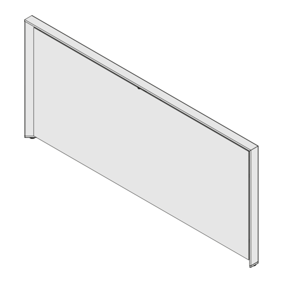
- Page 1 ® Ology FrameOne End Panel ™ ® (with and without Utility Pole) #2 SQUARE 5/32” HEX 5/32” 5/32” 888.STEELCASE (888.783.3522) www.steelcase.com © 2019 Steelcase Inc. Page 1 of 11 Grand Rapids, MI 49501 U.S.A. 1360037001 Rev A...
- Page 2 ® Frame One End Panel with Utility Pole *If no Utility Pole, proceed to Step 2. Single Sided LH Install Extension Box to Mounting Bracket 1a) If assembling frame one end panel with utility pole*, then locate extension box to panel mounting bracket (center on dual sided, left or right for single sided), 1b) install (4) .250-20 x .500 screws (provided) and fasten...
-
Page 3: Assemble Mounting Bracket
® Single Sided Dual Sided Assemble Mounting Bracket 2) Using (3) M6 button head thread forming screws (provided) attach the mounting bracket to underside of cross-tube weldment. TIP: Note hole positions used on single sided (see arrows), centered on dual sided applications. 3a) Use a level to check for vertical orientation. - Page 4 ® See Tip Attach the Frame One End Panel 4a) Position Frame One End Panel against bracket and check for alignment of the pilot holes (6X), 4b) adjust the leveler glides, if necessary, to match the pilot hole pattern to slots in bracket, 4c) secure using (6X) #10-12 x .625 screws (provided).
-
Page 5: Install Trim
® Install Trim TIP: If a utility pole is to be installed and the extension box was not assembled previously, do this now (see Step 1). 5a) Flex sides of trim cover open to overlap mounting bracket, 5b) engage “V-tabs” to slots, then 5c) push cover tight to end panel. - Page 6 ® Install Angle Bracket 7a) Using a level positioned on center of the extension box, 7b) transfer a mark to the top frame tube member, 7c) drill a 5/32" hole in the frame tube at 1" down from your mark, as illustrated.
- Page 7 ® Attach Column 8a) Thread glide into pole base, then 8b) locate into bottom of aluminum column. 9a) Position column with glide base on the floor, and 9b) Adjust glide to align pass through opening and slots to extension box installed in step 1, 9c) install (4) .250- 20 x 1”...
- Page 8 ® Install Utility Pole into Ceiling 10) Remove the ceiling tile where the pole will be placed and raise the utility "C" channel vertical. 11) Cut ceiling tile hole. 12) Assemble ceiling trim plate. 13) Bend retainers up and insert ceiling trim plate into the ceiling tile cut-out.
- Page 9 ® Attach Column 14) Place ceiling tile with trim plate back in ceiling. 15) Remove adjacent ceiling tile. 16) Insert the vertical channel through the ceiling tile hole NOTE: If the vertical channel extends above the ceiling tile more than 4 inches mark and cut excess material off before securing to the frame or junction bracket.
- Page 10 ® Attach Column 18) Attach the ceiling bracket to the top of the vertical channel. 19) Secure crossbar to the ceiling grid. 20) Attach slotted adjustment bracket to the cross bar and fully tighten screw. 21) Attach slotted adjustment bracket to the ceiling bracket.
- Page 11 ® Attach Column 22) Secure junction box to ceiling bracket and complete cabling. 23) Snap the cover in place along the length of the HARDWIRE MODULAR vertical channel. 24) Tighten screws connecting the slotted adjustment bracket to the ceiling bracket as shown on step 21. TO BUILDING TO BEAM 8 - 18 x .375...
Need help?
Do you have a question about the Ology FrameOne and is the answer not in the manual?
Questions and answers