
Related Manuals for Carel heaterSteam UR Series


Summary of Contents for Carel heaterSteam UR Series
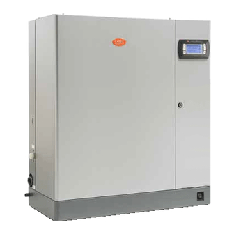
- Page 1 heaterSteam - UR Electric resistance humidifi er User manual NO POWER & SIGNAL CABLES TOGETHER READ CAREFULLY IN THE TEXT! H i g h E f f i c i e n c y S o l u t i o n s...
- Page 3 CAREL Industries, its employees or its branch offi ces/affi liates be responsible for any lack of earnings or sales,...
-
Page 5: Table Of Contents
3. STEAM DISTRIBUTION 11. WIRING DIAGRAMS CAREL jet distributors (SDPOEM00**) ............15 Linear distributors for air pipes (DP***DR0) from CAREL ....15 11.1 Wiring diagram UR002-UR004 single-phase 208 V ......45 CAREL ventilated steam distributors for rooms 11.2 Wiring diagram UR002-UR004 single-phase 230 V ......46 (VSDU0A*, only models UR002...UR013) ............16... -
Page 7: Introduction And Installation
1. INTRODUCTION AND INSTALLATION 1.1 HeaterSteam (UR*) 1.4 Positioning • Range of isothermal resistance humidifi ers, equipped with LED display the unit is designed for wall mounting, suitable to support the weight for the control and distribution of steam. under operating conditions (see par. “Wall mounting”). The models Available models (identifi ed by means of the code on the label, packaging UR020*... -
Page 8: Removing The Front Panel
201 (7.9) Tab. 1.c Fig. 1.f turn the red oval plate with the CAREL logo so that the fastening hole 1.6 Removing the front panel below is visible; slide the panel on the frame (keeping it slightly raised and tilted) until Models UR002…UR013:... -
Page 9: Material Supplied With The Appliance
MADE IN ITALY Equaliser pipe 16 Overtemperature sensors (PTC) Feeding pipe 17 Heaters Water temperature sensor (NTC) CAREL INDUSTRIES Fill-up pipe Via dell'Industria, 11, 35020 Brugine (**) (Padova) Italy Level sensor 19 Thermal insulation cover (**) 10 Overfl ow pipe Fig. -
Page 10: Structure Of Models Ur002 - Ur0013
1.11 Structure of models UR002 – UR0013 Key: Solid state relay (SSR) Safety module (Motor protector, THP) Fuse-holder base (F1, F2) CONTACTOR Transformer Control card Power cable terminal block Pump fuse (F3) Anti-jamming fi lter (where provided) Cable gland for power cables Fan control board Cable gland for auxiliary circuit Cooling fan... -
Page 11: Structure Of Models Ur020 - Ur0080
1.12 Structure of models UR020 – UR0080 Key: Electronic controller Thermal switch (klixon) SSR x 1000 Cooling fan Steam reset Drain Solid state relay (SSR) Fill Alarm Heater fuse (where provided) CONTACTOR Safety module (Motor protector, THP) NTC probe holder Transformer Control card Fuse-holder base (F1, F2, F3) -
Page 12: Hydraulic Connections
2. HYDRAULIC CONNECTIONS Attention:before making the hydraulic connections disconnect the humidifi er from the power supply. Models UR002..UR013 Models UR020...UR080 Fig. 2.a Set up for hydraulic connections: HYDRAULIC CONNECTIONS: install a manual valve upstream (to cut off the water supply); Models UR002..UR013 Models UR020...UR080 connect the humidifi er to the water supply. - Page 13 Hydraulic connections heights: Steam exhaust and condensate drain Drain / Fill Models UR002…UR013 (view from above): Models UR002…UR013 (view from below): Fig. 2.f seize mm (in) Models UR002-UR013 126.7 (5) Fig. 2.d 224 (8.8) 137.9 (5.4) mm (in) 21.7 (0.85) 75 (2.95) 62 (2.44) D’...
-
Page 14: Supply Water
2.1 Supply water The supply water for the electric resistance humidifi er must not be corrosive, must not emit bad odours, and must not contain too much lime to avoid excessive deposits. The water, supplied from mains of drinking water or demineralised water, must have the following characteristics: LIMIT VALUES FOR THE RESISTANCE HUMIDIFIERS WATERS Resistances... -
Page 15: Steam Distribution
3. STEAM DISTRIBUTION 3.1 CAREL jet distributors (SDPOEM00**) They can be mounted either horizontally or vertically (steam exhaust facing upwords). See chapter 12 for distributors models. Mounting instructions (see fi gure): drill a series of holes in the wall of the duct, using the drilling jig of the distributor;... -
Page 16: Carel Ventilated Steam Distributors For Rooms (Vsdu0A*, Only Models Ur002
> 1.2 m (>48”) > 1.2 m (>48”) 3.4 Steam transport pipe • use CAREL fl exible hoses (max 4 m long, see section “Models of steam conducting pipes paragraph 12.2); Fig. 3.e • avoid the formation of pockets or traps (cause of condensate accumulation) •... - Page 17 Models UE020...UR080 (1) extend the pipe inide the humidifi er up to the base tank. Fig. 3.g All the UR models R>300mm R>300mm D> 200mm D> 200mm Fig. 3.h “heaterSteam” +0300075EN - rel. 1.2 - 29.09.2015...
-
Page 18: Electrical Connections
ELECTRICAL CONNECTIONS 4.1 Set up for power cables passageway Models UR002-UR013 loosen the screws and remove the cover (A); if necessary cut the top of the cone cable gland (B) and insert the Models UR002-UR013 power cable; Exterior, view from below Interior, view from above connect the electrical cables to the terminal block, reinsert the cover and fasten it with the screws;... -
Page 19: Control Board
The power line to the humidifi er must be fi tted with a fused disconnect 4.3 Control board protecting against short-circuits, to be mounted by the installer. The The control board (S) is located inside the electrical panel, in the partition table in chapter 12 shows the recommended cross-sections of the power wall. -
Page 20: Steam Production Command Signals
EXTERNAL PROPORTIONAL REGULATOR and REMOTE CONTACT 4.4 Steam production command signals (modulating action) • Attention: follow this sequence of steps in order to avoid connect inputs 7l and 8l to a remote contact (enabling); • damaging the control board: connect outputs 5l and 6l (production command) to an external program the controller and turn it off ;... -
Page 21: Alarm Contact
8 A resistive - 2 A inductive) is made using the removable terminal block H, as per Fig. 4.t. Fig. 4 s shows the connection of the CAREL probe type ASET030001, with measurement range -30T90 °C (Fig.4.s). The CAREL recommended probes Set up for remote indication of the presence of one or more alarms have a 0 to 1V output. -
Page 22: Supervisor Network
5. SUPERVISOR NETWORK 5.1 RS 485 SUPERVISOR NETWORK The control board of the humidifi er can be connected serially RS485 with a remote supervisor system. 24 Vaux Fig. 5.a The transmission line can reach a maximum distance of 1000 metres between the two most distant points. -
Page 23: Commissioning
7. COMMISSIONING Once you have completed the steps in “Preparing for operation”, you can AUTOTEST PROCEDURE start the humidifi er. Indicated by code “At”. See following paragraph. heaterSteam 7.1 Start Steam After closing the main switch of the humidifi er’s power supply, turn the x1000 appliance on by setting the switch located on the front panel, bottom reset... -
Page 24: Shut Down
7.4 Shut down 7.5 User interface • To avoid stagnations, drain the water in the cylinder by simultaneously The front panel contains the display and keyboard, made up from 4 pressing and holding the UP and DOWN keys; keys, which, pressed individually or together, allow to perform all of the •... -
Page 25: Keypad
7.7 Keypad Pressing the button alone: • Press for 5 s: access to the adjusting (P...) and reading (d...) parame- ters reset • reset alarm relay (if the alarm is no longer active) Pressing the button alone: • Displays the unit of measure of the value shown on the display; •... -
Page 26: Setting The Adjusting And Reading Parameters
7.10 Setting the adjusting and reading parameters; The adjustment and reading parameters can be set without password: they include parameters that start with the letter P (adjusting parameters) and with the letter d (measures reading). Procedure: heaterSteam heaterSteam heaterSteam heaterSteam Steam Steam Steam... -
Page 27: Procedures
Steam x1000 confi guration, therefore, the product confi guration should uploaded by reset Drain humiSet, CAREL software for setting the proper confi guration, after Fill recalling the defaults. Alarm Switch the device off ; Press and hold PRG;... - Page 28 7.12.3 Counter reset To reset the counter (parameter d4): heaterSteam Steam x1000 reset Drain Fill Alarm heaterSteam Steam x1000 reset Drain Fill Alarm Press PRG until the display shows P0; Press UP or DOWN until reaching parameter d4; Press the SEL button to display the value of the counter preceded for 1 second by the unit of measure;...
-
Page 29: Configuration Parameters
8. CONFIGURATION PARAMETERS 8.1 Parameter access and setting See chapter 6 “Start and user interface” Note: variable type: A = analog I=full, D = digital. 8.2 Basic operation parameters Variable CAREL Par. Description range notes type protocol 0= ON/OFF command... -
Page 30: Serial Communication Parameters
0 = standard terminal 2= term. with ON/OFF and room probe 1= terminal with ON/OFF command 3= term. with ON/OFF and delivery limit probe Tab. 8.c 8.5 Control parameters Variable CAREL pro- Par. Description range notes type tocol maximum production; in the event of modulation disabled (b0=0), the production is always at 100% of the rated value, 10…100... -
Page 31: Alarms
9. ALARMS 9.1 Alarms table When an alarm is activated a message identifying the alarm is displayed on the control module. In the event of potentially dangerous alarms, the control automatically deactivates the humidifi er (disablement). For some alarm events, an alarm relay is activated simultaneously with the signal (see table). - Page 32 High delivery humidity reprogram- disablement internal memory error contact the CAREL service department ming active humidifi er EEprom CAREL reprogram- with the machine off check that there are no defective or malfunction-...
-
Page 33: Autotest Retry Procedure (Fault Tolerance)
(once having tried the suggestion, if the problem persists action reset alarm relay , contact the CAREL service department) NTC probe for measur- • check the pre-heating operation and the setting of parameters b1, ing the water temper- disablement b2, b3 (see Reading and programming the parameters);... -
Page 34: Troubleshooting
9.3 Troubleshooting Problema Cause Solution 1. check the protection devices upstream of the humidifi er and the mains 1. no electrical power supply; power supply; 2. close the switch on the panel: position I (ON); The control does 2. humidifi er external switch in position 0 (OFF); 3. -
Page 35: Spare Parts And Maintenance
10. SPARE PARTS AND MAINTENANCE Exploded view models UR002- UR013 code no. of kit for single UR N. description UR 2 UR 4 UR 2 / UR 4 "power connection protection URKCR00020 cover (single package)" URKCOPC02S 16 boiler cover kit URKPTCS020 PTC probe (single package) PTC probe wiring... - Page 36 Exploded view models UR002- UR080 code no. of kit for single UR N. description UR 20 UR 27 UR 40 UR20 UR27 UR40 "power connection protective URKCR10020 cover (single package)" URKCOP3020 URKCOP4020 4 boiler cover URKPTCL020 2 PTC probe (single package) PTC probe wiring URKTB00000 terminal board kit...
- Page 37 Other hydraulic parts Important warning: do not use detergents or solvents to clean the plastic components. To remove the deposits use a 20% acetic acid solution, then rinse thoroughly with water. Hydraulic UR 2-13 kg/h code position description UR 2 - 4 UR 6 - 13 fi ll tray kit fi ll tray...
- Page 38 Electric components x 1000 Steam reset Drain Fill Alarm x 1000 Steam reset Drain Fill Alarm Fig. 10.e code UR2-10 UR13 UR13 UR20 UR27 UR40 UR53-60 UR80 N. description “230V “400-460V “208-230V “400-460V “400-460V 460V -575V “400-460V “400-460V 230V 3ph 400 3ph 3ph”...
-
Page 39: Maintenance
10.1 Maintenance Maintenance interventions on the humidifi er should be carried out by specifi cally qualifi ed staff . Important: before proceeding with any operation: • cut off the power supply setting the master switch of the machine to “OFF”; •... - Page 40 loosen the seal strip and remove the steam pipe (1); Fig. 10.h clean the anti-adhesive fi lm that may be present on the inner walls of the boiler (see next section); clean and remove the lime from the boiler and reinsert the fi lm (where needed);...
-
Page 41: Feeding/Drain Tempering Solenoid Valve
Cleaning the heaters After you have removed the limestone that detached more easily, immerse the heaters for 30 minutes in a lukewarm solution of 20% acetic acid, using a non-metallic spatula to remove the surface deposits that are still present. Rinse thoroughly; the plates are coated with anti-adhesive fi lm;... - Page 42 Heaters fuses (humidifi ers UR027 at 230 V, UR060 – UR080 at 460 - 575 V, UR053 – 460 V) Dimension of fast fuses 27x60 housed in fuse carrier bases that can be selected. Check their continuity using a tester. models UR027 UR053...
-
Page 43: Mechanical Discharge Of Water In The Cylinder
Models UR020-UR080 Procedure: • unthread the 2 screws (V), remove the cover (C) and the drain pump; • Check the condition of gasket (G) and replace it, if required. x 1000 Steam reset Drain Fill Alarm Fig. 10.ab Fig. 10.ac Fig. -
Page 44: Electrical Connection Of Boiler Heaters
10.9 Electrical connection of boiler heaters The cable end should be coupled to the top nut applying a torque equal to 3 N · m. Single-phase Single-phase Three-phase - STAR Three-phase - TRIANGLE 2-4 kg/h 208-230 V 6 kg/h 208-230 V 6 kg/h 400 V 6 kg/h 208-230 V 10 kg/h 400-460 V... -
Page 45: Wiring Diagrams
11. WIRING DIAGRAMS 11.1 Wiring diagram UR002-UR004 single-phase 208 V * To be carried out by the installer Terminal Board Motor Protector Fast coupling Contactor Level gauge Sensor terminal block F1 - F2 Primary circuit fuses Drain pump safety fuse Secondary circuit fuse Feed valve Heater temperature sensor... -
Page 46: Wiring Diagram Ur002-Ur004 Single-Phase 230 V
11.2 Wiring diagram UR002-UR004 single-phase 230 V * To be carried out by the installer Terminal Board Motor Protector Fast coupling Contactor Level gauge Sensor terminal block F1 - F2 Primary circuit fuses Drain pump safety fuse Secondary circuit fuse Feed valve Heater temperature sensor Transformer... -
Page 47: Wiring Diagram Ur006 Single-Phase 208 V
11.3 Wiring diagram UR006 single-phase 208 V * To be carried out by the installer Terminal Board Motor Protector Fast coupling Contactor Level gauge Sensor terminal block F1 - F2 Primary circuit fuses Drain pump safety fuse Secondary circuit fuse Feed valve Temperature sensor PTC1…3... -
Page 48: Wiring Diagram Ur006 Single-Phase 230 V
11.4 Wiring diagram UR006 single-phase 230 V * To be carried out by the installer Terminal Board Motor Protector Fast coupling Contactor Level gauge Sensor terminal block F1 - F2 Primary circuit fuses Drain pump safety fuse Secondary circuit fuse Feed valve Temperature sensor PTC1…3... -
Page 49: Wiring Diagram Ur006-Ur010 (208-230-460-575 V) - Ur013 Three-Phase (230-460-575 V)
11.5 Wiring diagram UR006-UR010 (208-230-460-575 V) - UR013 three-phase (230-460-575 V) * To be carried out by the installer Terminal Board Motor Protector Fast coupling CONTACTOR Level gauge Sensor terminal block F1 - F2 Primary circuit fuses Drain pump safety fuse Secondary circuit fuse Feed valve Temperature sensor... -
Page 50: Wiring Diagram Ur006-Ur010-Ur013 Three-Phase (400 V)
11.6 Wiring diagram UR006-UR010-UR013 three-phase (400 V) * To be carried out by the installer Terminal Board Motor Protector Fast coupling CONTACTOR Level gauge Sensor terminal block F1 - F2 Primary circuit fuses Drain pump safety fuse Secondary circuit fuse Feed valve Temperature sensor PTC1…3... -
Page 51: Wiring Diagram Ur020-Ur027 Three-Phase (208-230-460-575 V)
11.7 Wiring diagram UR020-UR027 three-phase (208-230-460-575 V) * To be carried out by the installer Motor Protector Fast coupling CONTACTOR Level gauge Sensor terminal block F1 - F2 Primary circuit fuses Drain pump safety fuse Secondary circuit fuse Feed valve PTC1…3 Temperature sensor heater 1…3 Transformer... -
Page 52: Wiring Diagram Ur020-Ur027 Three-Phase (400 V)
11.8 Wiring diagram UR020-UR027 three-phase (400 V) * To be carried out by the installer Motor Protector Fast coupling CONTACTOR Level gauge Sensor terminal block F1 - F2 Primary circuit fuses Drain pump safety fuse Secondary circuit fuse Feed valve Temperature sensor PTC1…3 heater 1…3... -
Page 53: Wiring Diagram Ur027 Three-Phase (230 V)
11.9 Wiring diagram UR027 three-phase (230 V) * To be carried out by the installer Motor Protector Fast coupling CONTACTOR Level gauge Sensor terminal block F1 - F2 Primary circuit fuses Drain pump safety fuse Secondary circuit fuse Feed valve PTC1…3 Temperature sensor heater 1…3 Transformer... -
Page 54: Wiring Diagram Ur040-Ur053 Three-Phase (460-575 V)
11.10 Wiring diagram UR040-UR053 three-phase (460-575 V) * To be carried out by the installer Motor Protector Fast coupling CONTACTOR Level gauge ST1…2 Sensor terminal blocks F1 - F2 Primary circuit fuses Drain pump safety fuse Secondary circuit fuse Feed valve PTC1…6 Temperature sensor heater 1…6 Transformer... -
Page 55: Wiring Diagram Ur040 - Ur053 Three-Phase (400 V)
11.11 Wiring diagram UR040 - UR053 three-phase (400 V) * To be carried out by the installer Motor Protector Fast coupling CONTACTOR Level gauge ST1…2 Sensor terminal blocks F1 - F2 Primary circuit fuses Drain pump safety fuse Secondary circuit fuse Feed valve PTC1…6 Temperature sensor heater 1…6... -
Page 56: Wiring Diagram Ur053 Three-Phase (460 V)
11.12 Wiring diagram UR053 three-phase (460 V) * To be carried out by the installer Fast coupling CONTACTOR Level gauge ST1…2 Sensor terminal blocks F1 - F2 Primary circuit fuses Drain pump safety fuse Secondary circuit fuse Feed valve PTC1…6 Temperature sensor heater 1…6 Transformer Drain pump... -
Page 57: Wiring Diagram Ur060 Three-Phase (575 V)
11.13 Wiring diagram UR060 three-phase (575 V) * To be carried out by the installer Fast coupling CONTACTOR Level gauge ST1…3 Sensor terminal blocks F1 - F2 Primary circuit fuses Drain pump safety fuse Secondary circuit fuse Feed valve PTC1…9 Temperature sensor heater 1…9 Transformer Drain pump... -
Page 58: Wiring Diagram Ur060 (460-575 V)
11.14 Wiring diagram UR060 (460-575 V) * To be carried out by the installer Fast coupling CONTACTOR Level gauge ST1…3 Sensor terminal blocks F1 - F2 Primary circuit fuses Drain pump safety fuse Secondary circuit fuse Feed valve PTC1…9 Temperature sensor heater 1…6 Transformer Drain pump High level electrodes... -
Page 59: Wiring Diagram Ur060-Ur080 Three-Phase (400 V)
11.15 Wiring diagram UR060-UR080 three-phase (400 V) * To be carried out by the installer CONTACTOR Level gauge ST1…3 Sensor terminal blocks F1 - F2 Primary circuit fuses Drain pump safety fuse Secondary circuit fuse Feed valve PTC1…9 Temperature sensor heater 1…9 Transformer Drain pump High level electrodes... -
Page 60: Wiring Diagram Ur080 Three-Phase (460-575 V)
11.16 Wiring diagram UR080 three-phase (460-575 V) * To be carried out by the installer Fast coupling CONTACTOR Level gauge ST1…3 Sensor terminal blocks F1 - F2 Primary circuit fuses Drain pump safety fuse Secondary circuit fuse Feed valve PTC1…9 Temperature sensor heater 1…6 Transformer Drain pump... -
Page 61: General Features And Models
12. GENERAL FEATURES AND MODELS 12.1 heaterSteam models and electrical features The table below contains the electrical data regarding the power supply voltages of the various models and the functional characteristics of each. Note that some models may be powered at diff erent voltages, obviously with diff erent consumption and steam output. -
Page 62: Technical Features
(4)* (4)* (4)* Tab. 12.d *: use Y-type CAREL kit code UEKY000000, inlet 40mm (1.6”) and 2 outlets 30mm (1.2”) **: use Y-type CAREL kit code UEKY40Y400, inlet 40mm (1.6”) and 2 outlets 40mm (1.6”) “heaterSteam” +0300075EN - rel. 1.2 - 29.09.2015... -
Page 63: Models Of Linear Nozzles And Typical Installations
12.5 Models of linear nozzles and typical installations humidifi er model: UR002 UR004 UR006 UR010 UR013 UR020 UR027 UR040 UR053 UR060 UR080 ø of steam outlet mm (in): 30 (1.2”) 40 (1.6”) 2x40 (1.6”) maximum capacity kg/h (lb/h): (4.4) (8.8) (13.2) (22) (28.6) -
Page 64: Table Of Parameter B1
H > 300 mm H > 500 mm 1/3 H 1/3 H Fig. 12.a 12.6 Table of parameter b1 pre-heating Warning “cl” cumulative alarm relay triggered when… Automatic total drain due to inactivity autotest def. 0 Alarms present Alarms present Alarms absent Alarms present Alarms absent... -
Page 65: Variables Accessible In Serial Mode Only
12.7 Variables accessible in serial mode only Description Type SPV CAREL NOTES St: ambient setpoint Release software Humidifi er status Start Water fi ll-up 1,2,3,4 Autotest Water drain No production AFS drain Steam production in progress Block alarm Block alarms... -
Page 66: Production Control Via Variables A52 And A53
12.8 Production control via variables A52 and A53 Through the network, just after switching on the humidifi er, set the digital variable D15 = 0 (there is no need to repeat this step during operation, unless the humidifi er is turned off ); Set the internal variable I32=3;... -
Page 67: Advanced Functions
13. ADVANCED FUNCTIONS 13.1 Operating principle A0=1 HeaterSteam is an isothermal humidifi er with steam produced by heating the heaters completely immersed in a tank fi lled with water. Steam_Pr This can be tap water or completely demineralised water. The heat generated by the heaters increases water temperature up to about 100 °... -
Page 68: Setting The Alarm Thresholds (Type H Or T Control Module)
Example: if the internally set duration is 10 s and bD= 50%, the new for the type H control module with modulating action and independent duration shall be = 10 s x 50 / 100= 5 s. control. Recommended CAREL transducer: SSTOOB/P40, ASET030001 or Parameter bD ASET030000. Variation range 0 to 190 % (0 % disables the dilution drains. -
Page 69: User-Adjustable Max. Allowed No. Of Evaporation Cycles Between 2 Dilution Drains
13.6 User-adjustable max. allowed no. of 13.8 PWM fi lls after dilution and high-level/ evaporation cycles between 2 dilution foam drains drains After a dilution or high-level/foam drain, water is fi lled into to restore the water level up to the upper ball cock. The number of evaporation cycles between 2 consecutive drains for The fi lled fresh water disturbs the steam production because it decreases dilution is calculated internally, based on the conductivity of the supply... - Page 70 Notes “heaterSteam” +0300075EN - rel. 1.2 - 29.09.2015...
- Page 72 Agenzia: CAREL INDUSTRIES HQs Via dell’Industria, 11 - 35020 Brugine - Padova (Italy) Tel. (+39) 0499 716611 - Fax (+39) 0499 716600 carel@carel.com - www.carel.com...
Need help?
Do you have a question about the heaterSteam UR Series and is the answer not in the manual?
Questions and answers