Table of Contents

Related Manuals for Carel gaSteam UG045


Summary of Contents for Carel gaSteam UG045
-
Page 1: User Manual
- UG Gas humidifier USER MANUAL LEGGI E CONSERVA QUESTE ISTRUZIONI READ AND SAVE THESE INSTRUCTIONS NO POWER & SIGNAL CABLES TOGETHER READ CAREFULLY IN THE TEXT! gaSteam - UG +0300090EN - ENG Up to date version available on www.carel.com... -
Page 3: Important Warnings
The installation of the product must include an earth such operations, which are required/indicated in the user manual, connection, using the special yellow-green terminal available may cause the final product to malfunction; CAREL accepts no in the humidifier. liability in such cases. The customer (manufacturer, developer or... - Page 4 The technical specifications shown in the manual may be changed without prior warning. The liability of CAREL in relation to its products is specified in the CAREL general contract conditions, published on the website www.carel.com and/or by specific agreements with customers;...
-
Page 5: Table Of Contents
Index 4.11 Production request analogue output 4.12 Remote installation of the touch display 4.13 Final checks 1. INTRODUCTION AND INSTALLATION 1.1 gaSteam (UG*) 5. PREPARING FOR OPERATION 1.2 Dimensions and weights 5.1 Preliminary checks 1.3 When opening the packaging 5.2 Different types of gas supply 1.4 Positioning 1.5 Opening 6. - Page 6 12. WIRELESS PROBES 12.1 Installation and electrical connections 12.2 Wireless probe installation 13. ALARM TABLE 14. SPARE PARTS AND MAINTENANCE 14.1 Boiler maintenance 14.2 Cleaning the burner 14.3 Checking ionisation current 14.4 Flue gas temperature sensor 14.5 Water temperature sensor 14.6 Fuses 14.7 Cooling fan 15.
-
Page 7: Introduction And Installation
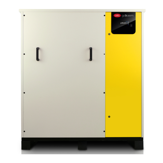
1. Introduction and installation Range of isothermal gas-fired humidifiers for steam production control and distribution, fitted with touch screen graphic display. gaSteam (UG*) Models available (identifiable by the part number shown on the packaging label and on the rating plate): UG045, UG090, UG150, UG180, UG300 and UG450, with steam production capacity up to 450 kg/h (992 lb/h). -
Page 8: Positioning
For installation choose the most suitable position for steam distribution, that is, the position that minimises the length of the steam pipe. The unit has been designed to be floor standing, on a base Positioning that supports its weight in normal operating conditions (see the table of “Dimensions and weights”). The metal casing of the humidifier heats up during operation, and the top part may reach temperatures >... -
Page 9: Material Supplied
1.5.2 Accessing the electrical panel Note: the user terminal (T) is located: on the indoor model: mounted on the door and accessible from the outside; on the outdoor model: inside the unit, in the electrical panel (Q). Indoor model Outdoor model Procedure: Unscrew the screw using a flat-head screwdriver (B) and 1. -
Page 10: Structure
UG45-90-150 UG180-300 UG450 Cable gland Weatherproof cover Flue gas exhaust: straight pipe probe section reducer flange with screws elbow Tab.1.b The figure shows the structure of model UG45; for the other models, see par. “Dimensions by model”. Structure Fig.1.e 10 | 1. Introduction and installation gaSteam - UG +0300090EN rel. -
Page 11: Rating Plate
Ref. Description Ref. Description Disconnect switch 115-230 V transformer (US market) Lock Gas valve Fill solenoid valve Combustion air intake pipe Fill shut-off valve Heater (accessory) Conductivity meter Flue gas exhaust pipe Drain column Safety thermostat Overflow/drain pipe Flame control board Level sensor Ignition electrode Preheating temperature sensor... -
Page 12: Dimensions By Model - Mm(In)
1.9.1 Indoor models Dimensions by model - mm(in) Fig.1.f Ref. Description Ref. Description Flue gas outlet Tank drain Steam outlet Drain column Water inlet Combustion air intake Drain tempering (accessory) Gas inlet Water drain Flame inspection opening Tab.1.d Drain tempering Model No. - Page 13 Fig.1.g Ref. Description Ref. Description Flue gas outlet Tank drain Steam outlet Drain column Water inlet Combustion air intake Drain tempering (accessory) Gas inlet Water drain Flame inspection opening Tab.1.f Drain tempering Model No. burners Flue gas outlets Steam outlets Water inlet Gas inlet Air intake...
- Page 14 1.9.2 Outdoor models Fig.1.h Ref. Description Ref. Description Flue gas outlet Tank drain Steam outlet Drain column Water inlet Combustion air intake Drain tempering (accessory) Gas inlet Water drain Tab.1.g Drain tempering Model No. burners Flue gas outlets Steam outlets Water inlet Gas inlet Air intake...
- Page 15 Fig.1.i Ref. Description Ref. Description Flue gas outlet Tank drain Steam outlet Drain column Water inlet Combustion air intake Drain tempering (accessory) Gas inlet Water drain Tab.1.i Drain tempering Model No. burners Flue gas outlets Steam outlets Water inlet Gas inlet Air intake Tank drain (accessory)
- Page 16 Fig.1.j Ref. Description Ref. Description Flue gas outlet Tank drain Steam outlet Drain column Water inlet Combustion air intake Drain tempering (accessory) Gas inlet Water drain Tab.1.j Drain tempering Model No. burners Flue gas outlets Steam outlets Water inlet Gas inlet Air intake Tank drain (accessory)
-
Page 17: Connections
Pipe connections off valve to allow the appliance to be disconnected during maintenance. We recommend the use of CAREL hoses (P/N FWH3415003), installing a mechanical filter to trap any solid impurities. To make the connection: drain water: use non-conductive plastic tubing resistant up to 100°C (212°F), with an outside diameter of 50 mm (ref. -
Page 18: Drain Water Characteristics
Note that: 1. no relationship can be proven between water hardness and conductivity; nonetheless, as an indication only, water with a hardness of 40°f should have a conductivity of approximately 900-1000 μS/cm at 20 °C. 2. if supplied with water coming from an external reverse osmosis system, an instant flow- rate of 20 l/min (5.28 Gal/min) must be guaranteed. -
Page 19: Air Intake And Flue Connections
For further requirements, use flue gas accessories available on the market. The maximum lengths specified in the following installation diagrams have been verified using CAREL pipes. For the position of the combustion air intake and flue gas outlet, see the paragraph “Dimensions by model”. - Page 20 pipe diameter (aluminium or stainless steel) flue gas exhaust terminal “T” section for condensate collection Expansion in cross-section Tab.2.c pipe diameter (aluminium or stainless steel) UG90 d=80mm d=100mm d=120mm UG180 2 xd = 80mm 2 xd = 100mm 2 xd = 120mm linear section of pipe l= 90°...
- Page 21 Fig.2.c Ref. Description Code Stainless steel flue grille, Ø 80 EXHZ080000 Ø 80 mm extension, L = 1000 EXHP080100 Ø 80 mm extension, L = 500 EXHP080500 Ø 80 mm 90° bend EXHC080080 Stainless steel intake grille, Ø 80 EXHX080000 Internal/external flange, Ø...
-
Page 22: Installation Of The Appliance With Air Intake From The Room
Installation of the gaSteam humidifiers can be also installed as type B appliances, i.e. with air intake from the room where the appliance is installed. appliance with The maximum allowable pressure drop in the ø 80 mm air intake/flue gas exhaust pipes is: air intake from for gaSteam 45/90/180: 0-70 Pa (0-0.70 mbars / 0-0.0101 PSI);... -
Page 23: Pressure Switch
The pressure switch (P/N UGKPRES180, not supplied) is used to verify that there is no return of flue gases in the event of installation with a common flue/chimney. Pressure switch Verity that the water connections are correct, as follows: the feedwater supply line can be closed using a shut-off valve; Checks a mechanical filter is installed on the feedwater line;... -
Page 24: Steam Distribution
3. Steam distribution To achieve optimal humidifier efficiency, the steam produced must be introduced into the room uniformly, in order to prevent the formation of droplets and condensation. This is achieved using linear steam distributors. The right steam distributor must be chosen according to the place where the steam is to be introduced. - Page 25 Increase the distance in the event of: 1. increased air speed in the duct; 2. less turbulence. Mounting instructions (see the figure): drill a series of holes in the wall of the pipe, using the drilling jig of the distributor (found in the packaging of the distributor);...
-
Page 26: High-Efficiency Linear Distributors For Air Ducts Or Ahus
L tot max kg/h lbs/hr DP045D30R0 17.62 DP060D30R0 26.43 DP085D30R0 39.65 DP105D30R0 1048 39.65 DP125D30R0 1245 39.65 DP165D30R0 1640 39.65 DP085D40R0 55.07 DP105D40R0 1015 77.09 DP125D40R0 1222 99.12 DP165D40R0 1636 99.12 DP205D40R0 2025 99.12 DP035D30RH 11.01 DP045D30RH 17.62 DP060D30RH 26.43 DP085D30RH 39.65 DP105D30RH... -
Page 27: Steam Blower For Room Installation
5°. drain pipe CAREL condensate drain pipes: P/N 1312368AXX (ø 10mm) - (CHOSE00516 (5/16”) for the North American market) for DP* series linear steam distributors; P/N 1312353APG (ø 7mm) - (CHOSE0038 (3/8”) for the North American market) for steam blowers and steam nozzles. -
Page 28: Outlet Pressure Limits
Carel steam hoses have a pressure drop of around 150 Pa/m (0.021 psi) (in compliance with the maximum flow- rate recommended by Carel). Carel DP* series linear distributors have a pressure drop of around 25 Pa (0.003psi) (in compliance with the maximum flow-rate recommended by Carel). - Page 29 (0.78”) of water inside the boiler (for all sizes). 3. Steam distribution | 29 gaSteam - UG +0300090EN rel. 1.2 – 09.10.2018...
-
Page 30: Electrical Connections
4. Electrical connections The cables coming from the outside must pass through the side cable glands (see the figure). Wiring requirements Fig.4.a Before making the electrical connections, disconnect the unit from the mains power supply. Check that the unit’s power supply voltage corresponds to the rated value shown inside the electrical Power cable panel. -
Page 31: Power Supply
115 V / 60 Hz to the transformer (connection by Carel) Fig.4.c Note: to avoid unwanted interference, the power cables should be kept separate from the probe signal cables. Important: connect the yellow-green wire to the earth terminal (GND). The humidifier power line must be fitted by the installer with a disconnect switch and protection fuses. -
Page 32: Auxiliary Circuit Transformer
The multi- voltage auxiliary circuit transformer has a primary winding for 230 V (protected by fuses, 10.3x38 mm) and a secondary winding (24 V). The transformer is connected and checked in the factory, Auxiliary circuit according to the rated voltage. transformer The auxiliary connections must be made by running the cables from the outside into the electrical panel compartment through the cable gland located on the side of the humidifier until reaching the plug-in... -
Page 33: Operation And Control
+12 Vdc, maximum current that can be delivered 50 mA; protection M2.3 Probe power supply (+G) against short-circuits Probe power supply (+G) CAREL 0-10 V Digital input for backup/rotation Maximum output current: 5 mA; maximum voltage with open M2.4 function... - Page 34 4.6.1 Operating principle of a gas-fired humidifier In a gas- fired humidifier, the production of steam is obtained inside a boiler containing water that is heated to and then held at boiling temperature. The heat required to boil the water is provided by a heat exchanger, heated by a modulating premixed gas burner.
-
Page 35: Steam Production Control Signals
By setting control based on temperature, the humidifier will continue to produce steam until reaching the desired set point temperature inside the steam bath, and consequently the desired saturation of the air (fog effect). Recommended CAREL transducer: ASET030000 or ASET030001 or NTC probe UEKNTC0*. - Page 36 Fig.4.h Steam production can be started by: HUMIDISTAT (ON/OFF operation): connect terminals 1U and 2U (production request) to a humidistat; short-circuit terminals 7U and 8U (jumper) to enable production; to enable ON/OFF operation, set: Index Parameter Description Ea01 Type of control External ON/OFF signal Ea04 Maximum production...
- Page 37 Index Parameter Description Ea01 Type of control proportional to external signal Set: Hysteresis (0-100%) Ea03 Proportional band Minimum production (25-100%) Maximum production (25-100%) Ec01 Type of main probe Select from: 0-1V, 0-10V, 2-10V, 0-20mA, 4-20mA Tab.4.f Fig.4.k EXTERNAL PROPORTIONAL CONTROLLER and REMOTE CONTACT (modulating operation) connect terminals 1U and 2U (production request) to a humidistat;...
-
Page 38: Control With Humidity Probes
Limit probe type Select from: 0-1V, 0-10V, 2-10V, 0-20mA, 4-20mA Tab.4.h Note: when using Carel 0-10V probes, connect the probe power supply +(G) to terminal “G” on the board rather than terminal 3U. Fig.4.m Note: in industrial environments (IEC EN61000- 6- 2) the signal cables leaving the unit must not exceed 30 m (98’) in length: steam production signal cable (terminals 1U, 2U), digital remote on/off... - Page 39 Type of main probe Select from: 0-1V, 0-10V, 2-10V, 0-20mA, 4-20mA Tab.4.j Note: when using Carel 0-10V probes, connect the probe power supply +(G) to terminal “14” on the terminal block “T” inside the electrical panel, rather than terminal 3U. Fig.4.o CONTROL WITH ONE HUMIDITY PROBE AND LIMIT PROBE short-circuit terminals 7U and 8U (jumper) to enable production;...
- Page 40 The controller will calculate the weighted average between the two probes. The weight of the two probes can also be set. Note: when using Carel 0-10V probes, connect the probe power supply +(G) to terminal “14” on the terminal block “T” inside the electrical panel, rather than terminal 3U.
-
Page 41: Control With Temperature Probes
Fig.4.q The following probes can be connected: CAREL probes for rooms DPWC111000 for air ducts DPDC110000, DPDC210000 for industrial applications DPPC210000 Tab.4.n Note: third-party active probes can also be connected to the controller. The controller also allows autonomous temperature control, and can be connected to a temperature probe TT. - Page 42 Type of main probe Select from: 0-1V, 0-10V, 2-10V, 0-20mA, 4-20mA Tab.4.p Note: when using Carel 0-10V probes, connect the probe power supply +(G) to terminal “14” on the terminal block “T” inside the electrical panel, rather than terminal 3U. Fig.4.s CONTROL WITH ONE TEMPERATURE PROBE AND LIMIT PROBE short-circuit terminals 7U and 8U (jumper) to enable production;...
- Page 43 The controller will calculate the weighted average between the two probes. The weight of the two probes can also be set. Note: when using Carel 0-10V probes, connect the probe power supply +(G) to terminal “14” on the terminal block “T” inside the electrical panel, rather than terminal 3U.
- Page 44 Fig.4.u The following probes can be connected: CAREL probes for rooms DPWC111000 for air ducts DPDC110000, DPDC210000 for industrial applications DPPC210000 Tab.4.t Note: third-party active probes can also be connected to the controller. CONTROL WITH ONE NTC TEMPERATURE PROBE (passive) short-circuit terminals 7U and 8U (jumper) to enable production;...
-
Page 45: Alarm Contact
connect the first NTC probe to terminals 1U and 2U; connect the second NTC probe to terminals 5U and 6U; to enable control, set: Index Parameter Description Ea01 Type of control Modulation with two temperature probes Ea02 Control with two probes Set the weight of the two probes (0-100%) Set: temperature set point (0-100 °C) (32-212°F) -
Page 46: Production Request Analogue Output
4.11 Production The humidifier controller is fitted with an analogue output (0-10 V signal) that reflects the production request. The production request output (0-10 V max 10 mA) is connected to terminals 11U, 12U. request analogue output Fig.4.y Production request analogue output Tab.4.x Important: to avoid unbalanced control, the earth of the probes or external controllers must be connected to the unit controller’s earth. -
Page 47: Preparing For Operation
5. Preparing for operation Before starting the humidifier, check that: the water and electrical connections have been completed and the steam distribution system Preliminary configured according to the instructions contained in this manual; checks the humidifier water shut-off valve is open; the power fuses are installed and intact;... - Page 48 Fig.5.a 5.2.3 Type of calibration Two different types of burner calibration are available: A. Guided; B. Manual. The guided procedure automatically provides the user, step by step, with all the information necessary to complete the calibration process. For the manual procedure, follow the instructions below. 5.2.4 Burner calibration at maximum output Force the burner to operate at maximum output, as shown in the table, by setting the fan to the maximum speed and verifying by flue gas analysis that the CO2 value corresponds to the table.
- Page 49 If the values measured are different: 1. open the front door; 2. remove the gas valve pressure regulator cap and adjust the pressure regulator A (see the figure) using a no. 40 Torx screwdriver: turn clockwise to increase the CO2 value, anticlockwise to decrease it (apply small adjustments, as the adjustment screw is very sensitive);...
-
Page 50: Start-Up And User Interface
6. Start-up and user interface After having connected power using the main disconnect switch (ON), switch the appliance on by moving the switch on the front panel to “ON”. The activation sequence will start, which includes an initial Start-up phase, an autotest phase and finally actual operation. Each step in the activation sequence is identified by a different display. -
Page 51: Shutdown
Whenever the humidifier is started (switch moved from OFF to ON), an autotest procedure is run by default to check operation of the level sensor and the appliance as a whole. The autotest procedure involves a water fill cycle to above the high level (green LED), followed by a drain cycle until below the minimum level (red LED). - Page 52 Position Function home Scheduler settings System date and time Notification centre Alarm list ON/OFF Set point setting System information Descriptive icon of humidifier status Tab.6.a 6.5.1 System menu The System menu provides access to settings that are available without entering a password. Fig.6.c- system menu Menu Description...
- Page 53 Fig.6.e 6.5.3 Notification centre The main messages regarding the activities performed by the humidifier can be quickly displayed in the notification centre. The main screen shows whether any notifications are present, by indicating the number of active notifications. The list of messages that can be viewed in the notification centre is shown below: Type of Message...
- Page 54 Fig.6.g 6.5.5 Set point setting Set the set point, proportional band and maximum production Fig.6.h 6.5.6 System information Menu providing humidifier status, software and hardware information. Fig.6.i Unit status may be as described below: Unit status Description Standby unit in standby and ready to operate Production the unit is producing steam Alarm...
-
Page 55: Complete Programming Tree
Unit status Description Ready for the unit is ready and awaiting to start operation if there is a fault on the main unit. backup test mode for commissioning and to check functions (for example: activate drain pump, activate fill Manual mode valve...) Warning warning notification... - Page 56 Menu D. Inputs/outputs Menu Index Description Level Values read by main probe, limit probe, boiler water temperature, Installer, Analogue inputs feedwater conductivity Service Read status of remote On/Off, motor protector, level sensor float Installer, Digital inputs position, foam sensor Service Installer, Analogue outputs Read current production...
- Page 57 Menu Index Description Level Frost protection Eb11 Set the frost protection function Installer Set the main probe: 0-1V, 0-10V, 2-10V, Main probe Ec01 Installer 0-20mA, 4-20mA, NTC Set the limit probe: 0-1V, 0-10V, 2-10V, 0- Limit/second probe Ec02 Installer 20mA, 4-20mA, NTC Wireless probes Ec03 Set the wireless probes (main/limit)
- Page 58 Menu Index Description Level Unit status with relative production as a Display Master/ Slave system Ed08 %. Press “PRG” to configure the Installer Master/Slave network Display unit operating hours, current production and any alarms Display info on individual unit. Unit 1, Ed09 Installer Unit 2, ...,Unit 20...
- Page 59 Menu Index Description Level Select the port that the supervisor is Regulation from SV Eh07 Installer connected to Information on the type of login Service, i. Logout Logout Ei01 performed. Possibility to logout Installer Tab.6.e 6. Start-up and user interface | 59 gaSteam - UG +0300090EN rel.
-
Page 60: User Menu And Unit Configuration
7. User menu and unit configuration The following paragraphs describe the gaSteam programming menus. The screen index at the top right corresponds to the sequence in each menu in order to reach the specific page. 7.1.1 Clock menu Main menu The Clock menu is used to set the time, date and time zone. -
Page 61: Alarm Thresholds
7.1.3 Alarm thresholds To check that the relative humidity measured by the probe transducer is within certain predefined values, two alarm thresholds can be configured: high relative humidity alarm threshold, for both the main probe and limit probe; low relative humidity alarm threshold for the main probe. On exceeding these thresholds, an alarm is activated and the corresponding relay contact on the main control board is closed. -
Page 62: Menu E. Settings - A. Control
Fig.7.e Symbol Unit of measure °C Degrees Celsius °F Degrees Fahrenheit Tab.7.a Note: if control is by external signal, the humidifier can only be switched ON or OFF. The “Special period” function can be used to set operation (or switch off) for a specific period of time (from day x to day y). - Page 63 Fig.7.h from the system menu, enter the “Settings” menu and enter the password. Then click the “Configuration” icon: Fig.7.i The “Settings” menu also has functions to: set the units of measure; manually drain the water in the boiler. 7.2.1 Control type (Installer menu) Index Parameter Description...
- Page 64 will be calculated between the main probes, depending on the defined weight, and the limit probes will also have their own average, again depending on the defined weight. For “humidity (two probes)“ or “temperature (two probes)” control, only a group of main probes can be defined.
- Page 65 Index Parameter Description Set the set point, differential, min production, max production Default: Set point = 50%rH (42°C) (107.6°F) Ea05 Modulating control Differential = 5%rH (5°C) (9°F) Minimum production = 25% Maximum production = 100% Range: 0-100 7.2.6 Integral function in probe control If using a probe that is connected directly to the humidifier (control: humidity probe), the Integral (I) control function can be selected.
-
Page 66: Menu E. Settings - B. Functions
maintenance operation. The “maintenance alarm” time is the number of boiler operating hours before it needs to be cleaned. During the start- up wizard, the feedwater hardness is entered, and the ”maintenance alarm” depends on this value, as shown in the table below: Water hardness Maintenance alarm Demineralised... - Page 67 production is next needed, the water is thus warmer than ambient temperature and consequently production will start faster. Index Parameter Description Enable preheat Set the water temperature to maintain Set water temperature offset Default: Eb02 Enable preheating Preheating disabled Water temp. set point in the boiler = 70°C (176°F) Offset = 3% rH (3°C/5.4°F) Set point range: 50-80°C (122-194°F) Offset range: 2-20%rH (0-20°C/32-68°F)
- Page 68 Fig.7.k Steam_pr Steam production Pmin Min production Pmax Max production External signal Tab.7.c 7.3.2 Fill cycles in PWM mode after drain to dilute cycles and high level/foam (Installer menu). After a drain to dilute cycle or high level/foam, the fill valve is opened to replenish water up to the maximum level of the float.
- Page 69 Index Parameter Description cycle. Automatic total drain due to inactivity cycle is enabled by default and the maximum inactivity time is three days (72 hours). The boiler will be automatically emptied when gaSteam remains on for at least three days without humidification request. 7.3.4 Periodical drain (Installer menu) If the feedwater is turbid or has a high mineral content, the boiler can be periodically drained in order to clean and dilute the water as much as possible.
- Page 70 M6 (7O, 8O, 9O) = alarm (general) The general alarm (associated, for example, with output M6 - 7O, 8O, 9O) considers all the alarms with shutdown in the list, unless the alarm in question is selected for the other digital output (in this example M5 - 13U, 14U).
-
Page 71: Menu E. Settings - C. Configuration
7.3.9 Frost protection The temperature of the unit is controlled using the burners. When the internal temperature measured is lower than the value of the “Forced preheating threshold” parameter (default value = 10°C (50°F)), the unit switches on the burners to keep the water and therefore the humidifier warm. If the temperature inside the unit is lower than the temperature set for the “Pump drain threshold”... - Page 72 Index Parameter Description Limit probe configuration; Default: Enable: Enabled (depending on the type of control) Type: 0-10V Minimum: 0% rH Maximum: 100% rH Offset: 0 Enable Al (enable alarms): YES Ec02 Limit/second probe Delay: 120 seconds Possible settings: Type: 0-10V/0-1V/NTC/4-20mA/0-20mA/2-10V Minimum: 0-100% rH Maximum: 0-100% rH Offset: 0...
- Page 73 7.4.4 Maximum number of evaporation cycles between drain to dilute cycles settable by the user (Installer menu) The “Evaporation cycles before drain” parameter is used to manually set the maximum number of evaporation cycles allowed between two drain to dilute cycles. The number of evaporation cycles between two successive drain to dilute cycles can also be calculated internally, based on feedwater conductivity.
- Page 74 7.4.6 Set feedwater hardness (Installer menu) To read feedwater hardness, Carel provides an analysis kit (P/N: KITTH00000). The “Water hardness” parameter defines the maintenance alarm for cleaning the boiler and the heat exchanger. Index Parameter Description Set the feedwater hardness...
- Page 75 the first (lower) threshold, a warning is shown without stopping operation; the second (higher) threshold, an alarm is activated and the unit shuts down as a precaution. Index Parameter Description Set the high conductivity thresholds. Default: pre-alert: 1250 μS/cm alarm: 1500 µS/cm Hysteresis: 25 μS/cm Ec16 High conductivity...
-
Page 76: Menu E. Settings – D.master/Slave
Index Parameter Description Set pre-purge speed, minimum speed and maximum speed for rated Ec24 Burner 2 settings steam production Set pre-purge speed, minimum speed and maximum speed for rated Ec25 Burner 3 settings steam production 7.4.12 Burner calibration Also see the chapter “Preparing for operation”. The Burner Calibration submenu is used to access the procedure for configuring and calibrating the burners on the humidifier. -
Page 77: Menu E. Settings - E. Backup
Index Parameter Description Unit 1 Unit 2 Add unit to the Master/Slave system. Ed02 To add a unit to the network enter the unit’s IP address. Scroll between the units using the UP/DOWN buttons Unit 20 Set maximum production of the Master/Slave system. Load: this is the maximum capacity effectively required for the Maximum production Master/Slave system, settable by the user. -
Page 78: Menu E. Settings - F. Manual Mode
After having enabled the backup function, the unit that will start first in the event of simultaneous activation can be selected. Index Parameter Description Define the priority of the units when in backup mode Ee02 Priority when starting Default: Disabled Possible settings: Enabled/Disabled The priority must be set to “YES”... - Page 79 7.8.2 Set the language (Service and Installer menu) The first time that the unit is powered on, the menu language needs to be selected. To change the language, go to screen Eg02. Press “ENTER” and UP/DOWN to set, ESC to exit without changes. Index Parameter Description...
-
Page 80: Menu E. Settings - H. Supervision
7.8.6 Software update from USB pen drive The update package can be downloaded from ksa.carel.com. The unit’s software can be updated using a USB pen drive plugged directly into the c.pHC controller. In the pen drive’s root directory, create an UPGRADE directory and copy the software update file to this directory. - Page 81 Address is the device’s supervision address on the BMS port. Enabling or disabling the parameters “On/Off from SV” and “Control from SV” activates or deactivates the response to the corresponding signals from the supervisor. For other supervisor protocols, select Carel protocol and use the Carel external gateway (supernode for humidification).
- Page 82 “Update?” parameter to “YES”. Important: the controller is not accessible directly on the internet as a firewall guarantees remote access only via a secure connection (Carel tERA cloud or encrypted VPN connection). 7.9.5 Supervisor settings for ModBus or BACnet on TCP/IP (Ethernet port) (Installer menu) Both Modbus and BACnet are available on the Ethernet port;...
-
Page 83: Menu E. Settings - I. Logout
7.10 Menu E. Settings 7.10.1 Logout from the settings menu (Installer and Service menu) - i. Logout To logout, use the icon available in the “Settings” menu Fig.7.n In “character terminal” mode, screen EI01 screen is used to exit the Settings menu and logout. The screen also describes the type of login performed (installer or service). -
Page 84: Master/Slave System
8. Master/Slave system To obtain steam production higher than that provided by one single unit, several humidifiers can be connected together in a Master/Slave system. Description of A maximum of 19 Slave units can be connected to each Master, meaning a total of 20 humidifiers. the system The Master and Slave units are connected using a local Ethernet network, and in the case of just two units (one Master and Slave) involves a direct connection between the two controllers via Ethernet RJ45... -
Page 85: Switch For Connection
The Master/Slave connection of more than two units requires the use of an industrial grade switch. Carel supplies a switch (P/N: KITSE08000) that can connect a maximum of eight units (8 Ethernet ports). If Switch for necessary, use several switches with a cascaded arrangement. -
Page 86: System Configuration
Fig.8.e Systems set up in this way will be able to cover the humidification requirement. In this specific case, the Master will always be the unit with the lowest IP address of those connected to the signal/probes. If necessary, an additional humidifier (backup) can be installed to cover request in the event of malfunctions on one of the units in the system. - Page 87 Procedure: Enter menu Ed07 (E. Settings - d. Network), press PRG and scroll with UP/DOWN until reaching menu Ed03. The “Capacity” parameter identifies the maximum production request for the Master/Slave system, and can therefore be set by the user. The “Maximum capacity” parameter (read-only), on the other hand, indicates the sum of the sizes of each unit added to the system;...
- Page 88 Symbol Unit status Current unit (unit being accessed, display or web server) Online Offline Not configured and not included in the Master/Slave system Tab.8.b The units in the Master/Slave system can also be selected one by one, displaying maximum production, unit status, operating hours, current production request and any alarms.
-
Page 89: Web Server
9. Web server The integrated web server is used to configure and monitor the main unit parameters directly from a PC. In fact, using the Ethernet port on the humidifier controller, the unit can be accessed via a local network Integrated web by simply entering its IP address in the browser. -
Page 90: Web Server Functions
Important: the controller is not accessible directly on the internet as a firewall guarantees remote access only via a secure connection (Carel tERA cloud or encrypted VPN connection). The web server “Home” page provides access to the display, so as to carry out all the configuration operations in the same way as if working directly on the unit. -
Page 91: Unit Hardware Backup
10. Unit hardware backup For applications that require continuous humidity control, a second backup unit may be required, which is automatically activated in the event of a malfunction on the first. The gaSteam controller features a dedicated digital input and output for the backup connection, so as to guarantee, via the normally-open contact, activation of the second unit. -
Page 92: Supervisor Network
11. Supervisor network 11.1 The humidifier can be connected to a supervisor via serial (BMS) or Ethernet network. The Carel, ModBus and BACnet protocols are supported as standard by the units. Protocols and configuration Fig.11.a Port Terminal on c.pHC controller... -
Page 93: Wireless Probes
12.1 For installations where standard wired probes can not be used, (for example, modifications to existing systems), wireless probes can be used. These are connected via a device called an access point (Carel P/N: Installation and WS01AB2M20), for up to four wireless probes. The Carel wireless probes available are for room... -
Page 94: Wireless Probe Installation
Remember to verify the quality of the wireless signal between the access point and each wireless probe. For a complete description of the installation procedure, see the Carel manual on the corresponding probes and access point. To configure the probes, go the screens: Ec03, Ec04, Ec05, Ec06 and Ec07, described in the paragraph “Wireless probes”. -
Page 95: Alarm Table
13. Alarm table Any active alarms will be shown on the corresponding screen with direct access from the display. The Alarm icon starts flashing; pressing the Alarm button once displays the type of alarm. In the event of potentially dangerous alarms, the humidifier automatically stops steam production. For certain alarm events, as well as the alarm signal, the alarm relay is activated (see the Alarm table). - Page 96 Code Alarm Cause Possible solution Reset Action connected Limit probe broken Limit probe or second probe not Stop ALA02 Check probe connection and the type of control selected Manual connected or damaged production connected Preheat. probe NTC water temperature probe not Check preheating operation and the settings of the parameters on Stop ALA03...
- Page 97 Code Alarm Cause Possible solution Reset Action Cannot read lim. probe All the limit wireless probes are not Stop - Stop ALA06 Check probe connections and binding to the access point Wireless working automatic production probe Stop with Check that there is water in the boiler; High boiler The boiler temperature read by the...
- Page 98 Code Alarm Cause Possible solution Reset Action electrical panel and the flame control; check the connections controller malfunction between the unit controller and the intermediate terminal block in the electrical panel Stop with Lev. sensor The level sensor may not be Switch the unit off and clean the boiler, the level sensor and the fill Stop ALC05...
- Page 99 Code Alarm Cause Possible solution Reset Action force pre- preheating activation to protect the the temperature inside the humidifier by fitting additional heaters heating humidifier where necessary. AntiFreeze AntiFreeze in Slave unit. Temperature check the temperature inside and outside of the humidifier. Increase ALA17 Slave force below 10°C, preheating activation to...
-
Page 100: Spare Parts And Maintenance
14. Spare parts and maintenance Before all operations: disconnect the appliance from the mains power supply; close the water supply and gas shut-off valves; drain the water circuit using the manual electric pump function or the drain valve provided, after connecting a pipe to drain the water outside of the unit and avoid flooding. - Page 101 Fig.14.b Fig.14.c Fig.14.d To remove the heat exchanger, proceed as follows: disconnect the cables from the burner electrodes (the detection electrode must be disconnected from the burner control board, see the figure, pos. “A”); remove the fan manifold by undoing the screws B (Fig. 14.c) and remove the burner combustion head (Fig.
-
Page 102: Cleaning The Burner
remove the nuts E from the side of the burner; take out the heat exchanger H and wash it using a 20% acetic acid solution, removing scale using implements that do not scratch the lining (e.g. wood or plastic). At the end of the process, rinse thoroughly. -
Page 103: Checking Ionisation Current
Fig.14.g Fig.14.h 14.3 Ionisation current is checked by placing a microammeter set to 10 µA full scale (direct current) in series with the flame detection electrode. Incorrect positioning of the electrode may lead to a decrease in the Checking ionisation current and burner shutdown due to incorrect flame detection. In this case, check the correct ionisation current position and condition of the electrode, its electrical connections, and the earth connection of the burner. -
Page 104: Fuses
Then replace the sensor by following the same procedure in reverse. Fuses 1, 2, 3 measure 10.3x38 mm and are contained inside the fuse carrier; while fuse 4 measures 6.3x20 14.6 mm; to check the fuses, test continuity using a tester. Use fuses with the ratings indicated in the table: Fuses model UG045, UG090, UG150, UG180, UG300, UG450... -
Page 105: Wiring Diagrams
15. Wiring diagrams 15.1 Electrical panel 300090_153_R01 J17C J17L J6L J6C Fig.15.a 15. Wiring diagrams | 105 gaSteam - UG +0300090EN rel. 1.2 – 09.10.2018... -
Page 106: Wiring Diagram For Ug045 - Ug090 - Ug150
15.2 Wiring diagram for UG045 - UG090 - UG150 300090_150-A_R01 FLAME CONTROL RELAY 1 / RELE' CONTROLLO FIAMMA 1 J22.1 RF1_A1 RELE RF1 INDOOR VERSION / VERSIONE INDOOR RF1_A2 J22.2 NTC SCARICO FUMI 1 Exhaust Fumes 1 NTC OUTDOOR VERSION / VERSIONE OUTDOOR KLIXON MINIMA TEMP. - Page 107 300090_150-B_R01 SENSORI CONDUCIBILITA' conducibility sensor FLAME CONTROL RELAY 2 / RELE' CONTROLLO FIAMMA 2 J22.3 RF2_A1 SENSORI LIV.MAX (SCHIUMA) foam sensor RELE RF2 RF2_A2 J22.2 TACH TO CLIP 5T SHIELD - SCHERMO RELAY BACKUP / ROTATION +12Vdc SONDA AMB. / Control sensor +12V backup EXTERNAL...
-
Page 108: Wiring Diagram For Ug180 - Ug300
15.3 Wiring diagram for UG180 - UG300 300090_151-A_R01 INDOOR VERSION / VERSIONE INDOOR FLAME CONTROL RELAY 1 / RELE' CONTROLLO FIAMMA 1 NTC SCARICO FUMI 2 J22.1 Exhaust Fumes 2 NTC RF1_A1 RELE RF1 NTC SCARICO FUMI 1 RF1_A2 Exhaust Fumes 1 NTC J22.2 OUTDOOR VERSION / VERSIONE OUTDOOR KLIXON MINIMA TEMP. - Page 109 300090_151-B_R01 SENSORI CONDUCIBILITA' conducibility sensor TACH SENSORI LIV.MAX (SCHIUMA) FLAME CONTROL RELAY 2 / RELE' CONTROLLO FIAMMA 2 foam sensor J22.3 RF2_A1 RELE RF2 RF2_A2 J22.2 TACH TO CLIP 5Z - 5T SHIELD - SCHERMO RELAY BACKUP / ROTATION +12Vdc SONDA AMB.
-
Page 110: Wiring Diagram For Ug450
15.4 Wiring diagram for UG450 300090_152-A_R01 FLAME CONTROL RELAY 1 / RELE' CONTROLLO FIAMMA 1 FLAME CONTROL RELAY 2 / RELE' CONTROLLO FIAMMA 2 NTC SCARICO FUMI 1 Exhaust Fumes 1 NTC J22.3 J22.1 RF2_A1 RF1_A1 RELE RF2 RELE RF1 NTC SCARICO FUMI 2 RF2_A2 RF1_A2... - Page 111 300090_152-B_R01 SENSORI CONDUCIBILITA' conducibility sensor TACH SENSORI LIV.MAX (SCHIUMA) foam sensor TACH TO CLIP 5Z - 5T SHIELD - SCHERMO SHIELD - SCHERMO SCHEDA FENWALL 1 Fenwall Controller Board 1 TO GAS VALVE 1 KLIXON 1 SCHEDA FENWALL 2 Fenwall Controller Board 2 TO GAS VALVE 2 KLIXON 2 BRIDGE ON EL.BOARD...
-
Page 112: Electrical Panel
Wiring diagram key Ref. Description Base Selectable fuse carrier cPHC Main board + expansion card Differential pressure switch (180/300/450 kg/h) 3-pin through connector 4-pin through connector Klixon 1/2/3 Safety thermostat TRPS1 115-230 V transformer (UG45-90-150) U-T-S 14-pin through connector 14-pin through connector 4-pin through connector ON/OFF switch (outdoor) Two-pole ON/OFF switch... -
Page 113: General Features And Models
16. General features and models Models for indoor installation: INDOOR models UG045 UG090 UG150 UG180 UG300 rated supply voltage (Vac) 230 V 50 Hz (ver. UG***HD004) / 115V 60 Hz (ver. UG***HD1104) steam connection (Ø mm) 2x40 2x40 1x80 4x40 2x80 steam outlet pressure limits (Pa) 0-2000 (0-0.30 PSI) -
Page 114: Heating-Water Circuit Specifications
type c.pHC auxiliary voltage / frequency (V - Hz) 24 / 50-60 maximum auxiliary power (VA) selectable for signals: 0-1 Vdc, 0-10 Vdc, 2-10 Vdc, 0-20 mA, 4-20 mA probe inputs (general specifications) input impedance: 60 kΩ with signals: 0-1 Vdc, 0-10 Vdc, 2-10 Vdc 50 Ω... -
Page 115: Technical Values Of The Flue Gas According To Useful Heat Input
UG045 UG090 UG150 UG180 UG300 UG450 air intake and flue gas exhaust Tab.16.d * value refers to combustion of natural gas (G20); Tab. 8.b ** m St = dry gas at 15°C and 1013.25 mbar atmospheric pressure; ***: using the specific KITNSTALL for USA. 16.2 Technical values of the flue gas according to useful heat input fuel type natural gas (G20) - Page 116 *: use Carel “Y” kit UEKY000000, inlet 40 mm (1.6”) and 2 outlets x 30 mm (1.2”) **: use Carel “Y” kit UEKY40X400, inlet 40 mm (1.6”) and 2 outlets x 40 mm (1.6”) For the typical installations of linear distributors, see the figure below: Fig.16.a...
- Page 117 Fig.16.b Key: SAKIT80100 SAKIT40200 SAKIT40400 Tab.16.i 16. General features and models | 117 gaSteam - UG +0300090EN rel. 1.2 – 09.10.2018...
- Page 118 118 | gaSteam - UG +0300090EN rel. 1.2 – 09.10.2018...
- Page 120 Delete this text and replace it with your own content. CAREL INDUSTRIES S.p.A. - Headquarters Via dell'Industria, 11 CAREL can accept no responsibility for possible errors in this manual. 35020 Brugine - Padova (Italy) CAREL reserves the right to modify its products without notice Tel.
Need help?
Do you have a question about the gaSteam UG045 and is the answer not in the manual?
Questions and answers