Stahl SolConex 8579/31 Series Operating Instructions Manual
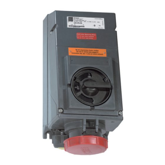
Solconex wall-mounting socket, 63 a
Hide thumbs
Also See for SolConex 8579/31 Series:
- Operating instructions manual (44 pages) ,
- Operating instructions manual (48 pages)
Table of Contents
Advertisement
Available languages
Available languages
Quick Links
Advertisement
Chapters
Table of Contents

Related Manuals for Stahl SolConex 8579/31 Series


Summary of Contents for Stahl SolConex 8579/31 Series
- Page 1 Betriebsanleitung Operating instructions Additional languages www.stahl-ex.com DE EN SolConex Wandsteckdose, 63 A SolConex wall-mounting socket, 63 A Reihe 8579/31 Series 8579/31...
- Page 3 Betriebsanleitung Additional languages www.r-stahl.com SolConex Wandsteckdose, 63 A Reihe 8579/31...
-
Page 4: Table Of Contents
Inhaltsverzeichnis Allgemeine Angaben ...................3 Hersteller ......................3 Angaben zur Betriebsanleitung ................3 Weitere Dokumente ....................3 Konformität zu Normen und Bestimmungen ............3 Erläuterung der Symbole ..................4 Symbole in der Betriebsanleitung ...............4 Warnhinweise .....................4 Symbole am Gerät ....................5 Sicherheitshinweise ....................5 Aufbewahrung der Betriebsanleitung ..............5 Qualifikation des Personals ................5 Sichere Verwendung ...................5 Umbauten und Änderungen ................6... -
Page 5: De De
Die Originalbetriebsanleitung ist die englische Ausgabe. Diese ist rechtsverbindlich in allen juristischen Angelegenheiten. Weitere Dokumente • Datenblatt Steckvorrichtungen SolConeX & CES Dokumente in weiteren Sprachen, siehe www.r-stahl.com. Konformität zu Normen und Bestimmungen Zertifikate und EU-Konformitätserklärung, siehe www.r-stahl.com. Das Gerät verfügt über eine IECEx-Zulassung. Siehe IECEx-Homepage: http://iecex.iec.ch/... -
Page 6: Erläuterung Der Symbole
Erläuterung der Symbole Erläuterung der Symbole Symbole in der Betriebsanleitung Symbol Bedeutung Tipps und Empfehlungen zum Gebrauch des Geräts Gefahr allgemein Gefahr durch explosionsfähige Atmosphäre Gefahr durch spannungsführende Teile Warnhinweise Warnhinweise unbedingt befolgen, um das konstruktive und durch den Betrieb bedingte Risiko zu minimieren. -
Page 7: Symbole Am Gerät
Normen und Bestimmungen umfasst. Für Tätigkeiten in explosionsgefährdeten Bereichen sind weitere Kenntnisse erforderlich! R. STAHL empfiehlt einen Kenntnisstand, der in folgenden Normen beschrieben wird: • IEC/EN 60079-14 (Projektierung, Auswahl und Errichtung elektrischer Anlagen) • IEC/EN 60079-17 (Prüfung und Instandhaltung elektrischer Anlagen) •... -
Page 8: Umbauten Und Änderungen
Funktion und Geräteaufbau Bei Montage und Installation • Montage und Installation nur durch qualifizierte und autorisierte Personen (siehe Abschnitt "Qualifikation des Personals") durchführen lassen. • Gerät nur in Zonen installieren, für die es aufgrund seiner Kennzeichnung geeignet ist. • Bei Installation und im Betrieb die Angaben (Kennwerte und Bemessungsbetriebsbedingungen) auf Typ- und Datenschildern sowie die Hinweisschilder am Gerät beachten. - Page 9 Technische Daten Technische Daten Explosionsschutz Global (IECEx) Gas und Staub IECEx PTB 06.0020 Ex db eb IIC T6 Gb Ex db eb IIC T5 Gb mit eigensicheren Hilfskontakten: Ex db eb ib IIC T6 Gb Ex db eb ib IIC T5 Gb Ex tb IIIC T60°C ...
-
Page 10: Technische Daten
Technische Daten Technische Daten Kurzschlussschutz Hauptkontakte 63 A gG Hilfskontakte 6 A gG Umgebungsbedingungen Umgebungs- T6, T60°C: -30 ... +40 °C temperatur T5, T75°C: -30 ... +55 °C -45 °C auf Anfrage (innere Schmierung mit Silikonfett) Mechanische Daten Anzahl der Pole 3 P + ¿, 3 P + N + ¿... -
Page 11: Transport Und Lagerung
Anschluss- gewinde bei 20 °C M25x1,5 1,5 Nm Weitere technische Daten, siehe www.r-stahl.com. Transport und Lagerung • Gerät nur in Originalverpackung transportieren und lagern. • Gerät trocken (keine Betauung) und erschütterungsfrei lagern. • Gerät nicht stürzen. 201300 / 8579610300 SolConex Wandsteckdose, 63 A 2018-02-28·BA00·III·de·03... -
Page 12: Montage Und Installation
Montage und Installation Montage und Installation Maßangaben / Befestigungsmaße Maßzeichnungen (alle Maße in mm [Zoll]) – Änderungen vorbehalten 04508E00 8579/31 Anordnung der Kontaktbuchse Position: Uhrzeit-Stellung, Ansicht: Vorderseite der Steckdose 02395E00 Anordnung der Kontaktbuchsen und Klemmenbezeichnungen 3 P + ¿ 3 P + N + ¿ 06556E00 06555E00 Anordnung der Kontaktbuchsen und Klemmenbezeichnungen in der 6h-Stellung... - Page 13 Montage und Installation Kennfarbe und Anordnung der Kontaktbuchsen und Klemmenbezeichnungen Polzahl Frequenz Spannung Kennfarbe Lage der [Hz] Schutzkontakt- buchse Alle nicht durch andere Anordnungen hellgrau abgedeckten Nennbetriebsspannungen und/oder Frequenzen 3P + ¿ 50 und 60 100 ... 130 gelb 200 ... 250 blau 380 ...
-
Page 14: 7.2 Montage / Demontage, Gebrauchslage
Montage und Installation Montage / Demontage, Gebrauchslage 7.2.1 Montage Das Gerät ist für den Einsatz im Innen- und Außenbereich geeignet. • Bei Einsatz im Außenbereich Gehäuse und explosionsgeschütztes, elektrisches Betriebsmittel mit Schutzdach oder -wand ausrüsten. Gebrauchslage • Klappdeckel nach unten, Anschlussraum nach oben. - Page 15 • Beigefügtes Schaltbild mit entsprechender Schaltfunktion auf Typschild des Schalters kleben. 12435E00 Demontage Hilfskontakte • Hilfskontakt-Schlüssel (Art.-Nr. 201909) mit dem Stahl-Logo nach oben (!) zwischen Hilfskontakt und Schalterdeckel einführen. • Hilfskontakt zusammen mit Hilfskontakt-Schlüssel heraus- ziehen. 12436E00 Hilfskontakte in Ex i Stromkreisen Werden die Hilfskontakte des Typs 8080/1 in Ex i Stromkreisen eingesetzt, müssen diese...
-
Page 16: Installation
Montage und Installation Die kundenseitige Installation eines eigensicheren Hilfskontakts ist nur dann zulässig, wenn an den beiden Klemmen links und rechts des verwendeten Einbauschachts keine Abgriffklemmen installiert sind! Montage Ex i Abdeckung für Hilfskontakte Die Ex i Abdeckung dient zur Sicherstellung des erforderlichen Fadenmaßes (50 mm) zwischen Anschlussstellen eigensicherer und nicht-eigensicherer Stromkreise. - Page 17 Montage und Installation GEFAHR Explosionsgefahr durch unzureichende Schutzmaßnahmen! Nichtbeachten führt zu schweren oder tödlichen Verletzungen. • Durch geeignete Leiterauswahl sicherstellen, dass maximal zulässige Leitertemperaturen nicht überschritten werden. • Bei Verwendung von Aderendhülsen diese mit geeignetem Werkzeug aufbringen. • Isolationsvermögen und Trennabstände zwischen eigensicheren und nicht-eigensicheren Stromkreisen gemäß...
- Page 18 Montage und Installation Abmessungen [mm] Hauptkontakte Hilfskontakte • Gehäuse öffnen.Leitungen durch Leitungseinführung in Anschlussraum führen.Leitungen abisolieren.Leitungen in entsprechende Klemmen einführen 11201E00 und festklemmen (Anzugsdrehmoment siehe Kapitel "Technische Daten"). Dabei abisolierte Leitungsenden vollständig unter die Klemmplatte stecken.Leitungen auf festen Sitz prüfen.Leitungen ausrichten. Dabei darauf achten, dass Klemmstellen nicht unter Zug stehen.Leitungseinführung(en)
-
Page 19: Inbetriebnahme
Die Wandsteckdose ist nur bei eingestecktem Stecker schaltbar. Bei gezogenem Stecker Klappdeckel mit dem Bajonettring verschließen. Es dürfen ausschließlich Stecker vom Typ 8579/12 der Fa. R. STAHL verwendet werden. Abschließen mit Vorhängeschloss Der Schalter kann mit einem Vorhängeschloss in 0- und I-Stellung abgeschlossen werden. -
Page 20: 10 Instandhaltung, Wartung, Reparatur
Die geltenden nationalen Bestimmungen im Einsatzland beachten. 10.3 Reparatur GEFAHR Explosionsgefahr durch unsachgemäße Reparatur! Nichtbeachten führt zu schweren oder tödlichen Verletzungen. • Reparaturen an den Geräten ausschließlich durch R. STAHL Schaltgeräte GmbH ausführen lassen. SolConex Wandsteckdose, 63 A 201300 / 8579610300 Reihe 8579/31 2018-02-28·BA00·III·de·03... -
Page 21: Reinigung
Reinigung 10.4 Rücksendung Rücksendung bzw. Verpackung der Geräte nur in Absprache mit R. STAHL durchführen! Dazu mit der zuständigen Vertretung von R. STAHL Kontakt aufnehmen. Für die Rücksendung im Reparatur- bzw. Servicefall steht der Kundenservice von R. STAHL zur Verfügung. - Page 22 Operating instructions Additional languages www.r-stahl.com SolConex wall-mounting socket, 63 A Series 8579/31...
- Page 23 Contents General Information ....................3 Manufacturer .......................3 Information regarding the operating instructions ..........3 Further documents ....................3 Conformity with standards and regulations ............3 Explanation of the symbols .................4 Symbols in these operating instructions .............4 Warning notes .....................4 Symbols on the device ..................5 Safety notes ......................5 Operating instructions storage ................5 Personnel qualification ..................5...
-
Page 24: En En
• SolConeX & CES plug and socket devices data sheet For documents in additional languages, see www.r-stahl.com. Conformity with standards and regulations See certificates and EC Declaration of Conformity: www.r-stahl.com. The device has IECEx approval. See IECEx homepage: http://iecex.iec.ch/ Further national certificates can be downloaded via the following link: https://r-stahl.com/en/global/products/support/downloads/. -
Page 25: Explanation Of The Symbols
Explanation of the symbols Explanation of the symbols Symbols in these operating instructions Symbol Meaning Tips and recommendations on the use of the device General danger Danger due to explosive atmosphere Danger due to energised parts Warning notes Warnings must be observed under all circumstances, in order to minimize the risk due to construction and operation. -
Page 26: Symbols On The Device
• Use the device in accordance with its intended and approved purpose only. • Always consult with R. STAHL Schaltgeräte GmbH if using the device under operating conditions which are not covered by the technical data. • Before installation, make sure that the device is not damaged. -
Page 27: Modifications And Alterations
Function and device design For mounting and installation • Have mounting and installation performed only by qualified and authorised persons (see "Personnel qualification" section). • The device is only to be installed in zones for which it is suited based on its marking. •... - Page 28 Technical data Technical data Explosion Protection Global (IECEx) Gas and dust IECEx PTB 06.0020 Ex db eb IIC T6 Gb Ex db eb IIC T5 Gb with intrinsically safe auxiliary contacts: Ex db eb ib IIC T6 Gb Ex db eb ib IIC T5 Gb Ex tb IIIC T60°C to T75°C Db Europe (ATEX) Gas and dust...
-
Page 29: Technical Data
Technical data Technical Data Short-circuit protection Main contacts 63 A gG Auxiliary contacts 6 A gG Ambient conditions Ambient temperature T6, T60°C: -30 to +40 °C T5, T75°C: -30 to +55 °C -45 °C on request (internal lubrication using silicone grease) Mechanical data Number of poles 3 P + ¿, 3 P + N + ¿... -
Page 30: Transport And Storage
20 °C M25x1.5 1.5 Nm For further technical data, see www.r-stahl.com. Transport and storage • Transport and store the device only in the original packaging. • Store the device in a dry place (no condensation) and vibration-free. • Do not drop the device. -
Page 31: Mounting And Installation
Mounting and installation Mounting and installation Dimensions / fastening dimensions Dimensional drawings (all dimensions in mm [inches]) – Subject to modification 04508E00 8579/31 Arrangement of socket contact Position: clock hour position, view: front side of the socket 02395E00 Arrangement of socket contacts and terminal markings 3 P + ¿... - Page 32 Mounting and installation Colour code and arrangement of socket contacts and terminal markings No. of poles Frequency Voltage Colour code Position of earth [Hz] contact sleeve All nominal operating voltages and/or light grey frequencies not covered by other arrangements 3P + ¿ 50 and 60 100 to 130 yellow...
-
Page 33: 7.2 Mounting / Dismounting, Operating Position
Mounting and installation Mounting / dismounting, operating position 7.2.1 Assembly This device is suitable for outdoor and indoor use. • Provide a protective roof or wall if the enclosure and explosion-protected electrical equipment are used outdoors. Operating position • Hinged cover facing downwards, connection chamber facing upwards. - Page 34 Dismounting the auxiliary contacts • Insert the auxiliary contact key (Art. no. 201909) between the auxiliary contact and the switch cover with the Stahl logo pointing upwards (!). • Pull out the auxiliary contact along with the auxiliary contact key.
- Page 35 Mounting and installation Auxiliary contacts in Ex i circuits If the auxiliary contacts of Type 8080/1 are used in Ex i circuits, they must be provided with a covering (Art. No. 168855). The customer is only allowed to install an intrinsically safe auxiliary contact if no pick-off terminal blocks are mounted on the two terminals located on the left and right side of the installation slot used! Mounting Ex i covering for auxiliary contacts...
- Page 36 Mounting and installation DANGER Explosion hazard due to insufficient protective measures! Non-compliance results in severe or fatal injuries. • Select suitable conductors to ensure that the maximum permissible conductor temperatures are not exceeded. • When using core end sleeves, attach them using a suitable tool. •...
- Page 37 Mounting and installation Dimensions [mm] Main contacts Auxiliary contacts • Open the enclosure. Guide the cables through the cable entry into the connection chamber.Strip the cables.Insert the conductors into the corresponding terminals and clamp 11201E00 them (for tightening torque, see chapter "Technical data").
-
Page 38: Commissioning
If the plug has been disconnected, lock the hinged cover with the bayonet ring. Only Type 8579/12 plugs from R. STAHL may be used. Padlocking with a Padlock The switch can be padlocked with a padlock in 0 and I positions. -
Page 39: 10 Maintenance, Overhaul, Repair
DANGER Explosion hazard due to improper repair! Non-compliance results in severe or fatal injuries. • Repair work on the devices must be performed only by R. STAHL Schaltgeräte GmbH. SolConex wall-mounting socket, 63 A 201300 / 8579610300 Series 8579/31 2018-02-28·BA00·III·en·03... -
Page 40: 10.4 Returning The Device
Only return or package the devices after consulting R. STAHL! Contact the responsible representative from R. STAHL. R. STAHL's customer service is available to handle returns if repair or service is required. Contact customer service personally. Go to the www.r-stahl.com website.
Need help?
Do you have a question about the SolConex 8579/31 Series and is the answer not in the manual?
Questions and answers